EP0540077B1 - Anzeigevorrichtung für ein Bildformat mit dem Seitenverhältnis 16/9, die Bilder mit einem Seitenverhältnis 4/3 empfangen kann - Google Patents
Anzeigevorrichtung für ein Bildformat mit dem Seitenverhältnis 16/9, die Bilder mit einem Seitenverhältnis 4/3 empfangen kann Download PDFInfo
- Publication number
- EP0540077B1 EP0540077B1 EP92203096A EP92203096A EP0540077B1 EP 0540077 B1 EP0540077 B1 EP 0540077B1 EP 92203096 A EP92203096 A EP 92203096A EP 92203096 A EP92203096 A EP 92203096A EP 0540077 B1 EP0540077 B1 EP 0540077B1
- Authority
- EP
- European Patent Office
- Prior art keywords
- screen
- line
- circuit
- image
- amplitude
- Prior art date
- Legal status (The legal status is an assumption and is not a legal conclusion. Google has not performed a legal analysis and makes no representation as to the accuracy of the status listed.)
- Expired - Lifetime
Links
Images

Classifications
-
- H—ELECTRICITY
- H04—ELECTRIC COMMUNICATION TECHNIQUE
- H04N—PICTORIAL COMMUNICATION, e.g. TELEVISION
- H04N7/00—Television systems
- H04N7/01—Conversion of standards, e.g. involving analogue television standards or digital television standards processed at pixel level
- H04N7/0117—Conversion of standards, e.g. involving analogue television standards or digital television standards processed at pixel level involving conversion of the spatial resolution of the incoming video signal
- H04N7/0122—Conversion of standards, e.g. involving analogue television standards or digital television standards processed at pixel level involving conversion of the spatial resolution of the incoming video signal the input and the output signals having different aspect ratios
-
- H—ELECTRICITY
- H04—ELECTRIC COMMUNICATION TECHNIQUE
- H04N—PICTORIAL COMMUNICATION, e.g. TELEVISION
- H04N3/00—Scanning details of television systems; Combination thereof with generation of supply voltages
- H04N3/10—Scanning details of television systems; Combination thereof with generation of supply voltages by means not exclusively optical-mechanical
- H04N3/16—Scanning details of television systems; Combination thereof with generation of supply voltages by means not exclusively optical-mechanical by deflecting electron beam in cathode-ray tube, e.g. scanning corrections
- H04N3/22—Circuits for controlling dimensions, shape or centering of picture on screen
- H04N3/223—Controlling dimensions
-
- H—ELECTRICITY
- H04—ELECTRIC COMMUNICATION TECHNIQUE
- H04N—PICTORIAL COMMUNICATION, e.g. TELEVISION
- H04N3/00—Scanning details of television systems; Combination thereof with generation of supply voltages
- H04N3/10—Scanning details of television systems; Combination thereof with generation of supply voltages by means not exclusively optical-mechanical
- H04N3/16—Scanning details of television systems; Combination thereof with generation of supply voltages by means not exclusively optical-mechanical by deflecting electron beam in cathode-ray tube, e.g. scanning corrections
- H04N3/27—Circuits special to multi-standard receivers
Definitions
- the present invention relates to an image display apparatus for displaying images from an input video signal, the apparatus being provided with a display screen in 16: 9 format, and means for display on this screen, comprising a horizontal scanning circuit and a vertical scanning circuit, for displaying on the screen an input image corresponding to the input video signal, the displayed image consisting of a series of lines of DH length, mutually separated from each other vertically by AV spacing, where DH has a DH value and AV has an AV value when a 16: 9 video image is normally displayed on the screen, comprising means analog horizontal adjustment controls, capable of controlling a gradual variation of the scanning amplitude by direct action on said horizontal scanning circuit, and analog means of vertical scanning adjustment, capable of controlling a progressive variation ve of the scanning amplitude by direct action on said vertical scanning circuit.
- patent DE-B-1 121 648 describes an apparatus provided with analog means to modify the vertical amplitude and part of the horizontal amplitude together in order to create a kind of "zoom" effect.
- this device does not solve the above mentioned problem.
- the invention proposes to provide a suitable solution for standard television receivers without image memories or complex image processing means.
- image memories or complex image processing means In addition, it happens, during the televised retransmission of films in "cinemascope" format, that important parts of the image are unused, in particular a band below, and a band above the useful image. It is therefore desirable to be able to enlarge the image.
- an apparatus according to the invention is advantageously provided with means for providing user access to said variation control of said analog adjustment means by a remote control.
- the apparatus is remarkable in that the horizontal scanning circuit with the analog means for adjusting the horizontal scanning consists of a circuit of the type known as the name of the diode modulator, associated with a parabolic generator circuit for a so-called east-west correction, which comprises means for acting on the average DC voltage level of the parabolas in the parabolic generator circuit, for controlling the horizontal amplitude.
- the horizontal scanning circuit with the analog means for adjusting the horizontal scanning consists of a circuit of the type known as the name of the diode modulator, associated with a parabolic generator circuit for a so-called east-west correction, which comprises means for acting on the average DC voltage level of the parabolas in the parabolic generator circuit, for controlling the horizontal amplitude.
- the apparatus further comprising a frame frequency sawtooth generator with an amplifier for injecting said sawtooth current into a beam deflection coil, a feedback being applied to said amplifier, it is advantageously provided with means to vary the amount of this feedback in order to vary the spacing between the lines, and it includes means for clipping the parts of the sawtooth which would produce image points outside the screen.
- the apparatus being provided with a video circuit which delivers a niche of luminance suppression voltage during the line scan returns, it is advantageously provided with means for delivering said niche as soon as video information ceases to be present at the end of a line, and make this slot last at least until video information is again present at the start of the next line.
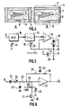
- FIG. 1 shows the screen of a 16/9 ° image display apparatus, suitable for receiving a 4/3 image, in a first situation where the complete reproduction of the image is desired.
- FIG. 2 represents the screen of a 16/9 ° image display device, which receives without transmission a 4/3 format broadcast.
- FIG. 3 represents the screen of a 16/9 ° image display apparatus, suitable for receiving a 4/3 image, in another situation where the greatest possible reproduction of the image is desired.
- Figure 4 shows a special situation in which a film format "Cinemascope” is transmitted according to a standard 4/3, and received on a 16/9 receiver.
- Figure 5 is a diagram of a known vertical scanning circuit to which is added means for adjusting the vertical spacing between the lines and limiting the total vertical amplitude.
- FIG. 6 is a partial diagram of a circuit for generating amplitude control voltages intended for a known diode modulator, diagram to which is added a means of adjusting the line amplitude.
- the following description concerns the case of an image received in 4/3 format on a receiving device provided with a 16/9 e screen .
- the principle of the invention would be difficult to apply to the opposite problem, namely the case of an image received in 16 : 9 format on a receiving device of 4: 3 screen format, because then it would be necessary to increase the 'amplitude lines beyond normal, which we do not know how to do easily.
- One of the merits of the invention is to have noticed that this problem no longer arises in the case of an image received in 4/3 format on a 16/9 e receiver device.
- references 1 and 10 indicate the side edges of the screen of an image receptor in 16 : 9 format.
- References 2 and 20 indicate the lateral edges of an image in 4/3 format, as it should be presented on the screen when it is desired to view it entirely. Part of the screen indicated by hatching is not used.
- FIG. 2 the same image is represented as it would be seen if a 16/9 e receiver were used without special precautions when adjusting its tuner on a PAL or SECAM broadcast with a 4/3 format image.
- the useful life of a PAL or SECAM line and the frame duration are the same as those used for the line and the frame in 16 : 9 format, and the image represented therefore occupies the entire screen.
- references D and F respectively indicate the upper and lower limits of the screen of the image receptor in 16 : 9 format.
- An image received in 4/3 format is presented like this when you want the largest possible image.
- References 3 and 6 indicate the upper and lower limits of image 4/3, which are then outside of the screen. The lateral edges of the image are aligned with those of the screen, but the image parts between limits 3 and D on the one hand and between limits F and 6 on the other hand are lost.
- the situation in FIG. 1 is obtained by recording the image received in such a memory, without displaying it, then by displaying it by re-reading the memory by starting to read. each line in the memory late with respect to the start of the scanning of the line of the screen, so that the reproduced image begins only in 2, and at a speed such that the end of the reading of the line occurs in 20 before the right edge of the screen is reached.
- the situation in FIG. 3 is obtained by starting to read the memory from an address which corresponds to line D of the received image, and by stopping at the line which corresponds to the line F of the received image. Measures may have to be taken to generate additional lines in order to have a number of lines equal to the number of lines on the screen between lines D and F.
- the situation in FIG. 1 is obtained by reducing the amplitude of the horizontal scanning of the cathode ray tube, while the amplitude of the vertical deflection is kept normal.
- the situation in FIG. 3 is obtained by increasing the amplitude of the vertical scanning of the cathode ray tube, that is to say the spacing between the lines, while the amplitude of the horizontal deflection is kept normal.
- DH and AV will be called the horizontal amplitude and the vertical amplitude respectively, and it will be agreed that DH and AV are equal to 1 for normal scanning of the 16 : 9 screen.
- the adjustment means for adjusting the vertical spacing of the lines and the length of the lines of the reproduced image are both dimensioned so as to obtain two values of AV spacing of the lines, namely 1.333 and 1, which are between them in a ratio equal to the ratio between the two aforementioned formats, and two DH values of line length, namely 1 and 0.75, which are between them in the same ratio (1 divided by 0.75 is equal to 1.333).
- the ratio between the formats is 16/9 th divided by 4/3, that is to say a ratio of 4/3 or 1.333.
- the adjustment means are directly accessible by the user of the device, who can therefore choose for himself the situation he wishes.
- the adjustment means are also of a continuously variable type, so that all the intermediate situations between that of FIG. 1 and that of FIG. 3 can also be obtained. Preferably access to such an adjustment is made by means of the device's remote control, which has one or more keys for this purpose.
- FIG. 4 illustrates the advantage of such a possibility:
- FIG. 4A shows the same situation as FIG. 1, in the case where the emission in progress is that of a film in "Cinemascope".
- the right edge of the image received in 4/3 is always indicated by the reference 2, but the top and bottom edges of the useful image, that of the film, indicated by the references 7 and 8, leave a screen portion unused above and below the image.
- a zone 9 is provided for possible subtitles.
- the vertical scanning stage comprises an oscillator 18 synchronized by a synchronization signal brought to an input S, and whose free oscillation frequency is adjusted by a variable resistor 13, followed by a ramp generator 12 which supplies sawtooth signals to an input "+” of an output amplifier 15, which finally supplies a deflection current to a vertical deflection winding 16.
- This winding is connected to the ground via a current measurement resistor 17, and the signal collected at point 18 is brought back to an input "-" of the amplifier 15, to create a feedback, as well as to an input 19 of the ramp generator 12 , via an adjustable resistor 14, in order to create therein an adjustable non-linearity in the shape of an "S" required by the system. All this is known to those skilled in the art.
- a field effect transistor (FET) 11 is mounted with its drain-source space connected in parallel on the resistor 17. This transistor is controlled by a control voltage C applied to its gate.
- the drain-source space of a field effect transistor behaves like an adjustable resistance and this resistance is in parallel on the resistance 17: thus the voltage generated at point 18 by a given current in the deflection winding is variable according to the control voltage C, and consequently the feedback is modified which acts on the amplitude of the deflection current.
- a low power FET transistor model is sufficient, for example that known under the reference "Jedec" BF256.
- the supply voltage of the circuit of Figure 5 can be lowered to the minimum just necessary to allow full vertical scanning of the screen.
- the parts of the vertical scanning sawtooth which would give image points outside the screen for certain adjustments of the gain of the amplifier are clipped, the signal having in this case the form represented in the figure below. resistance 14.
- the apparatus is provided in a manner known per se with a horizontal scanning circuit of the so-called "diode modulator” type.
- a horizontal scanning circuit of the so-called "diode modulator” type.
- Such a circuit is designed to allow a dynamic modification of the horizontal amplitude, that is to say so that this amplitude can vary during the same frame, without influencing the voltages generated from the horizontal scanning circuit. .
- the amplitude can be varied parabolically during the duration of a frame to provide a known correction known as "east-west”.
- Known "diode modulator” circuits are therefore provided with a connection terminal for an amplitude control signal.
- the voltage intended to be applied to this control terminal to thus vary the amplitude is generated by a circuit, an exemplary embodiment of which is shown in FIG. 6.
- a circuit an exemplary embodiment of which is shown in FIG. 6.
- a signal in the form of parabolas generated known is transmitted via a capacitor 21 and three resistors in series 22, 23, 24 to the input of an amplifier 31, the output terminal Po of which is connected to the aforesaid connection terminal for a signal for controlling the amplitude of the diode modulator (not shown).
- Resistance 22 is adjustable in order to adjust the amplitude of the parabolas.
- a capacitor 25 connects the common point of the resistors 22 and 23 to ground.
- a feedback is obtained by means of two resistors 27 and 28 in series between the output of the amplifier (which brings a phase shift of 180 ° to the signal) and its entrance.
- the common point of these two resistors is connected to ground by a capacitor 32 so that the feedback acts only in direct current.
- the amplifier input is also connected to the midpoint of a voltage divider bridge made of two resistors 29 and 33, one of which is variable and which is placed between ground and a "-26V" terminal connected to a voltage source not shown.
- the purpose of the variable resistor 33 is to allow adjustment of the DC voltage level of the amplifier output signal, since it is one of the elements defining the value of the feedback. All this is known to those skilled in the art.
- a field effect transistor (FET) 30 is mounted with its drain-source space connected in parallel on the resistor 33. This transistor plays the role of variable resistor and its gate is controlled by the voltage C.
- the device is equipped with a microprocessor which in particular manages the orders given by the user by means of its remote control unit.
- the control voltage C which is common to the two assemblies of FIGS. 5 and 6, is generated using this microprocessor in response to a command from the remote control.
- This can for example be obtained by programming the microprocessor so that it generates a signal whose form factor varies according to the desired format.
- This signal transmitted via a capacitor, then aligned to ground so as to fix its highest part at zero volts, and finally integrated, thus provides a variable negative DC voltage capable of controlling the gate of the field effect transistors 11 and 30.
- the microprocessor is then also used to manage the amplitude adjustment of the horizontal and vertical scans.
- the adjustment process includes a step in which the microprocessor memorizes the values, which are a little different from one device to another, of the form factor to generate to obtain the two desired limits for the amplitudes. These can thus be adjusted exactly by the microprocessor (at using the memorized values in question). Consequently, the range of adjustment of the above-mentioned adjustment means accessible by the user extends between the two above-mentioned limits.
- the screen scanning is synchronous with the sending of video information by the transmitter, and the line scanning is adjusted. with an amplitude such that the lines shown slightly protrude outside the screen, in particular to make invisible, by pushing it out of the screen, a "sparks" effect at the vertical edges of the image, due to the fact that the receiver seeks to identify video signals when there is no longer any in the received signal.
- the image is displayed as in Figure 1, the vertical edges of the image and the defect are visible.
- the problem does not exist since only the useful points read from the memory are represented.
- a device provided with a video circuit delivering a voltage slot for the suppression of the luminance during the line scan returns, this defect is remedied by the fact that the device is provided with means to start said slot as soon as video information ceases to be present at the end of a line, and to make said slot last for at least until video information is again present at the start of the next line .
- the apparatus comprises a clock circuit with a master clock at a frequency multiple of the line frequency and the color subcarrier frequency, a circuit which provides different synchronization tops by clock time counting, these means can be easily performed by locating the appropriate counting instants of the clock circuit.
- variable format control signal is used to act also on the video amplification circuit, in order to modify the amplitude of the signal applied to the cathode ray tube.
- the video circuits may for example be of the type described in patent application EP-A-0 375 038 of the Applicant, to which reference will be made for more details.
- These video circuits provide, among other things, a preamplification of the video signals with an adjustable gain by means of a variable control voltage, with the aim of modifying the contrast of the image, the television being provided on the other hand with a contrast control circuit comprising a device for comparing the peak values of the video signal with a reference threshold, the signal from exceeding this threshold being applied, after integration, to control the adjustable preamplification gain, and an adjustment device manual of the contrast delivering another control signal, dependent on the user, and which is also applied to control the adjustable gain of preamplification.
- the nominal amplification gain of the video signal being high enough for the peak values of the video signal (of each of the video signals R, G, B,) to reach said reference threshold, for the majority of images received.
- reference is adjustable according to the contrast control from the user, and it is this variation of the threshold which ultimately constitutes the manual contrast adjustment device.
- the correction as a function of the image format is applied so as to modify the reference threshold.
- means for adding, with the desired weighting, the variable format control signal to the user-dependent contrast control signal can easily imagine means for adding, with the desired weighting, the variable format control signal to the user-dependent contrast control signal.
Landscapes
- Engineering & Computer Science (AREA)
- Multimedia (AREA)
- Signal Processing (AREA)
- Computer Graphics (AREA)
- Details Of Television Scanning (AREA)
- Testing, Inspecting, Measuring Of Stereoscopic Televisions And Televisions (AREA)
- Measuring And Recording Apparatus For Diagnosis (AREA)
Claims (6)
- Bildwiedergabeanordnung zur Wiedergabe von Bildern aufgrund eines Eingangsvideosignals, wobei die Anordnung mit einem Wiedergabeschirm im Format 16/9e und mit Mitteln zur Wiedergabe auf diesem Schirm versehen ist, die eine horizontale und eine vertikalen Abtastungsschaltung umfassen, um auf dem Schirm ein Eingangsbild wiederzugeben, das einem Eingangsvideosignal entspricht, wobei das wiedergegebene Bild aus einer Folge von Zeilen mit einer Länge DH gebildet wird, die voneinander vertikal durch einen Abstand AV getrennt sind, wobei DH einen Wert DH und AV einen Wert AV aufweist, wenn ein Videobild im Format 16/9 normal auf dem Schirm wiedergegeben wird, mit analogen Steuerungsmitteln für die horizontale Abtastung, die in der Lage sind, eine fortschreitende Veränderung der Abtastungsamplitude durch direkte Einwirkung auf die genannte horizontale Abtastungsschaltung zu steuern, und mit analogen Mitteln zur Steuerung der vertikalen Abtastung, die in der Lage sind, eine fortschreitende Veränderung der Abtastungsamplitude durch direkte Einwirkung auf die genannte vertikale Abtastungsschaltung zu steuern, dadurch gekennzeichnet, daß sie für den normalen Empfang von Eingangsbildern im Format 4/3 Kommutationsmittel umfaßt, um auf die analogen horizontalen Abtastungssteuerungsmittel so einzuwirken, daß der Amplitude der horizontalen Abtastung der Wert DH = 3/4 DH gegeben wird, ohne die vertikale Abtastung zu beeinflussen, und daß die Variationssteuerung der genannten analogen Mittel für den Benutzer der Anordnung zugänglich ist, wobei diese Mittel so gekoppelt sind, daß sie es dem Benutzer ermöglichen, DH und AV in fortschreitender Weise zu erhöhen und dabei eine Beziehung zwischen DH und AV beibehalten wird, bei der folgendes gilt:

- Anordnung nach Anspruch 1, dadurch gekennzeichnet, daß sie mit Mitteln versehen ist, um den Zugriff des Benutzers auf die genannten Variationssteuerung der genannten analogen Regelmittel über eine Fernsteuerung zu ermöglichen.
- Anordnung nach einem der Ansprüche 1 oder 2, deren Bildschirm eine Kathodenstrahlröhre ist, dadurch gekennzeichnet, daß die horizontale Abtastungssteuerung zusammen mit den analogen Regelmitteln der horizontalen Abtastung aus einer als Diodenmodulator bekannten Schaltung bestehen, die zu einer Parabelerzeugerschaltung für eine sogenannte Ost-West-Korrektur gehört, die Mittel umfaßt, um auf den mittleren Gleichstrom-Spannungspegel der Parabeln in der Parabelerzeugerschaltung zur Steuerung der horizontalen Amplitude einzuwirken.
- Anordnung nach einem der Ansprüche 1 bis 3, deren Bildschirm eine Kathodenstrahlröhre ist und die einen Sägezahn-Teilbildfrequenzerzeuger mit einem Verstärker zur Einspeisung des genannten Sägezahnstroms in eine Strahlablenkspule umfaßt, dadurch gekennzeichnet, daß dem genannten Verstärker eine Rückkopplung zugeführt wird, sie mit Mitteln versehen ist, um die Stärke dieser Rückkopplung zu variieren, um den Abstand zwischen den Zeilen zu variieren.
- Anordnung nach Anspruch 4, dadurch gekennzeichnet, daß sie Mittel umfaßt, um die Impulsspitzen der Sägezahnabschnitte abzuschneiden, die Bildpunkte außerhalb des Schirms erzeugen würden.
- Anordnung nach einem der Ansprüche 1 bis 5, die mit einer Videoschaltung versehen ist, die einen Leuchtdichteunterdrückungs-Austastimpuls während der Zeilenabtastungs-Rückwege versehen ist, dadurch gekennzeichnet, daß sie mit Mitteln versehen, um den genannten Austastimpuls abzugeben, sobald keine Videoinformation mehr am Ende einer Zeile vorhanden ist, und diesen Austastimpuls wenigstens so lange dauern zu lassen, bis wieder eine Videoinformation am Anfang der folgenden Zeile vorhanden ist.
Applications Claiming Priority (4)
| Application Number | Priority Date | Filing Date | Title |
|---|---|---|---|
| FR9112765 | 1991-10-16 | ||
| FR9112765 | 1991-10-16 | ||
| FR9113402 | 1991-10-30 | ||
| FR9113402 | 1991-10-30 |
Publications (2)
| Publication Number | Publication Date |
|---|---|
| EP0540077A1 EP0540077A1 (de) | 1993-05-05 |
| EP0540077B1 true EP0540077B1 (de) | 1997-08-13 |
Family
ID=26229001
Family Applications (1)
| Application Number | Title | Priority Date | Filing Date |
|---|---|---|---|
| EP92203096A Expired - Lifetime EP0540077B1 (de) | 1991-10-16 | 1992-10-08 | Anzeigevorrichtung für ein Bildformat mit dem Seitenverhältnis 16/9, die Bilder mit einem Seitenverhältnis 4/3 empfangen kann |
Country Status (5)
| Country | Link |
|---|---|
| US (1) | US5486870A (de) |
| EP (1) | EP0540077B1 (de) |
| JP (1) | JPH05241523A (de) |
| DE (1) | DE69221580T2 (de) |
| ES (1) | ES2108083T3 (de) |
Cited By (1)
| Publication number | Priority date | Publication date | Assignee | Title |
|---|---|---|---|---|
| CN109491726A (zh) * | 2018-11-16 | 2019-03-19 | 掌阅科技股份有限公司 | 开屏文件的呈现方法、电子设备及计算机存储介质 |
Families Citing this family (15)
| Publication number | Priority date | Publication date | Assignee | Title |
|---|---|---|---|---|
| IT1257909B (it) * | 1992-07-13 | 1996-02-16 | S E I Societa Elettronica Ital | Televisore con commutazione di formato immagine da 16/9 a 4/3. |
| JP3231142B2 (ja) * | 1993-06-18 | 2001-11-19 | 株式会社日立製作所 | 映像圧縮拡大回路及び装置 |
| GB9312690D0 (en) * | 1993-06-18 | 1993-08-04 | Philips Electronics Uk Ltd | Television receiver |
| EP0647065B1 (de) * | 1993-10-02 | 1998-12-02 | Motorola, Inc. | Erzeugung von Vertikalablenksignalen für Fernsehen |
| US5699123A (en) * | 1993-10-20 | 1997-12-16 | Victor Company Of Japan, Ltd. | Television receiver with an adjustable frame size |
| KR0177860B1 (ko) * | 1994-02-04 | 1999-05-01 | 모리시타 요이찌 | 영상신호처리장치 |
| US5600381A (en) * | 1994-06-20 | 1997-02-04 | Thomsom Consumer Electronics, Inc. | Scan velocity modulation circuit |
| KR0144941B1 (ko) * | 1994-09-30 | 1998-07-15 | 김광호 | 와이드 비젼 디스플레이 장치 |
| DE69609264T2 (de) * | 1995-08-09 | 2001-03-15 | Koninklijke Philips Electronics N.V., Eindhoven | Vorrichtung zur Bildanzeige mit Verschiebung des unteren Bildbereichs |
| EP0913993A1 (de) * | 1997-10-28 | 1999-05-06 | Deutsche Thomson-Brandt Gmbh | Verfahren und Vorrichtung zur automatischen Detektion des Formats in einem digitalen Videobild |
| FR2793640B1 (fr) * | 1999-05-14 | 2001-06-08 | Sagem | Moniteur de television a ecran 16/9 |
| US7167216B2 (en) * | 2002-05-03 | 2007-01-23 | Hewlett-Packard Development Company, L.P. | Projection system with adjustable aspect ratio optics |
| EP1408684A1 (de) * | 2002-10-03 | 2004-04-14 | STMicroelectronics S.A. | Videoanzeigeverfahren und -system mit automatischem Abschneiden |
| US20040145595A1 (en) * | 2003-10-21 | 2004-07-29 | Sony Corporation/Sony Electronics Inc. | Method and apparatus for displaying an image on a display with a different aspect ration than the image |
| US20090262263A1 (en) * | 2005-08-31 | 2009-10-22 | Richard Hugh Miller | Multi-standard vertical scan crt system |
Family Cites Families (18)
| Publication number | Priority date | Publication date | Assignee | Title |
|---|---|---|---|---|
| US2510670A (en) * | 1949-02-10 | 1950-06-06 | Garod Radio Corp | Scan magnitude control for cathode-ray tubes |
| DE1121648B (de) * | 1960-02-13 | 1962-01-11 | Blaupunkt Werke Gmbh | Fernsehempfangsgeraet mit einer Einrichtung zur Einstellung der Bildhoehe und der Bildbreite |
| US3970896A (en) * | 1974-11-21 | 1976-07-20 | Redactron Corporation | Vertical deflection circuit |
| US4230974A (en) * | 1979-04-16 | 1980-10-28 | Teletype Corporation | Cathode ray tube deflection circuit having display format selection |
| US4277729A (en) * | 1979-11-19 | 1981-07-07 | Rca Corporation | Simplified vertical deflection circuit |
| GB8304754D0 (en) * | 1983-02-21 | 1983-03-23 | Rca Corp | Variable picture size circuit |
| GB2135859B (en) * | 1983-02-21 | 1986-11-26 | Rca Corp | Picture size control circuit |
| US4763194A (en) * | 1985-08-14 | 1988-08-09 | Rca Licensing Corporation | Selectable raster size for video display |
| DE3722172A1 (de) * | 1987-07-04 | 1989-01-12 | Thomson Brandt Gmbh | Verfahren und vorrichtung zur ausschnittvergroesserung eines fernsehbildes |
| JPH01292984A (ja) * | 1988-05-20 | 1989-11-27 | Sony Corp | 映像信号の方式変換装置 |
| JPH0270174A (ja) * | 1988-09-05 | 1990-03-09 | Nec Corp | 画面サイズ可変式テレビジョン受像機 |
| JP2882584B2 (ja) * | 1988-09-30 | 1999-04-12 | 株式会社東京放送 | 既存テレビジョン放送方法と互換性のあるワイドスクリーンテレビジョン放送方法 |
| FR2640839B1 (fr) * | 1988-12-20 | 1991-03-15 | Portenseigne Radiotechnique | Appareil de reproduction d'image video muni d'un reglage de contraste, et procede de reglage du contraste d'un tel appareil de reproduction |
| US4984081A (en) * | 1989-01-24 | 1991-01-08 | Matsushita Electric Industrial Co., Ltd. | Apparatus for receiving and selecting high-definition television (HDTV) signals and standard television (NTSC) signals |
| DE3939884A1 (de) * | 1989-12-01 | 1991-06-06 | Siemens Ag | Horizontalablenkstufe |
| JP3060475B2 (ja) * | 1990-03-13 | 2000-07-10 | ソニー株式会社 | テレビジョン受像機 |
| US5249049A (en) * | 1990-06-01 | 1993-09-28 | Thomson Consumer Electronics, Inc. | Managing letterbox displays |
| US5043637A (en) * | 1990-12-14 | 1991-08-27 | Thomson Consumer Electronics, Inc. | Transformer coupled voltage clamp for pincushion correction circuit |
-
1992
- 1992-10-08 ES ES92203096T patent/ES2108083T3/es not_active Expired - Lifetime
- 1992-10-08 DE DE69221580T patent/DE69221580T2/de not_active Expired - Lifetime
- 1992-10-08 EP EP92203096A patent/EP0540077B1/de not_active Expired - Lifetime
- 1992-10-09 US US07/958,895 patent/US5486870A/en not_active Expired - Lifetime
- 1992-10-15 JP JP4277311A patent/JPH05241523A/ja active Pending
Cited By (2)
| Publication number | Priority date | Publication date | Assignee | Title |
|---|---|---|---|---|
| CN109491726A (zh) * | 2018-11-16 | 2019-03-19 | 掌阅科技股份有限公司 | 开屏文件的呈现方法、电子设备及计算机存储介质 |
| CN109491726B (zh) * | 2018-11-16 | 2021-11-09 | 掌阅科技股份有限公司 | 开屏文件的呈现方法、电子设备及计算机存储介质 |
Also Published As
| Publication number | Publication date |
|---|---|
| DE69221580D1 (de) | 1997-09-18 |
| DE69221580T2 (de) | 1998-02-19 |
| JPH05241523A (ja) | 1993-09-21 |
| US5486870A (en) | 1996-01-23 |
| EP0540077A1 (de) | 1993-05-05 |
| ES2108083T3 (es) | 1997-12-16 |
Similar Documents
| Publication | Publication Date | Title |
|---|---|---|
| EP0540077A1 (de) | Anzeigevorrichtung für ein Bildformat mit dem Seitenverhältnis 16/9, die Bilder mit einem Seitenverhältnis 4/3 empfangen kann | |
| EP0194944B1 (de) | Konvergenzvorrichtung für Videoprojektionssystem | |
| FR2596604A1 (fr) | Appareil de reglage automatique du gain dans le canal du son d'un systeme de traitement d'un signal video brouille | |
| FR2482815A1 (fr) | Dispositif de codage et de decodage de signaux d'image et de son | |
| FR2505116A1 (fr) | Generateur de bords a commutation de video, permettant d'augmenter la dimension d'une bordure complete, ou d'ombre projetee sur deux bords et/ou d'un contour associes | |
| FR2617356A1 (fr) | Visiophone | |
| FR2482813A1 (fr) | Dispositif de codage et de signaux d'image et de son | |
| JPH05316446A (ja) | 階調補正装置 | |
| WO1994021080A1 (fr) | Dispositif d'affichage de caracteres dans un systeme video | |
| FR2551287A1 (fr) | Agencement de television a balayage progressif interpole | |
| FR2538656A1 (fr) | Procede et circuit d'asservissement en frequence et en phase d'un oscillateur local en television | |
| EP0375038B1 (de) | Videobildwiedergabevorrichtung mit einer Kontrastregeleinheit und Verfahren zur Kontrasteinstellung einer solchen Wiedergabevorrichtung | |
| FR2684510A1 (fr) | Appareil d'affichage a balayage. | |
| US20020140865A1 (en) | Method of correcting color saturation of video signals | |
| FR2473240A1 (fr) | Camera couleur comportant un circuit de correction d'ouverture verticale | |
| FR2530395A1 (fr) | Etage d'attaque a gain pouvant etre preetabli a la main pour un tube-image dans un systeme de reglage automatique de la polarisation du tube-image | |
| FR2593658A1 (fr) | Recepteur de television repondant a plusieurs signaux video. | |
| FR2625399A1 (fr) | Dispositif de regulation de debit conjointe a au moins deux composantes de signaux video numeriques | |
| FR2494943A1 (fr) | Circuit d'effacement video avec allure controlee de deseffacement | |
| FR2545307A1 (fr) | Appareil de projection d'images videos en couleurs sur un ecran de grandes dimensions | |
| FR2530908A1 (fr) | Circuit d'amelioration du rapport signal/bruit pour un signal video en couleurs | |
| FR2507420A1 (fr) | Dispositif de reproduction de television en couleur comportant une pluralite de tubes-images | |
| EP0649248B1 (de) | Bildanzeigevorrichtung mit Modulation der Lichtpunktgeschwindigkeit | |
| JPH04286492A (ja) | テレビジョン受像機 | |
| EP0064898B1 (de) | Steuerschaltung für Fernsehablenkung |
Legal Events
| Date | Code | Title | Description |
|---|---|---|---|
| PUAI | Public reference made under article 153(3) epc to a published international application that has entered the european phase |
Free format text: ORIGINAL CODE: 0009012 |
|
| AK | Designated contracting states |
Kind code of ref document: A1 Designated state(s): DE ES FR GB IT |
|
| 17P | Request for examination filed |
Effective date: 19931026 |
|
| 17Q | First examination report despatched |
Effective date: 19950830 |
|
| GRAG | Despatch of communication of intention to grant |
Free format text: ORIGINAL CODE: EPIDOS AGRA |
|
| GRAH | Despatch of communication of intention to grant a patent |
Free format text: ORIGINAL CODE: EPIDOS IGRA |
|
| GRAH | Despatch of communication of intention to grant a patent |
Free format text: ORIGINAL CODE: EPIDOS IGRA |
|
| GRAA | (expected) grant |
Free format text: ORIGINAL CODE: 0009210 |
|
| RAP1 | Party data changed (applicant data changed or rights of an application transferred) |
Owner name: PHILIPS ELECTRONIQUE GRAND PUBLIC Owner name: PHILIPS ELECTRONICS N.V. |
|
| AK | Designated contracting states |
Kind code of ref document: B1 Designated state(s): DE ES FR GB IT |
|
| REF | Corresponds to: |
Ref document number: 69221580 Country of ref document: DE Date of ref document: 19970918 |
|
| ITF | It: translation for a ep patent filed | ||
| GBT | Gb: translation of ep patent filed (gb section 77(6)(a)/1977) |
Effective date: 19971016 |
|
| REG | Reference to a national code |
Ref country code: ES Ref legal event code: FG2A Ref document number: 2108083 Country of ref document: ES Kind code of ref document: T3 |
|
| PLBE | No opposition filed within time limit |
Free format text: ORIGINAL CODE: 0009261 |
|
| 26N | No opposition filed | ||
| REG | Reference to a national code |
Ref country code: ES Ref legal event code: PC2A |
|
| REG | Reference to a national code |
Ref country code: FR Ref legal event code: TP |
|
| REG | Reference to a national code |
Ref country code: GB Ref legal event code: IF02 |
|
| PGFP | Annual fee paid to national office [announced via postgrant information from national office to epo] |
Ref country code: GB Payment date: 20101029 Year of fee payment: 19 Ref country code: IT Payment date: 20101025 Year of fee payment: 19 |
|
| PGFP | Annual fee paid to national office [announced via postgrant information from national office to epo] |
Ref country code: ES Payment date: 20111130 Year of fee payment: 20 Ref country code: FR Payment date: 20111115 Year of fee payment: 20 |
|
| PGFP | Annual fee paid to national office [announced via postgrant information from national office to epo] |
Ref country code: DE Payment date: 20120102 Year of fee payment: 20 |
|
| REG | Reference to a national code |
Ref country code: GB Ref legal event code: 732E Free format text: REGISTERED BETWEEN 20120906 AND 20120912 |
|
| REG | Reference to a national code |
Ref country code: DE Ref legal event code: R071 Ref document number: 69221580 Country of ref document: DE |
|
| REG | Reference to a national code |
Ref country code: DE Ref legal event code: R071 Ref document number: 69221580 Country of ref document: DE |
|
| REG | Reference to a national code |
Ref country code: GB Ref legal event code: PE20 Expiry date: 20121007 |
|
| REG | Reference to a national code |
Ref country code: ES Ref legal event code: PC2A Owner name: TP VISION HOLDING B.V. Effective date: 20121030 |
|
| REG | Reference to a national code |
Ref country code: DE Ref legal event code: R082 Ref document number: 69221580 Country of ref document: DE Representative=s name: PODDIG, DIETER, DIPL.-ING., DE |
|
| PG25 | Lapsed in a contracting state [announced via postgrant information from national office to epo] |
Ref country code: GB Free format text: LAPSE BECAUSE OF EXPIRATION OF PROTECTION Effective date: 20121007 |
|
| REG | Reference to a national code |
Ref country code: DE Ref legal event code: R082 Ref document number: 69221580 Country of ref document: DE Representative=s name: PODDIG, DIETER, DIPL.-ING., DE Effective date: 20130130 Ref country code: DE Ref legal event code: R081 Ref document number: 69221580 Country of ref document: DE Owner name: TP VISION HOLDING B.V., NL Free format text: FORMER OWNER: KONINKLIJKE PHILIPS ELECTRONICS N.V., EINDHOVEN, NL Effective date: 20130130 |
|
| REG | Reference to a national code |
Ref country code: ES Ref legal event code: FD2A Effective date: 20130702 |
|
| PG25 | Lapsed in a contracting state [announced via postgrant information from national office to epo] |
Ref country code: ES Free format text: LAPSE BECAUSE OF EXPIRATION OF PROTECTION Effective date: 20121009 |