EP0540173A2 - Séparation de couleurs pour impression graphique à jet d'encre - Google Patents
Séparation de couleurs pour impression graphique à jet d'encre Download PDFInfo
- Publication number
- EP0540173A2 EP0540173A2 EP92308860A EP92308860A EP0540173A2 EP 0540173 A2 EP0540173 A2 EP 0540173A2 EP 92308860 A EP92308860 A EP 92308860A EP 92308860 A EP92308860 A EP 92308860A EP 0540173 A2 EP0540173 A2 EP 0540173A2
- Authority
- EP
- European Patent Office
- Prior art keywords
- black
- color
- byte
- block
- bit
- Prior art date
- Legal status (The legal status is an assumption and is not a legal conclusion. Google has not performed a legal analysis and makes no representation as to the accuracy of the status listed.)
- Granted
Links
Images


Classifications
-
- H—ELECTRICITY
- H04—ELECTRIC COMMUNICATION TECHNIQUE
- H04N—PICTORIAL COMMUNICATION, e.g. TELEVISION
- H04N1/00—Scanning, transmission or reproduction of documents or the like, e.g. facsimile transmission; Details thereof
- H04N1/46—Colour picture communication systems
- H04N1/52—Circuits or arrangements for halftone screening
-
- G—PHYSICS
- G06—COMPUTING OR CALCULATING; COUNTING
- G06K—GRAPHICAL DATA READING; PRESENTATION OF DATA; RECORD CARRIERS; HANDLING RECORD CARRIERS
- G06K15/00—Arrangements for producing a permanent visual presentation of the output data, e.g. computer output printers
- G06K15/02—Arrangements for producing a permanent visual presentation of the output data, e.g. computer output printers using printers
- G06K15/10—Arrangements for producing a permanent visual presentation of the output data, e.g. computer output printers using printers by matrix printers
- G06K15/102—Arrangements for producing a permanent visual presentation of the output data, e.g. computer output printers using printers by matrix printers using ink jet print heads
-
- G—PHYSICS
- G06—COMPUTING OR CALCULATING; COUNTING
- G06K—GRAPHICAL DATA READING; PRESENTATION OF DATA; RECORD CARRIERS; HANDLING RECORD CARRIERS
- G06K2215/00—Arrangements for producing a permanent visual presentation of the output data
- G06K2215/0002—Handling the output data
- G06K2215/0062—Handling the output data combining generic and host data, e.g. filling a raster
- G06K2215/0071—Post-treatment of the composed image, e.g. compression, rotation
-
- G—PHYSICS
- G06—COMPUTING OR CALCULATING; COUNTING
- G06K—GRAPHICAL DATA READING; PRESENTATION OF DATA; RECORD CARRIERS; HANDLING RECORD CARRIERS
- G06K2215/00—Arrangements for producing a permanent visual presentation of the output data
- G06K2215/0082—Architecture adapted for a particular function
- G06K2215/0094—Colour printing
Definitions
- This invention relates to the field of liquid ink printing systems, for example ink jet printing systems, and, more particularly, to methods for improving resolution and print quality in four-color ink jet printing systems.
- CMY Cyan, Magenta and Yellow
- Process black composite black
- Some ink jet printers employ both a color pen and a black pen, but not for use at the same time. In other words, only one or the other pen may be used in the printer at one time.
- Commercial examples are the Hewlett-Packard DeskWriter CTM and DeskJet 500 CTM. Because only one pen can be used at a time, a page is either color or black, but not a mix of color and black on the same page. The user must manually swap pens before a page prints if the wrong pen is in the printer. When the color pen is in use, areas that should be black are printed using composite black. This compromises print quality and printing speed, for the reasons stated above.
- CMYK primary colors plus black
- CMYK complementary metal-oxide-semiconductor
- CMYK complementary metal-oxide-semiconductor
- the Hewlett-Packard PaintJet XLTM contains four print heads, one each for CMY and K. While that printer does not have to use composite black, its resolution is only 180 dots per inch (DPI).
- the Kodak DOCONIX Color 4 Printer also contains four print heads for CMYK, only at 192 DPI.
- the Sharp JX-730 Color Ink Jet Printer is another four color printer that is 216 DPI. Both the Kodak and Sharp printers can print black adjacent to color, but again, at much lower resolution and only on special paper.
- An object of the present invention is to allow mixing color and true black printing within a single printed page at high resolution.
- Another object is to increase resolution in four-color liquid ink printing on plain non-glossy paper.
- Yet another object is to maximize use of true black ink rather than composite black ink in a four-color (CMYK) printing system, while maintaining a predetermined minimum spacing between true black ink and color ink to preserve print quality.
- CYK four-color
- a further object is to compensate for pen misalignment in a two-pen four-color printing system.
- Another object is to speed processing of bit-map color plane data to improve printing speed in a color printing system.
- Another object is to design and implement a very high speed strategy for modifying bit-map color plane data so as to maximize use of true black ink while maintaining a minimum spacing between black ink and color ink, all without unduly slowing the printing process.
- Yet another object of the invention is to allow users to mix color and black on the same printed page. For example, to allow users to print a business letter with a color bar-chart in the middle of a page of text.
- the black will be from the black pen; the colors from the color pen.
- the method initially separates data that represents black from data that represents color.
- Data that represents black is moved into a "K plane" from the CMY planes.
- the CMY planes control their respective colors in the color pen, and the K plane controls the K pen.
- the present method calls for first identifying color graphics data in the color (CMY) planes that represents process black (i.e. the corresponding bits are turned on in all three CMY planes); and replacing that data with data in the K plane. This is done in a manner that maintains a predetermined minimum spacing - delta - between K plane bits and color plane bits. Initially, composite black data is moved from the CMY planes to the K plane, thus changing it from representing composite black to representing (true) black. But this cannot be done blindly, as the new K plane data in some cases would violate the minimum spacing restriction. In such cases, composite black must be used. So the method next detects and corrects minimum spacing violations.
- the next step is to recheck the data to detect new spacing violations resulting from the corrections, etc.
- This re-checking may be implemented recursively, though it need not necessarily be done in that manner. Additional details for carrying out these methods at high speed, to maximize printing throughput, are disclosed.
- the challenge in performing the needed color separation is to overcome the overwhelming number of bits in the bit planes that must be examined.
- CMY planes which are approximately 1 Megabyte each
- black tables which are 16 Kilobytes each
- the method proceeds with examining the true black data and the color data, to detect data representing black dots within a predetermined minimum spacing from color dots. If such data is detected, it is corrected by re-designating the offending black data as composite black data for printing in color ink. This new color data may be too close to black data, however. So the method further calls for repeating the examining and re-designating steps until no black dots are detected within the predetermined minimum spacing from color dots.
- printing the data includes printing the true black data using black ink, and printing the color data, including the composite black bits, using color ink, thereby maintaining at least the minimum spacing between black dots and color dots on the printed page.
- the step of examining the data is done expeditiously by first selecting a block size equal to at least the minimum spacing in both vertical and horizontal dimensions. Next is partitioning the input data to define a series of blocks of the selected block size. Each one of the series of blocks is designated as one of color, black or white. Having done so, we examine the block designations to detect black blocks adjacent color blocks. Where this occurs, the detected black blocks are re-designated as color blocks. These steps are repeated until no black blocks are detected adjacent color blocks, thereby ensuring at least the minimum spacing between color data and black data. Thereafter, printing the black blocks using black ink and printing the color blocks using color inks completes the printing process.
- the processed data can of course be stored to a file or otherwise transferred, for example, for deferred or remote printing operations.
- each block has a series of bits, each black table bit corresponding to a respective one of the K plane blocks, and indicating by its binary state whether or not the corresponding K plane block is a black block.
- the color table has a series of bits, each color table bit corresponding to a respective one of the color plane blocks and indicating whether or not the corresponding color plane block is a color block.
- the method calls for examining adjacent bits in the black table as follows. First, testing a corresponding black table byte to detect an indication of a black block to the left or right of the color table bit, thereby indirectly detecting a black block adjacent the color block. The method further includes testing black table bytes directly above and below the corresponding black table byte detect any adjacent on bits indicating adjacent black blocks. Diagonally adjacent locations in the black table are tested as well.
- the invention thus includes methods of processing the graphics input data for output at high resolution with adequate color separation.
- the resulting output data may be used to drive a CRT or other color display device, or to control a liquid-ink printer as is illustrated in the preferred embodiment.
- the new methodology is useful in any output or rendering application in which separation of one "color" (black in the example) from other colors by at least a minimum spacing is desired.
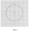
- FIG. 1 is an illustration of an array of ink dot locations on a substrate.
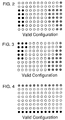
- FIGS. 2-4 illustrate examples of valid configurations of ink drops applied to a substrate in which a predetermined minimum distance (delta) is maintained between each black dot and each color or composite black dot.
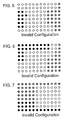
- FIGS. 5-7 illustrate examples of invalid configurations of ink dots applied to a substrate in that, in each example, at least one color or composite black dot is located less than the minimum spacing from a black dot.
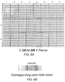
- FIG. 8A illustrates a portion of a combined color plane which is partitioned to form three rows by eight columns of blocks, each block consisting of eight bytes of data.
- FIG. 8B illustrates a portion of a color table in which each bit corresponds to a respective one of the data blocks of FIG. 8A and indicates whether or not the corresponding block has any color bits ON.
- FIG. 9A illustrates a K (black) plane which is partitioned to form three rows by eight columns of blocks in the same manner as the color plane of FIG. 8A.
- FIG. 9B illustrates a portion of a black table in which each bit corresponds to a respective one of the data blocks of FIG. 9A and indicates whether or not the corresponding block has any K bits ON.
- FIG. 10 is a conceptual diagram illustrating a method according to the present invention of processing CMY color data for printing by a 4-color (CMYK) liquid ink printing system so as to maximize use of black ink while maintaining a predetermined minimum spacing between black blocks and color blocks.
- CMYK 4-color
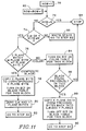
- FIG. 11 is a flowchart of a process for determining whether a given block of data is color, white or black, ie. whether a given block should be printed by the color pen or the black pen.
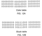
- FIG. 12 illustrates a portion of a color table in which one bit is ON, and identifies the pertinent surrounding bits in the corresponding black table.
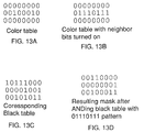
- FIG. 13A is a portion of a color table with two bits ON.
- FIG. 13B is the color table of FIG. 13A with neighbor bits turned ON.
- FIG. 13C is a portion of a black table corresponding to FIGS. 13A and 13B.
- FIG. 13D shows the resulting mask after logically ANDing the black table of FIG. 13C with the mask of FIG. 13B.
- FIG. 14A shows a portion of a color table in which the leftmost bit of one byte is ON.
- FIG. 14B is a portion of a black table corresponding to the color table of FIG. 14A and indicating by 1's the bit adjacent the ON bit of FIG. 14A.
- FIG. 14C is a portion of a color table in which the rightmost bit of a selected byte is ON.
- FIG. 14D is a portion of a black table corresponding to the color table of FIG. 14C and indicating by 1's the bits adjacent the ON bit of FIG. 14C.
- FIGS. 15-17 show a flowchart of a method of examining the color table and black table to detect black blocks which are adjacent to color blocks.
- FIG. 18 is a flowchart of a method of moving selected data into the color planes from the black plane in order to correct minimum spacing violations.
- FIGS. 19-21 illustrate operation of the invention as applied to a specific example of a graphics image.
- CMY The colors Cyan, Magenta and Yellow are referred to as CMY .
- Black is referred to as K (K instead of B, so as to not confuse this color with Blue).
- two pens are provided - one containing the color inks CMY and the other containing black ink. These are called the color pen and the black pen, respectively.
- Black printed on the page using the color pen i.e. a combination of CMY
- black printed on the page using the black pen will simply be called black.
- a dot (also called a pixel) is the smallest single area on the page that a pen can place ink.
- a commercial embodiment of the invention provides for printing at a resolution of 300 Dots Per Inch (DPI) both vertically and horizontally.
- DPI Dots Per Inch
- the input data to a printing system indicates where to place ink on the printed page in the form of bit-map planes.
- a plane conceptually is a two-dimensional array of bits corresponding to a particular a page to be printed. Each plane contains the data for one color. There may be three color planes, for example CMY, as noted above. Any desired color may be obtained by combinations of these colors. Other systems may use RGB (red-green-blue) color planes, as is common in video display systems.
- Each bit in a plane represents one dot location on the page. If the bit is on (value 1), the ink for that color plane for that dot is printed. If the bit is off (value 0) nothing is printed for that color plane for that dot. Since all three color planes are frequently considered together in this specification, we shall refer to "a bit in the color planes" to mean the corresponding bits (i.e. those having the same row/col location) in all three color planes. Similarly, we will refer to a "block of data in the color planes" to mean the corresponding blocks of data in all three color planes. In some systems, input data may comprise four planes, one each for the colors CMY and one for black (K). Alternatively, the K plane may be derived from the CMY color planes as explained below.
- CMY inks and K ink are mutually exclusive, i.e. a dot can have either some combination of CMY inks, or K ink, or no ink, but can never have a combination of CMY inks and K ink. Accordingly, a dot can have one and only one of the following printed on it:
- the CMY and K inks can be placed on the page.
- the CMY and K inks cannot be within a predetermined minimum distance of each other.
- This minimum spacing requirement varies with the print environment (e.g. paper quality, temperature, humidity etc.).
- a useful minimum distance is two to three dots.
- the problem of how close the CMY inks can be to the K ink is complicated by the fact that, when two pens are positioned in an actual printer, they can be mis-aligned. This misalignment can extend to a distance equivalent to two to three dots. Consequently, in the preferred embodiment, the minimum separation between CMY and K (black) inks is 6 dots (or pixels). In general, the minimum spacing is referred to as delta. The actual number of dots depends upon the application.
- the distance 6 dots is a linear distance, for example 1/50th of an inch (at 300 DPI), which is also used for diagonal measures.
- FIG. 1 illustrates an array of dot locations on a generally planar substrate such as a sheet of paper. Each dot location is represented by a small open circle, except for one dot location at which the circle is solid black. A circle about the solid black dot location illustrates a radius of six dots. For example, if the dot array represented were 300 DPI, the radius of the circle is approximately 1/50th of one inch.
- the circle indicates which of the surrounding dots cannot be color or composite black. Thus, any dot location that is on or within the circle cannot be printed by the color pen. Conversely, if the dot in the center of the circle represents color or composite black, then no dot that is on or within the circle should be printed with the black pen.
- a valid configuration of dots on a page is one that has no CMY ink within delta dots of K ink.
- Figures 2 through 4 give examples of valid configurations of ink drops on a page.
- solid black circles represent a black dot(K ink); shaded or hatched circles represent color or composite black dots (CMY ink); and open circles represent white dots (no ink).
- FIGS. 5 through 7 illustrate invalid configurations.
- at least one CMY ink dot is within delta (here six dots) of a black dot.
- bit plane data represent the inks that are printed on the page
- the restrictions described above concerning overlapping and minimum spacing between color and black inks may conveniently be implemented by applying to the restrictions to corresponding data in the bit planes.
- the same bit is on in all three CMY planes, this represents a composite black dot. If no bit is on in any plane for a dot, this is an empty dot (white space).
- to implement the minimum spacing restriction if there is a bit turned on in the K plane, there cannot be a bit turned on in the CM or Y planes within six dots of the corresponding bit location.
- the method is preferably implemented in software, though special hardware or a combination of the two may be used. Suitable code may be executed to process the print data in any convenient location. For example, it may be implemented in a "printer driver" program in a computer or in software in the printer itself. In the preferred embodiment, three major data structures are defined: the K plane, the color table and the black table. These will now be discussed in detail.
- the K plane represents where to use the black pen on the page. Each bit in the K plane represents one dot on the printed page. The K plane thus has the same dimensions as the color planes. If a bit is on in the K plane, none of the corresponding bits in the CMY planes can be on, nor can any of the CMY plane bits be on within delta of the K plane bit.
- the K plane is represented by reference number 60 in the diagram of FIG. 10.
- the color table is a compressed representation of the CMY planes. It is important to understand the relationship between the color table and the CMY planes.
- Each bit in the color table represents a predetermined subset of the CMY planes.
- each table bit represents a contiguous, rectangular array of bits in the CMY planes called a block.
- the color planes had dimensions 50 by 100 bits, they could be divided into, for example, four equal, contiguous, rectangular arrays (blocks) of 25 by 50 bits each. In other words, each block would be a quadrant of the color planes. If each such block is represented by one bit in a color table, the color table would be two by two bits.
- the color data is compressed in this illustration by a factor of 1250 (i.e. 25 by 50 bits into one bit). (There is an additional factor of three, in that three color planes (CMY) are compressed into one, for a total "compression" of 3750:1)
- each bit in the color table in a preferred embodiment represents one 8-bit by 8-bit array in the CMY planes. Ergo, the size of a block in the preferred embodiment is 8-bits by 8-bits.
- the individual color planes are represented by reference numbers 54,56 and 58 in FIG. 10. The color table is 62 in the same figure.
- the block size is selected to be at least equal to the minimum spacing required between color dots and black dots. Recall that each data bit in the color and K planes corresponds to a dot location on the printed page. Thus, an 8-bit by 8-bit block size is adequate as it exceeds, in both the vertical and horizontal dimensions, the 6-dot minimum ink spacing requirement described above. So a white block between color and black blocks ensures at least the minimum spacing. For example, if the color table has a zero bit, indicating no color bits for a particular block, then it would be permissible to have black ink to one side of that block, and color ink(s) to the other side of that block, as there would be at least eight white bits in between (the intervening block). This exceeds the 6-dot delta minimum spacing requirement, while obviating the need to explicitly check each one of the intervening bits.
- FIG. 8A illustrates the concept of a "combined" color plane.
- the combined plane represents the logical OR function of all three (CMY) color planes, except that it excludes (i.e. indicates as zero or off) bits which are on in all three color planes.
- C OR M OR Y it is not precisely the logic function: C OR M OR Y. Rather, it is the logic function: C OR M OR Y AND NOT (C AND M AND Y).
- C OR M OR Y AND NOT (C AND M AND Y) Thus, if a particular bit is on in any of the three color planes, but not on in all three color planes, then the corresponding bit will be on in the combined color plane.
- This combined plane therefore indicates color, but not composite black.
- the data is partitioned to define a regular array of blocks. In the figure, there are three rows (numbered 1-3) by eight columns (numbered 1-8) in the array. Each block consists of 8 bytes of data.
- FIG. 8B shows three bytes of a color table corresponding to the combined color plane of FIG. 8A.
- Each byte in FIG. 8B corresponds to a row in FIG. 8A; each bit corresponding to one block of data.
- column 1 of the color plane has bits turned on (value 1), so the bit that represents that block in the color table is also turned on.
- Blocks in the color plane that have no bits turned on (value 0) are represented in the color table with a zero, as noted above. Even if only one bit is turned on in a block, as appears in row 3, column 2, the corresponding bit in the color table is turned on.
- the color table of FIG. 8B therefore indicates which blocks in the CMY color planes have color but not composite black.
- the black table is a compressed representation of the K plane data.
- the same 8-bit by 8-bit block size is used as in the color table. Accordingly, the black table and the color table are the same size, and each bit location in each table corresponds to the same block location in the K-plane and in the color planes, respectively.
- FIG. 9 shows the relationship between the K plane (FIG. 9A) and the corresponding black table (FIG. 9B). The relationship is essentially the same as that described with respect to FIG. 8, bearing in mind that all three color planes (not shown individually) affect the color table, while the black table reflects solely the single K plane.
- FIG. 10 provides an overview of the above data structures and their relationships to the principal steps in the new color separation method.
- the major steps are as follows.
- step 52 is building the color and black tables that represent in a compressed format CMY and K (black) regions on the printed page.
- step 66 is examining the color and black tables to detect color blocks adjacent to black blocks. If such adjacency is detected, changing the adjacent black block to a color block by moving the corresponding K plane data into the color planes for printing as composite black (also part of step 66), thereby enforcing the minimum ink spacing requirements.
- processing is complete and the color separation is done, stop 68.
- the CMY planes (54,58,56) are loaded with the image to be printed by the windowing system or application. If black is to be printed, the same bit will be on in the CM and Y planes.
- the CMY planes are read and the color and black tables are created as detailed below.
- the initial K plane 60 is created. This initial K plane is a first attempt at performing color separation, but it may be modified later. Each block will correctly be designated as being either black, color, or white. No attempt is made at this stage (step 52) to look at adjacent blocks, i.e. a color block next to a black block. Next these procedures are described in greater detail.
- CMY planes are examined in 8-bit by 8-bit blocks. Each block will be designated as being in one (and only one) of the following three states:
- FIG. 11 is a flowchart of a procedure for making these state determinations to build the color and black tables.
- the color and black tables are initially set to all zeros.
- the procedure illustrated by the flowchart of FIG. 11 is performed once for each 8 by 8 block on a page. Each byte in the block is examined until it can be determined which of the three states - color, black, or white - the block is in. In this description, the block under examination is called the "current block".
- a variable called row indicates which byte (in the current block) is being examined.
- the indicated byte is referred to as the "current byte"
- the procedure begins at step 70 by setting row equal to 1, representing the first byte of the current block.
- Step 72 tests for the end of the block, given that a block has only 8 rows. Since row is not equal to 9, the method proceeds to step 74.
- Step 74 tests whether the C, M OR Y byte ⁇ 0. If the current byte in each of the CM and Y planes is zero, then current byte represents white space. In that case, we proceed via step 96 to the next byte in the block by incrementing row in step 92.
- Step 76 determines which one it is. If the C plane byte equals both the M and Y plane bytes, then this byte is composite black.
- Step 78 copies the data from the C plane to the K plane. Because there is now data in the K plane, the corresponding bit in the black table is turned on (also in step 78). In step 80, the corresponding bytes in the CMY planes are zeroed out (cleared), since the data is now represented in the K plane. Thus, for the current byte, the data has been moved from the CMY planes to the K plane. The method next proceeds (step 82) to examine the next byte in the current block. The foregoing steps 92, 72, 74, 76, 78 and 80 are repeated as long as composite black bytes are found.
- step 76 determines that the current byte is a color byte, i.e. there are bits on in CM or Y that are not the same in all three, then the entire current block must be designated as a color block, by definition. Accordingly, in step 84, the bit in the color table that corresponds to this block is turned on.
- step 86 we test whether or not (e.g. by a flag) black has been detected previously within the current block. (A "black detected" flag would be cleared after each block.) Note that, if black had been found in any of the previous bytes, two things have already happened. First, the CMY data that represented black in an earlier byte was moved to the K plane and erased from the CMY planes. Second, the bit in the black table that represents the current block has already been turned on.
- step 88 is copying data that had been determined to be black in the previous bytes from the K plane back into the CMY planes. Also, step 88 turns off the bit in the black table that represents this block. Once color has been found, the process is complete for the current block (step 94). If a block has no data in the CMY planes, the procedure will loop through steps 72, 74, 96, 92 and find nothing.
- each block has been designated as color, black or white. If a block is color, the corresponding bit is on in the color table only. For black, the corresponding bit is on in the black table only. For white, the corresponding bits are off in both the color and black tables. Now that the state of each block of data has been correctly determined and entered in a table, those tables can be used advantageously for further processing the data at high speed.
- the next step is to examine each color block, and determine if there are any black blocks adjacent to it. If there is no black block adjacent a color block, then the data does not call for printing black ink within one block (i.e. within eight dots or pixels) of color ink. This criterion more than satisfies the six-dot minimum spacing required to avoid adversely affecting the inks on the printed page.
- An adjacent black block can occur in any one of 8 surrounding locations relative to the color block; namely, to either side (in the same row), above or below (in the same column), or diagonally adjacent (i.e. offset by one row and one column in any of the four diagonal directions).
- the blocks of data are examined implicitly by examining the corresponding tables, where each block is represented by a single bit.
- FIG. 12A a color table, one bit is turned on.
- FIG. 12B identifies the surrounding bits, represented by 1's, that must be checked in the black table. If any one of the surrounding bits in the black table is on or a 1, it signifies that there is a black block adjacent to a color block.
- the color and black tables can be used to quickly determine where color blocks are adjacent to black blocks.
- a faster method of determining when a color block is adjacent to a black block calls for examining bytes instead of bits in the color and black tables, as follows.
- each ANDing operation is called a mask.
- the resulting mask is a value not equal to zero, it indicates that there is a 1 or on bit in the black table (a "black bit") located adjacent the location that corresponds to the color bit.
- black bit represents a black block adjacent the color block represented by the color bit.
- FIG. 13A shows an excerpt from a color table, having a byte (in the second row) with two bits on .
- FIG. 13B shows the came color table with the left and right neighbor bits turned on (the neighbor byte).
- FIG. 13C shows the corresponding bytes in an exemplary black table.
- FIG. 13 D shows the resulting mask after logically ANDing each byte in the black table of FIG. 13 C with the neighbor byte of FIG. 13B.
- the step of creating a neighbor byte can be implemented at very high speed as follows. For each byte in the color table there are 256 possible combinations of bits, and there are 256 corresponding patterns of bits (or neighbor bytes) after the neighbor bits have been turned on. These neighbor bytes can be pre-computed and stored in an array (called neighborarray ) having 256 entries. Each time the process detects one or more bits on in a color table byte, that color table byte can be used as an index into the neighbor byte array to look up the corresponding neighbor byte. This lookup procedure is represented by step 98 in FIG. 15, in which the neighbor byte array is called neighborarray .
- the first step 98 is to fetch the neighbor byte for the current color table byte.
- a variable (called neighbor ) is loaded with the appropriate neighbor byte from the look-up table ( neighborarray ) specified by the current byte ( colortable[row][col] ).
- This variable ( neighbor ) will be used to quickly determine whether there are any black blocks adjacent to the color blocks represented by the current byte in the color table.
- neighbor is logically ANDed with the black table byte in the same row/column location (blackTable[row][col]) to see if there are color blocks adjacent to black blocks.
- the result byte is called mask.
- the next step 102 is testing to determine whether the mask resulting from the previous AND operation is equal to zero. If it is not (false), then there are color blocks adjacent to black blocks. Each on bit (1) in the resulting mask indicates an on bit in the black table byte adjacent the corresponding bit in the color table. (Note that each bit in the black table byte that corresponds to an on (1) bit in the color table byte is necessarily off (0) as black table bits and color table bits are mutually exclusive.)
- fixBlack is a procedure that, for a given mask pattern and row/column pair in the color/black tables, moves the corresponding block of K plane data back into the CMY planes. For each block moved, the corresponding black table bit is turned off and the corresponding color table bit is turned on.
- the above technique does not address the case in which the "neighbor" bits to be examined in the black table are in a different byte to the left or right.
- the color table bit of interest (a "1") is at either end of the byte
- three of the neighbor bits in the black table are in a neighboring byte (adjacent the corresponding byte) and must be inspected explicitly.
- the leftmost bit of a color table byte is on, then the rightmost bit of the black table bytes to the left of, upper left of, and lower left of the corresponding byte in the black table must be checked.
- FIG. 14A shows a color table in which the leftmost bit of a byte is on.
- FIG. 14B shows the corresponding portion of a black table, in which the bits indicated with a "1" and numbered 200, 202 and 204 must be checked to see if the corresponding blocks contain black.
- FIG. 14C shows another color table in which the rightmost bit of a byte is on.
- FIG. 14D shows the corresponding portion of a black table, in which the bits indicated with a "1" and numbered 206, 208 and 210 must be checked to see if the corresponding blocks contain black. Accordingly, a procedure for checking adjacent bits must be able to cross byte boundaries in these special cases.
- FIG. 15 is a flowchart of a procedure (called findBlack ) for this purpose.
- findBlack is passed the address, i.e. the row and column indexes, of the byte in the color table that has at least one bit on (the current byte). It is located at colortable[row][col].
- step 106 the indexes for the black table are [row-1] and [column-1]. This location corresponds to bit 200 in FIG. 14B.
- This byte in the blacktable is ANDed with the number 1 and the result checked for zero in step 106.
- the "mask” is a binary one, which is a byte with only the rightmost bit turned on. If the result of step 106 is False, the rightmost bit of this black table byte is on, adjacent to (above and left of) the leftmost bit of the color table byte. Accordingly, in step 108, fixBlack is called to move the corresponding black block to the CMY planes. If the result is True, the rightmost bit of this black table byte is off (zero), and we proceed to step 110 directly without calling fixBlack .
- step 128 (above and to the right); step 132 (same row - to the right); and step 136 (below and to the right).
- the procedure is similar to that employed for checking bytes to the left side, described above, so detail may be omitted. Note however that in FIG. 16 the adjacent bytes are ANDed with the number 128 so as to detect the leftmost bit in the blacktable byte, whereas the mask used in FIG. 15 was the number 1 to detect the rightmost bit. After checking each black table byte, the fixBlack procedure is called, as described above, to move data as necessary.
- the bytes above and below must be checked. More precisely, it remains to examine the black table bytes above and below the black table location corresponding to the current color table byte.
- mask is set to the value of neighbor logically ANDed with the byte from the black table above the color table byte.
- the black table index is set to [row -1][ col].
- the value neighbor corresponds, for example, to the byte shown in FIG. 13B. It is the current color table byte with neighbor bits turned on. If the corresponding black table bytes are as shown in FIG. 13C, the results after ANDing each black table byte with the neighbor byte are as shown in FIG. 13D.
- the next step 148 checks to see if the resulting value is equal to zero. If it is not equal to zero (False), there are black blocks adjacent to color blocks, and fixBlack is called with the appropriate values in step 150. The next step is to examine the black table byte below the color table byte. If the result of step 148 is True, we proceed to the next test without calling fixblack in step 150.
- the next step 152 is to set mask to the value of neighbor ANDed with the byte from the black table below the color table byte.
- the black table index is set to [row+1][ col].
- Step 154 checks to see if the resulting value is equal to zero. If mask is not equal to zero (False), there are black blocks adjacent to color blocks, and in step 156 fixBlack is called to correct the violation. If mask is equal to zero (True), the process is completed and stops 158.
- the method has checked all possible surrounding bits in the black table. For any black block adjacent to a color block, that black block was moved from the K plane back to the CMY planes, and the color and black tables updated accordingly.
- the foregoing procedures illustrated in FIGS. 15-17 are repeated for each byte in the color table that has any bits on. In other words, they are carried out for all blocks in the color table that have at least one bit on.
- fixblack A preferred method of moving data from the black K plane back into the CMY color planes is arbitrarily called fixblack, as noted above. This method is illustrated in the flowchart of FIG. 18.
- the function fixBlack is passed three data - mask, row and col (column). Row and column are the address or index of the current byte. fixblack is called when that byte in the color and black tables represents black adjacent to color.
- bit is initialized to 128, the leftmost bit of a byte.
- the bit will be shifted to the right, and at each shift, will be used to see if the same bit is on in the mask. If so, then this is a block that must be moved from the K plane to the CMY planes.
- Step 162 checks that the value of bit is still greater than zero. If so, bit is ANDed with the mask in step 164. If the result is not equal to zero (False), then in step 166 the K plane data represented by this bit in the black table is moved to the CMY planes.
- step 168 the bit value is shifted right by one, and the testing continues for the rest of the byte.
- step 170 the black table byte is replaced by itself logically ANDed with the binary complement of mask.
- step 172 the color table byte is ORd with the mask, thereby turning on the mask bits in the color table.
- findBlack refers to the procedures for finding and correcting adjacency violations, detailed above with reference to the flowchart of FIGS. 15-17.
- the methods called findBlack and fixBlack may be arranged to operate recursively, though that is not essential.
- the specific implementation is a matter of design choice, as long as processing continues until all minimum spacing violations are detected and corrected. Is some cases, as shown below, changing data can "propagate" over an entire page.
- FIGS. 19-21 illustrate an example of operation of the invention.
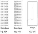
- FIG. 19C illustrates a graphics image.
- the vertical line is to be printed black.
- a circle indicating color ink At the lower end of the vertical line is a circle indicating color ink.
- the black line thus abuts the color ink.
- the black line In CMY color plane data, the black line would be represented as composite black, and the circle as the desired color.
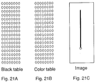
- FIG. 19A shows the contents of a black table
- FIG. 19B shows the contents of a color table after this initial processing has been completed. Only a single bit remains on in the color table (row 12), indicating the color ink (the circle) in the image of FIG. 19C. A series of 1's in the black table now represent the vertical black line in the image. The initial table building corresponding to step 52 in FIG. 10 has been completed.
- step 146 (FIG. 17)
- step 150 fixBlack is called to correct the minimum spacing violation. fixBlack is passed the mask to identify the offending table bit, and the table row and column locations.
- fixBlack receives the parameters: 0001 0000 (mask), 11 (row eleven), 1 (column 1 -- only one column in the example).
- fixBlack moves the corresponding block of data from the K plane back into the color planes, and updates the black and color tables accordingly (see FIG. 18).
- the bit directly above the color bit in FIG. 19B is turned on.
- the corresponding bit in the black table is turned off.
- Next findBlack is called, i.e. the procedure of FIGS. 15-17, to check the black table bits surrounding the new color table bit (in row 11) to detect black adjacent color once again.
- the black table bit in row 11 is now off, and is not at issue.
- But the black table bit in row 10 is detected as being adjacent the color table bit in row 11. Therefore, as before, the corresponding block of data is moved from the K plane back into the color planes.
- the tables are updated, i.e. the color table bit in row 10 is turned on, and the black table bit in row 10 is turned off.
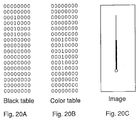
- FIG. 20A black table
- FIG. 20B color table
- the data shown in the tables of FIG. 20 is represented by the image of FIG. 20C. Referring to FIG. 20C, the heavy (lower) portion of the vertical line represents composite black, while the finer (upper) portion of the line represents true black. This illustrates graphically how the composite black is "propagating" up from the color region.
Landscapes
- Engineering & Computer Science (AREA)
- Physics & Mathematics (AREA)
- General Physics & Mathematics (AREA)
- Signal Processing (AREA)
- Mathematical Physics (AREA)
- General Engineering & Computer Science (AREA)
- Multimedia (AREA)
- Theoretical Computer Science (AREA)
- Ink Jet (AREA)
- Color Image Communication Systems (AREA)
- Record Information Processing For Printing (AREA)
- Fax Reproducing Arrangements (AREA)
- Facsimile Image Signal Circuits (AREA)
- Dot-Matrix Printers And Others (AREA)
Applications Claiming Priority (2)
| Application Number | Priority Date | Filing Date | Title |
|---|---|---|---|
| US07/784,498 US5168552A (en) | 1991-10-29 | 1991-10-29 | Color separation in ink jet color graphics printing |
| US784498 | 1991-10-29 |
Publications (3)
| Publication Number | Publication Date |
|---|---|
| EP0540173A2 true EP0540173A2 (fr) | 1993-05-05 |
| EP0540173A3 EP0540173A3 (en) | 1993-06-30 |
| EP0540173B1 EP0540173B1 (fr) | 1998-05-06 |
Family
ID=25132633
Family Applications (1)
| Application Number | Title | Priority Date | Filing Date |
|---|---|---|---|
| EP92308860A Expired - Lifetime EP0540173B1 (fr) | 1991-10-29 | 1992-09-29 | Séparation de couleurs pour impression graphique à jet d'encre |
Country Status (4)
| Country | Link |
|---|---|
| US (1) | US5168552A (fr) |
| EP (1) | EP0540173B1 (fr) |
| JP (1) | JP3294883B2 (fr) |
| DE (1) | DE69225377T2 (fr) |
Cited By (3)
| Publication number | Priority date | Publication date | Assignee | Title |
|---|---|---|---|---|
| EP0590852A3 (en) * | 1992-09-30 | 1994-05-18 | Hewlett Packard Co | Color separation in color graphics printing with limited memory |
| EP0709214A2 (fr) | 1994-10-27 | 1996-05-01 | Canon Kabushiki Kaisha | Appareil d'enregistrement à jet d'encre et méthode utilisant plusieurs sortes d'encre |
| FR2749217A1 (fr) * | 1996-05-30 | 1997-12-05 | Girod Raoul | Correcteur pour imprimante |
Families Citing this family (44)
| Publication number | Priority date | Publication date | Assignee | Title |
|---|---|---|---|---|
| JPH05330086A (ja) * | 1992-06-01 | 1993-12-14 | Fuji Xerox Co Ltd | カラー画像記録装置 |
| US6007182A (en) * | 1992-07-24 | 1999-12-28 | Canon Kabushiki Kaisha | Ink-jet recording method employing inks of different characteristics and apparatus therefor |
| EP0590853B1 (fr) * | 1992-09-30 | 2000-11-08 | Hewlett-Packard Company | Méthode et système de sélection de palettes de couleurs pour imprimante à jet d'encre |
| DE69332251T2 (de) * | 1992-09-30 | 2003-08-07 | Hewlett-Packard Co. (N.D.Ges.D.Staates Delaware), Palo Alto | Verfahren zur Minderung der Tintenmigration für den digitalen Farbdruck |
| CA2102005C (fr) * | 1992-10-30 | 1999-10-12 | Jiro Moriyama | Methode et appareil a jet d'encre pour impression en noir et en couleurs |
| EP0603833B1 (fr) * | 1992-12-22 | 1999-06-30 | Konica Corporation | Appareil de traitement d'images en couleur pour le lissage d'une image |
| DE69418674T2 (de) * | 1993-10-28 | 1999-10-21 | Canon K.K., Tokio/Tokyo | Verfahren und Vorrichtung zur Tintenstrahlaufzeichnung |
| JP3029174B2 (ja) * | 1993-10-28 | 2000-04-04 | キヤノン株式会社 | インクジェット記録装置 |
| US5504846A (en) * | 1993-12-16 | 1996-04-02 | International Business Machines Corporation | Method and apparatus for improved area demarcation in bit mapped image derived from multi-color bit mapped image |
| JP3323625B2 (ja) * | 1994-01-25 | 2002-09-09 | キヤノン株式会社 | カラーインクジェット記録方法 |
| DE69515923T2 (de) | 1994-01-27 | 2000-12-21 | Hewlett Packard Co | Automatische Optimierung von Papierbildern |
| US5731823A (en) * | 1994-01-27 | 1998-03-24 | Hewlett-Packard Company | Automatic optimization of hardcopy output for enhanced appearance and throughput |
| US5553199A (en) * | 1994-05-03 | 1996-09-03 | Eastman Kodak Company | Method and apparatus for calibrating a four color printer |
| DE69519704T2 (de) * | 1994-08-19 | 2001-04-26 | Fuji Xerox Co., Ltd. | Tintenstrahlaufzeichnungsverfahren und dieses benutzendes Gerät |
| IT1284844B1 (it) * | 1994-09-16 | 1998-05-22 | Seiko Epson Corp | Procedimento di stampa a getti di inchiostro a colori |
| JP3175498B2 (ja) * | 1994-10-14 | 2001-06-11 | セイコーエプソン株式会社 | インクジェット式カラー印刷のための黒色領域識別方式 |
| US5767833A (en) * | 1995-06-28 | 1998-06-16 | International Business Machines Corporation | Method and system for providing external bitmap support for devices that support multiple image formats |
| US6015206A (en) * | 1995-11-21 | 2000-01-18 | Lexmark International, Inc. | Bleed avoiding, color ink jet printing |
| US6259536B1 (en) * | 1995-12-27 | 2001-07-10 | Xerox Corporation | Color printing yielding a background dependent black image (i.e. intelligent black) |
| US5809215A (en) * | 1996-04-18 | 1998-09-15 | Lexmark International, Inc. | Method of printing to inhibit intercolor bleeding |
| US5778160A (en) * | 1996-09-24 | 1998-07-07 | Xerox Corporation | Liquid ink printing system having region-dependent image processing |
| US5923821A (en) * | 1996-09-27 | 1999-07-13 | Xerox Corporation | Digital image trapping system |
| US5867179A (en) * | 1996-12-31 | 1999-02-02 | Electronics For Imaging, Inc. | Interleaved-to-planar data conversion |
| US6348978B1 (en) | 1997-07-24 | 2002-02-19 | Electronics For Imaging, Inc. | Method and system for image format conversion |
| US5960163A (en) * | 1998-01-13 | 1999-09-28 | Xerox Corporation | Color bitmap merging of black objects using partially correlated separation maximum value clipping |
| US6118548A (en) * | 1998-02-05 | 2000-09-12 | Canon Kabushiki Kaisha | Replacing true black with process black |
| US6002804A (en) * | 1998-03-26 | 1999-12-14 | Hewlett-Packard Company | Tone dependent variable halftoning with adjustable algorithm selection |
| US6285462B1 (en) | 1998-11-13 | 2001-09-04 | Xerox Corporation | Intelligent GCR/UCR process to reduce multiple colorant moire in color printing |
| US6244687B1 (en) | 1999-03-22 | 2001-06-12 | Hewlett-Packard Company | Mixing overprinting and underprinting of inks in an inkjet printer to speed up the dry time of black ink without undesirable hue shifts |
| US6132021A (en) * | 1999-06-10 | 2000-10-17 | Hewlett-Packard Company | Dynamic adjustment of under and over printing levels in a printer |
| US7110140B1 (en) | 1999-08-05 | 2006-09-19 | Xerox Corporation | Methods and systems for undercolor reduction |
| US7050195B1 (en) * | 2000-04-20 | 2006-05-23 | Hewlett-Packard Development Company, L.P. | Printed medium data storage |
| US7265856B1 (en) | 2001-03-21 | 2007-09-04 | Lexmark International Inc. | Method and system for receiving and processing multiple compressed print data streams |
| US20030081244A1 (en) * | 2001-10-30 | 2003-05-01 | Clouthier Scott C. | Method and apparatus for processing data in an imaging device |
| US7817302B2 (en) * | 2004-03-26 | 2010-10-19 | Lexmark International, Inc. | Optimizing raster operation functions during print job processing |
| US20050213142A1 (en) * | 2004-03-26 | 2005-09-29 | Clark Raymond E | Optimization techniques during processing of print jobs |
| US7835030B2 (en) * | 2004-03-26 | 2010-11-16 | Lexmark International, Inc. | Processing print jobs |
| US7385729B2 (en) * | 2004-03-26 | 2008-06-10 | Lexmark International, Inc. | Optimization techniques during processing of print jobs |
| US7234791B2 (en) * | 2005-04-26 | 2007-06-26 | Eastman Kodak Company | Reducing ink bleed artifacts |
| US7652795B2 (en) | 2005-12-06 | 2010-01-26 | Eastman Kodak Company | Reducing ink bleed artifacts |
| US8665482B2 (en) * | 2007-03-01 | 2014-03-04 | Konica Minolta Laboratory U.S.A., Inc. | Raster image processor using a self-tuning banding mode |
| US8422082B2 (en) | 2009-07-22 | 2013-04-16 | Eastman Kodak Company | Reducing ink bleed artifacts for RGB images |
| DE102018201669A1 (de) | 2017-03-21 | 2018-09-27 | Heidelberger Druckmaschinen Ag | Verfahren zum Erhalt des Schwarzaufbaus von Objekten |
| DE102023118821A1 (de) * | 2023-07-17 | 2025-01-23 | Heidelberger Druckmaschinen Aktiengesellschaft | Farbmanagement für maschinell auslesbare optische Codes auf Druckerzeugnissen |
Family Cites Families (7)
| Publication number | Priority date | Publication date | Assignee | Title |
|---|---|---|---|---|
| EP0506144B1 (fr) * | 1985-06-14 | 1996-10-16 | Dai Nippon Insatsu Kabushiki Kaisha | Méthode et dispositif d'enregistrement thermique multicolore par sublimation |
| US4896275A (en) * | 1987-07-10 | 1990-01-23 | Bull Hn Information Systems Inc. | Full page graphics image display data reduction |
| JPH01198870A (ja) * | 1987-10-08 | 1989-08-10 | Ricoh Co Ltd | デジタルカラー画像処理装置 |
| JP2713935B2 (ja) * | 1987-12-29 | 1998-02-16 | キヤノン株式会社 | 画像処理方法 |
| JPH01228376A (ja) * | 1988-03-09 | 1989-09-12 | Minolta Camera Co Ltd | 階調表現方法 |
| US4959790A (en) * | 1988-06-28 | 1990-09-25 | F & S Corporation Of Columbus, Georgia | Apparatus and method for producing color corrected reproduction of colored original images |
| US5012257A (en) * | 1990-03-16 | 1991-04-30 | Hewlett-Packard Company | Ink jet color graphics printing |
-
1991
- 1991-10-29 US US07/784,498 patent/US5168552A/en not_active Expired - Lifetime
-
1992
- 1992-09-29 EP EP92308860A patent/EP0540173B1/fr not_active Expired - Lifetime
- 1992-09-29 DE DE69225377T patent/DE69225377T2/de not_active Expired - Lifetime
- 1992-10-29 JP JP31399692A patent/JP3294883B2/ja not_active Expired - Fee Related
Cited By (6)
| Publication number | Priority date | Publication date | Assignee | Title |
|---|---|---|---|---|
| US5475800A (en) * | 1991-10-29 | 1995-12-12 | Hewlett-Packard Company | Color separation in color graphics printing with limited memory |
| EP0590852A3 (en) * | 1992-09-30 | 1994-05-18 | Hewlett Packard Co | Color separation in color graphics printing with limited memory |
| EP0709214A2 (fr) | 1994-10-27 | 1996-05-01 | Canon Kabushiki Kaisha | Appareil d'enregistrement à jet d'encre et méthode utilisant plusieurs sortes d'encre |
| EP0709214A3 (fr) * | 1994-10-27 | 1997-12-03 | Canon Kabushiki Kaisha | Appareil d'enregistrement à jet d'encre et méthode utilisant plusieurs sortes d'encre |
| US5975678A (en) * | 1994-10-27 | 1999-11-02 | Canon Kabushiki Kaisha | Ink jet recording apparatus and method using plural types of ink |
| FR2749217A1 (fr) * | 1996-05-30 | 1997-12-05 | Girod Raoul | Correcteur pour imprimante |
Also Published As
| Publication number | Publication date |
|---|---|
| US5168552A (en) | 1992-12-01 |
| DE69225377D1 (de) | 1998-06-10 |
| DE69225377T2 (de) | 1998-09-03 |
| EP0540173A3 (en) | 1993-06-30 |
| JPH05276373A (ja) | 1993-10-22 |
| JP3294883B2 (ja) | 2002-06-24 |
| EP0540173B1 (fr) | 1998-05-06 |
Similar Documents
| Publication | Publication Date | Title |
|---|---|---|
| US5168552A (en) | Color separation in ink jet color graphics printing | |
| US5475800A (en) | Color separation in color graphics printing with limited memory | |
| US5635967A (en) | Image processing method to reduce marking material coverage in printing processes | |
| US6490055B1 (en) | Printing apparatus with execution of software rendering and hardware rendering | |
| US7692813B2 (en) | Image processing apparatus and method, and storage medium | |
| EP1467556B1 (fr) | Procédé, appareil et programme de traitement d'image pour produire des images achromatiques de haute qualité | |
| JPH1115966A (ja) | ハーフトーン方法 | |
| US20050213114A1 (en) | Optimization techniques during processing of print jobs | |
| WO1993022871A1 (fr) | Procede et systeme de reproduction de demi-teintes en couleur | |
| JP4215842B2 (ja) | カラー画像の印刷方法 | |
| US6429950B1 (en) | Method and apparatus for applying object characterization pixel tags to image data in a digital imaging device | |
| US8339667B2 (en) | Optimizing to-be printed objects during print job processing | |
| EP0532208B1 (fr) | Imprimante bicolore | |
| US6259536B1 (en) | Color printing yielding a background dependent black image (i.e. intelligent black) | |
| US6445463B1 (en) | Image processing method to reduce marking material coverage in printing processes | |
| US6880907B2 (en) | Method of maintaining edge quality in ink jet printing | |
| US5588093A (en) | Color mapping to preserve detail | |
| JPH08112917A (ja) | インクジェット式カラー印刷のための黒色領域識別方式 | |
| US6400467B1 (en) | Method and apparatus for rendering halftone areas of an image with continuous boundaries | |
| JPH05238074A (ja) | 色と本文によるプリンタ頁の構築方法 | |
| EP0782097B1 (fr) | Méthode et système pour l'impression digitale multicolore | |
| AU761578B2 (en) | Black text printing from page description languages | |
| EP0817122B1 (fr) | Filtre et opérations de trame | |
| US5848180A (en) | Color bitmap generation with background dependent black objects | |
| JPH04139589A (ja) | 図形処理装置 |
Legal Events
| Date | Code | Title | Description |
|---|---|---|---|
| PUAI | Public reference made under article 153(3) epc to a published international application that has entered the european phase |
Free format text: ORIGINAL CODE: 0009012 |
|
| AK | Designated contracting states |
Kind code of ref document: A2 Designated state(s): DE FR GB IT |
|
| PUAL | Search report despatched |
Free format text: ORIGINAL CODE: 0009013 |
|
| AK | Designated contracting states |
Kind code of ref document: A3 Designated state(s): DE FR GB IT |
|
| 17P | Request for examination filed |
Effective date: 19931208 |
|
| 17Q | First examination report despatched |
Effective date: 19960206 |
|
| GRAG | Despatch of communication of intention to grant |
Free format text: ORIGINAL CODE: EPIDOS AGRA |
|
| GRAG | Despatch of communication of intention to grant |
Free format text: ORIGINAL CODE: EPIDOS AGRA |
|
| GRAG | Despatch of communication of intention to grant |
Free format text: ORIGINAL CODE: EPIDOS AGRA |
|
| GRAH | Despatch of communication of intention to grant a patent |
Free format text: ORIGINAL CODE: EPIDOS IGRA |
|
| GRAH | Despatch of communication of intention to grant a patent |
Free format text: ORIGINAL CODE: EPIDOS IGRA |
|
| GRAA | (expected) grant |
Free format text: ORIGINAL CODE: 0009210 |
|
| AK | Designated contracting states |
Kind code of ref document: B1 Designated state(s): DE FR GB IT |
|
| ITF | It: translation for a ep patent filed | ||
| REF | Corresponds to: |
Ref document number: 69225377 Country of ref document: DE Date of ref document: 19980610 |
|
| ET | Fr: translation filed | ||
| PLBE | No opposition filed within time limit |
Free format text: ORIGINAL CODE: 0009261 |
|
| 26N | No opposition filed | ||
| REG | Reference to a national code |
Ref country code: GB Ref legal event code: 732E |
|
| REG | Reference to a national code |
Ref country code: FR Ref legal event code: TP |
|
| REG | Reference to a national code |
Ref country code: GB Ref legal event code: IF02 |
|
| PGFP | Annual fee paid to national office [announced via postgrant information from national office to epo] |
Ref country code: IT Payment date: 20060930 Year of fee payment: 15 |
|
| PGFP | Annual fee paid to national office [announced via postgrant information from national office to epo] |
Ref country code: FR Payment date: 20070917 Year of fee payment: 16 |
|
| REG | Reference to a national code |
Ref country code: FR Ref legal event code: ST Effective date: 20090529 |
|
| PG25 | Lapsed in a contracting state [announced via postgrant information from national office to epo] |
Ref country code: IT Free format text: LAPSE BECAUSE OF NON-PAYMENT OF DUE FEES Effective date: 20070929 |
|
| PG25 | Lapsed in a contracting state [announced via postgrant information from national office to epo] |
Ref country code: FR Free format text: LAPSE BECAUSE OF NON-PAYMENT OF DUE FEES Effective date: 20080930 |
|
| PGFP | Annual fee paid to national office [announced via postgrant information from national office to epo] |
Ref country code: DE Payment date: 20100929 Year of fee payment: 19 |
|
| PGFP | Annual fee paid to national office [announced via postgrant information from national office to epo] |
Ref country code: GB Payment date: 20110926 Year of fee payment: 20 |
|
| REG | Reference to a national code |
Ref country code: GB Ref legal event code: 732E Free format text: REGISTERED BETWEEN 20120329 AND 20120404 |
|
| REG | Reference to a national code |
Ref country code: DE Ref legal event code: R071 Ref document number: 69225377 Country of ref document: DE |
|
| REG | Reference to a national code |
Ref country code: DE Ref legal event code: R071 Ref document number: 69225377 Country of ref document: DE |
|
| REG | Reference to a national code |
Ref country code: GB Ref legal event code: PE20 Expiry date: 20120928 |
|
| PG25 | Lapsed in a contracting state [announced via postgrant information from national office to epo] |
Ref country code: GB Free format text: LAPSE BECAUSE OF EXPIRATION OF PROTECTION Effective date: 20120928 |