EP0540195A2 - Radioréception numérique en quadrature avec traitement en deux étapes - Google Patents
Radioréception numérique en quadrature avec traitement en deux étapes Download PDFInfo
- Publication number
- EP0540195A2 EP0540195A2 EP92309141A EP92309141A EP0540195A2 EP 0540195 A2 EP0540195 A2 EP 0540195A2 EP 92309141 A EP92309141 A EP 92309141A EP 92309141 A EP92309141 A EP 92309141A EP 0540195 A2 EP0540195 A2 EP 0540195A2
- Authority
- EP
- European Patent Office
- Prior art keywords
- signal
- digital
- analogy
- detector
- complex
- Prior art date
- Legal status (The legal status is an assumption and is not a legal conclusion. Google has not performed a legal analysis and makes no representation as to the accuracy of the status listed.)
- Granted
Links
Images


Classifications
-
- H—ELECTRICITY
- H04—ELECTRIC COMMUNICATION TECHNIQUE
- H04B—TRANSMISSION
- H04B1/00—Details of transmission systems, not covered by a single one of groups H04B3/00 - H04B13/00; Details of transmission systems not characterised by the medium used for transmission
- H04B1/06—Receivers
- H04B1/16—Circuits
Definitions
- the present invention relates in general to a digital radio receiver employing quadrature signal processing and more specifically to a digital radio receiver for reproducing AM stereo radio signals.
- radio services such as AM and FM
- AM and FM are broadcast as a modulated analogue signal.
- Certain radio receivers have been employed which convert the received analogue signal into a digital signal for performing digital signal processing (DSP) to thereby realise various advantages, such as circuit integration, reduced size, exact operation, minimal adjustments, and the ability to combine signal processing with other audio functions (e.g., tone control, concert hall emulation, and equalisation) also performed in DSP.
- DSP digital signal processing
- the cost of implementing a particular receiver using DSP components increases with the amount of processing required to perform the desired functions.
- the processing load of a particular DSP system depends on the functions implemented and on the number of samples in the digital signal which must be processed in a given amount of time, i.e., the sampling rate f s in samples per second.
- the sampling rate f s must be at least two times the frequency bandwidth of the sampled signal to avoid distortion.
- the sampled signal is typically an intermediate frequency (IF) signal from an analogy tuner stage.
- the analogy IF is centred at a non-zero frequency and is typically 455 kHz in an AM receiver and l0.7 MHz in an FM receiver.
- the IF signal is converted to a digital IF signal using an analogy-to-digital (A/D) converter.
- A/D analogy-to-digital
- the digital IF signal It is known to reduce digital processing load by representing the digital IF signal as a quadrature signal with an in-phase (I) component and a quadrature-phase (Q) component. It is preferable to form the I and Q signals after conversion to digital signals due to the difficulties encountered in matching the I and Q signal path characteristics in analogy circuitry.
- U.S. Patent 4,893,316 to Janc et al discloses a digital signal processing receiver employing quadrature signals. Janc et al employs two injection (i.e., mixing) signals from a digital quadrature local oscillator for mixing with the digital signal to produce the I and Q signal components comprising a nominal zero-Hertz intermediate frequency.
- U.S. Patent 4,592,074 to Whikehart teaches a technique for forming I and Q components simultaneously with a reduction in sampling rate in a digital filter without the need for actual injection signals.
- the values for the injection signal become repeating sine and cosine sequences of the values l, 0, and -l, which can be directly implemented in the digital filter without an oscillator.
- An analogy-to-digital converter operates at a sampling rate f s to convert an analogy IF signal to a first digital IF signal comprised of a plurality of samples.
- the first digital IF signal has a centre frequency about equal to f s /4.
- a concurrent complex-mixing, filtering, and sample-rate reducing means generates a complex IF signal having a near-zero centre frequency within a frequency range from -f s /8 to +f s /8.
- the complex IF signal has an in-phase component (I) and a quadrature-phase (Q), each being formed from weighted alternate samples of the first digital IF signal according to a set of predetermined filter-tap weights.
- the predetermined weights correspond to a complex mixing signal having a frequency equal to f s /4 and corresponding to a reduction in sampling rate by a whole multiple of 4.
- a complex mixing means is coupled to the concurrent means for synchronously detecting the complex IF signal.
- the complex mixing means includes a variable oscillator producing sine and cosine signals locked to the frequency and phase of the complex IF signal.
- the received radio signals are AM stereo signals broadcast in the C-QUAM format.
- an antenna l0 receives a radio broadcast wave and a resulting analogy antenna signal is provided to an analogy tuner 11.
- the output from analogy tuner 11 is coupled to an anti-aliasing filter l2 and to an A/D converter l3. If the output of analogy tuner 11 is sufficiently band limited, then anti-aliasing filter l2 is not required prior to digital conversion by A/D converter l3.
- A/D converter l3 is clocked at a sampling rate f s to provide digital samples at the sampling rate to a digital signal processing (DSP) block l4.
- DSP digital signal processing
- the radio signal represented by the digital samples is demodulated using DSP techniques. Other processing, including stereo decoding, is also performed in DSP block 14 to produce left and right stereo signals.
- D/A converters l5 and l6 convert the stereo signals to analogy form.
- D/A converters 15 and 16 receive a clocking signal at sampling rate f s .
- Figure 2 demonstrates a prior art technique for reducing the processing rate required for DSP block l4.
- Digital samples from A/D converter 13 are provided to digital mixers l7 and l8.
- a digital quadrature oscillator (not shown) provides quadrature mixing signals COS( ⁇ t) and SIN( ⁇ t) to digital mixers l7 and l8, respectively.
- the resulting mixer outputs are provided to respective decimation filters 20 and 2l having respective I and Q outputs comprising digital samples at a lower sampling rate f s '.
- the digital injections (i.e, mixing) signals from the digital quadrature oscillator are provided at sampling rate f s (i.e., the same sampling rate as the IF signal).
- sampling rate f s i.e., the same sampling rate as the IF signal.
- the injection signals can be characterised by repeating sine and cosine sequences of the values l, 0, and -l. This relationship is utilised in previously mentioned U.S. Patent 4,592,074 wherein the sine and cosine sequences are implemented as part of a digital filter so that the digital mixers l7 and l8 are not required.
- samples are provided to a negator 22 for selectively negating the samples in response to a select signal corresponding to the appropriate sign of the sine and cosine injections.
- the selectively negated samples are provided to a gate 23 and a gate 25.
- a clock signal is provided to a control input of gate 23 for transmitting alternate samples from negator 22 to a decimation filter 24 which reduces the sampling rate and provides an in-phase I digital output signal.
- the clock signal is inverted by an inverter 26 for controlling gate 25 to transmit the other alternate samples to a decimation filter 27 for producing a quadrature-phase Q digital output signal at a reduced sampling rate f s '.
- the intermediate frequency and the injection frequency are both one-quarter of the sampling rate, then the I and Q components are translated to a nominal zero Hertz (i.e., baseband) intermediate frequency signal.
- the injection frequency is at a fixed frequency, the mixing operation cannot be phased locked to the incoming IF signal (i.e., synchronous detection is not obtainable).
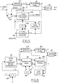
- Figure 5 shows a conventional analogy receiver for processing AM stereo signals received in the compatible quadrature amplitude modulation (C-QUAM) format.
- C-QUAM quadrature amplitude modulation
- a C-QUAM IF signal is provided to an envelope detector 30 which provides an envelope signal equal to l+L+R to a DC blocking filter 3l. After the DC offset is removed in DC blocking filter 3l, an L+R signal is provided to a stereo decoder matrix 32 for producing right and left channel audio outputs.
- the remainder of Figure 5 converts the C-QUAM IF signal to a QUAM IF signal in order to generate the difference signal L-R for input to matrix 32.
- the C-QUAM IF signal is provided to a variable gain amplifier 33.
- the output of amplifier 33 is coupled to an in-phase synchronous detector 34 and a quadrature-phase synchronous detector 36.
- the output of detector 34 provides an output signal corresponding to l+L+R+ERROR to one input of a difference amplifier 35.
- the other input of difference amplifier 35 receives the l+L+R signal from envelope detector 30.
- Difference amplifier 35 is a high gain amplifier and provides an ERROR signal to the gain control input of variable gain amplifier 33. Since difference amplifier 35 is a high gain amplifier, the output of amplifier 33 corresponds to a QUAM signal.
- phase detector 37 The output of Q-phase synchronous detector 36 is connected to matrix 32 and to a phase detector 37.
- the QUAM signal from amplifier 33 is connected to another input of phase detector 37.
- the output of phase detector 37 is connected to a voltage-controlled oscillator (VCO) 38 which provides a cosine signal to in-phase synchronous detector 34 and a sine signal (phase shifted by 90° with respect to the cosine signal) to quadrature-phase synchronous detector 36.
- VCO voltage-controlled oscillator
- FIG. 6 shows a preferred embodiment of the present invention for implementing a synchronous detector using digital signal processing at a reduced processing load.
- Analogy IF signals are provided to an A/D converter 40 and converted to a digital IF signal with a centre frequency f d .
- the digital samples at a sampling rate f s are input to a concurrent filter 4l.
- Filter 4l provides quadrature mixing and downsampling functions.
- the quadrature mixing function preferably results in a shifted IF centre frequency near zero, but not necessarily exactly equal to zero.
- the sample-rate reduced, near-zero Hertz I and Q signals from filter 4l are provided to a quadrature mixer 42 which is phase locked to provide synchronous detection by means of a loop filter 43 and a digital VCO 44.
- concurrent filter 4l reduces the processing load by performing a quadrature mixing operation to create a complex IF signal having an in-phase component I and a quadrature-phase component Q.
- the complex IF signal now at a reduced sampling rate, undergoes a second complex mixing operation in quadrature mixer 42.
- quadrature mixer 42 During demodulation of a C-QUAM signal, quadrature mixer 42 becomes locked to the near-zero-Hertz complex IF signal and produces at its outputs a synchronous-detector I signal and a synchronous-detector Q signal which together form a zero Hertz IF signal.
- VCO 44 is implemented using known DSP techniques (see, e.g., Motorola Application Note, "Digital Sine-Wave Synthesis Using the DSP56001").
- FIG. 6 shows the two-step processing of the invention in the context of an AM stereo receiver for signals broadcast in the C-QUAM format.
- An envelope detector 45 receives the near-zero-Hertz complex IF signal and determines the envelope by calculating the square root of the sum of the squares of the in-phase and quadrature-phase components.
- the detected envelope is provided to a DC blocking filter 46 which may be comprised of a lowpass filter for isolating the DC component and a summer for subtracting out the DC component from the envelope signal.
- An L+R audio signal is provided from DC blocking filter 46 to a stereo decoder matrix 47 which generates left and right stereo signals.
- the detected envelope from envelope detector 45 is also provided to a conversion block 48 which further receives from mixer 42 the synchronous-detector I signal and the synchronous-detector Q signal from quadrature mixer 42.
- An L-R audio signal is obtained from the synchronous-detector Q signal by converting it to a QUAM signal.
- the L-R signal is provided to matrix 47 for stereo decoding and to loop filter 43 for implementing a phase-locked loop in conjunction with VCO 44.
- loop filter 43 may directly employ the synchronous-detector Q signal as its sole input signal for closing the phase-locked loop.
- the conversion to QUAM performed by conversion block 48 can be implemented according to various methods, e.g., the implicit method, the inverse function method, and the divider method, which will be described later with reference to Figures 22-24.
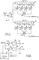
- Concurrent filter 4l for providing quadrature mixing and downsampling functions is shown in greater detail in Figure 7.
- Concurrent filter 41 consists of separate I and Q parallel filters of the finite-impulse-response (FIR) type.
- An FIR filter uses a tapped delay line (i.e., shift register) to store past input samples which are multiplied by filter-tap weights and summed to form an output sample.
- the filter must be x*4 taps in length, where x is an integer greater than zero. Thus, the smallest filter decimating by 4 would have 4 taps.
- each filter mathematically corresponds to 8-tap filters, although each filter actually needs only 4 taps because of a hardware simplification resulting in the present invention from the fact that the other 4 taps are always multiplied by zero, as will be discussed later.
- a 4-tap filter decimating by 4 could be employed with only 2 taps being actually needed in the separate I and Q portions of the filter, resulting in the smallest possible filter.
- the size of filter employed depends on the specific filtering desired in a particular design.
- digital samples are alternately provided to a pair of shift registers 50 and 5l using a demultiplexer 52, for example.
- Shift register 50 includes elements 60, 62, 64 and 66 for shifting in two samples for calculating every I output sample.
- Shift register 5l includes elements 70, 72, 74, and 76 for shifting in two samples for calculating every Q output sample.
- a sequence of eight digital samples designated a0, a l ,... a7 are passed through demultiplexer 52 into shift registers 50 and 5l in the 8-tap filters as shown.
- a set of four input samples passed through demultiplexer 52 are thus digitally filtered to provide a single I-and-Q-pair output sample (i.e., a decimation by 4).
- a multiplier 6l receives digital sample a0 for multiplication by a constant c7.
- a multiplier 63 receives digital sample a2 for multiplication by a constant -c5.
- a multiplier 65 receives digital sample a4 for multiplication by a constant c3.
- a multiplier 67 receives digital sample a6 for multiplication by a constant -c1.
- multipliers 6l, 63, 65, and 67 are applied to a summer 68, the output of which provides a single sample of the in-phase component I of the complex IF signal at a sampling rate f s ' equal to f s /4.
- multipliers 7l, 73, 75 and 77 multiply digital samples a l , a3, a5, and a7 by constants c6, -c4, c2, and -c0, respectively.
- the products are summed in a summer 78 to provide the quadrature-phase component Q of the complex IF signal at a sampling rate f s ' equal to f s /4.
- Figure 8 illustrates the mathematically equivalent functions which are concurrently implemented in the filter of Figure 7.
- a pair of mixers 53 and 54 receive cosine and sine injection signals, respectively, from a digital quadrature oscillator 55 having a frequency of f s /4.
- the cosine product is provided to a lowpass filter 56 and a decimation-by-4 filter 57 (resampling at f s /4) to provide the in-phase component I.
- the sine product from mixer 54 is provided to a lowpass filter 58 and a decimation-by-4 filter 59 to produce the quadrature-phase component Q.
- the functions may be concurrently performed in the filter of Figure 7 where the number of taps and the values of the filter-tap weights depend on the particular decimation and filtering to be performed.
- Lowpass filters 56 and 58 perform an anti-aliasing function which is performed in the concurrent filter by adjustment of the filter-tap weights (i.e., constants c0 to c7).
- Quadrature mixing is obtained by negation of certain weights and by dropping one-half of the taps otherwise required (i.e., not multiplying and summing alternate samples in each separate I and Q portion of the filter since they would only add zero to the sum).
- the concurrent filter 4l in Figure 7 is a decimation filter with eight actual taps having respective multipliers c0 to c7.
- Filter-tap weights c0 to c7 are determined in a conventional manner for the anti-aliasing and decimation functions to be performed in a particular receiver.
- I c0*0 + c1*(-a6) + c2*0 + c3*a4 + c4*0 + c5*(-a2) + c6*0 + c7*a0
- Q c0*(-a7) + c1*0 + c2*a5 + c3*0 + c4*(-a3) + c5*0 + c6*a1 + c7*0 .
- Filter coefficients c0 to c7 are determined according to known finite impulse response (FIR) decimation filter design methods.
- the foregoing concurrent filter may be obtained using a decimation filter having any number of taps which is a multiple of four.
- an FIR filter having 20 taps may be preferably employed to provide a 20 kHz lowpass filter with a 60 dB stopband and .5 dB ripple in the passband up to 7.5 kHz.
- Figures 9-2l show frequency spectra of various signals present in Figure 6.
- the analogy intermediate frequency provided from an analogy tuner to an A/D converter has a frequency spectrum component 80 having a centre frequency f a .
- a mirror image frequency component 80' is shown with a negative frequency to allow consideration of complex signals. For purely real signal, the negative frequency component will be a mirror image of the positive frequency component.
- Figure l0 shows the frequency spectrum of the sampling operation of the A/D converter which consists of all integer multiples of sampling rate f s including zero Hertz.
- the digital samples from the A/D converter comprise a digital IF signal having a frequency spectrum with a positive frequency component 8l having a centre frequency f d and a mirror image negative component 8l'. Further pairs of frequency components appear around each integer multiple of f s since analogy-to-digital conversion can be considered to be a convolution of the frequency components shown in Figures 9 and l0.
- the digital IF signal In order to be represented in the digital domain, the digital IF signal must have a complete frequency component 81 or 81' contained in the frequency range from -f s /4 to +f s /4.
- Figure l2 shows components 8l and 8l' on an expanded frequency scale, such expanded scale being used for the remainder of Figures l2-2l.
- Hash-marks on Figures 12-21 are used to indicate that the spectrum within the hash-marks repeats in both frequency directions.
- Figure l3 shows the injection of a mixing signal at one-quarter of the sampling rate to translate frequency spectrum 8l shown in Figure l2 to a near-zero IF spectrum 82 shown in Figure l4.
- the injection signal is shown at -f s /4 in Figure l3.
- Spectrum component 81' is translated to 82' as shown in Figure 14.
- An injection signal at +f s /4 could also be used with the resulting spectrum in Figure 14 being flipped around with respect to zero Hertz.
- Figure l5 shows a passband 83 corresponding to the lowpass (anti-aliasing) filtering function of the concurrent filter of the present invention.
- Passband 83 is determined by filter weights c0 to c7.
- the spectrum of the output of the lowpass filter function is shown in Figure l6 where only spectral component 82 of the complex IF signal remains.
- the complex signal shown in Figure l6 Prior to output from the concurrent filter, the complex signal shown in Figure l6 is decimated by 4 (i.e., resampled at a sampling frequency f s ' equal to f s /4) as shown in Figure l7.
- the decimated output has a spectrum shown in Figure l8 with a component 83 which repeats at multiples of f s /4. As shown in Figure l9, only the component 83 between -f s /8 and f s /8 is considered.
- a changing injection frequency f c which is synchronous with the instantaneous phase of the complex IF signal and generated by a phase-locked loop is shown in Figure 20.
- Mixing of the signals of Figure l9 and Figure 20 in the synchronous detector of the present invention results in a zero-Hertz demodulated signal having a spectrum 84 shown in Figure 2l.
- An application of the present invention to an AM stereo C-QUAM receiver is shown in greater detail in Figure 22.
- An antenna 85 provides RF broadcast signals to an analogy tuner 86.
- a bandlimited IF signal having a centre intermediate frequency of 47.5 kHz is provided from analogy tuner 86 to A/D converter 40.
- A/D converter 40 operates with a sampling rate f s equal to l52 kHz and, therefore, provides a first digital IF signal also at an intermediate frequency of 47.5 kHz.
- Concurrent filter 4l, synchronous detector 42, loop filter 43, and VCO 44 operate in the same manner as described with reference to Figure 6.
- the complex IF signal from concurrent filter 4l has a sampling rate at f s /4 which equals 38 kHz in this example.
- the complex in-phase component I and quadrature-phase component Q have an intermediate frequency of 9.5 kHz.
- Synchronous detector 42 converts this 9.5 kHz IF frequency to a zero-Hertz IF consisting of a synchronous-detector I signal and a synchronous-detector Q signal.
- Figure 22 shows an alternate connection of an envelope detector 87 for receiving the first digital IF signal from A/D converter 40 (i.e., a real IF signal rather than a complex IF signal). Due to the higher frequency of this IF signal, envelope detector 87 performs envelope detection using the more conventional manner of providing a peak detection and lowpass filter function rather than determining the square root of the sum of the squares of the complex signals as used in Figure 6.
- the receiver shown in Figure 22 employs the implicit calculation method for converting the demodulated C-QUAM signals to a QUAM format.
- a lowpass filter 90 filters the l+L+R signal from envelope detector 87 to generate its DC component (related to the signal strength of the received signal) and provides an output to an inverting input on a summer 9l for subtracting the DC component from the synchronous-detector I signal from synchronous detector 42.
- the output of summer 9l is connected to one input of a multiplier 92 which has its output connected to an inverting input of a summer 93.
- a non inverting input of summer 93 receives the output from envelope detector 87.
- the output of summer 93 provides a correction signal for converting the C-QUAM signals to QUAM signals.
- the correction signal has a magnitude equal to 1/COS ⁇ , where ⁇ represents the phase encoded stereo information as defined by the C-QUAM format.
- the correction signal is provided to the remaining input of multiplier 92 and to one input of a multiplier 94.
- Multiplier 94 receives the synchronous-detector Q signal from synchronous detector 42 at its remaining input and produces a L-R signal at its output which is a corrected QUAM signal.
- the L+R signal from DC blocking filter 46 and the L-R signal from multiplier 94 are coupled to respective inputs of stereo decoder matrix 47.
- the L-R signal from multiplier 94 is further connected to loop filter 43 and to a pilot detector 95.
- a stereo detect signal is provided from pilot detector 95 to blend control 96 when a stereo pilot carrier is present in the L-R signal.
- Blend control 96 controls the stereo blend of stereo decoder matrix 47 based on the detection of the stereo pilot and on a signal strength signal obtained from analogy tuner 86 through an A/D converter 97.
- a left stereo signal L is provided from stereo decoder matrix 47 to a digital anti-aliasing lowpass filter l00, a D/A converter l0l, an analogy lowpass filter l02 and a left channel speaker (not shown).
- a right stereo signal R is provided to a digital anti-aliasing lowpass filter l03, a D/A converter l04, an analogy lowpass filter l05 and a right channel speaker (not shown).
- D/A converters l0l and l04 receive a sampling rate signal corresponding to the final sampling rate f s ' of 38 kHz (i.e., f s /4).
- Filters 100 and 103 are not necessary in this specific example and are only shown in connection with the possibility that it may be desired in some instances to increase the sampling rate for D/A conversion. In that event, filters 100 and 103 simplify the analogy filtering that is required after D/A conversion. Filters 100 and 103 are not used if no sampling rate increase is performed.
- Figure 23 shows an alternate embodiment of the invention wherein conversion from C-QUAM to QUAM is obtained using the inverse function method.
- the output of envelope detector 45 is provided to an input of a summer 110 having its output connected to a high gain amplifier 111.
- the output of amplifier 111 provides a l/COS ⁇ correction signal to an input of a multiplier 112 and an input of a multiplier 113.
- Multiplier 112 has another input connected to the synchronous-detector I signal from synchronous detector 42.
- the output of multiplier 112 is connected to an inverting input of summer 110.
- Multiplier 113 has another input connected to receive the synchronous-detector Q signal from synchronous detector 42.
- the output from multiplier 113 provides the corrected QUAM signal corresponding to the L-R signal.
- Figure 24 illustrates the divider method for converting C-QUAM to QUAM.
- a divider 115 is connected to synchronous detector 42 and it divides the synchronous-detector Q signal by the synchronous-detector I signal. Division is implemented in DSP using shift and subtract operations. The result of the division is provided to one input of a multiplier 116 for multiplying the divider signal by the envelope detector signal to produce the corrected L-R signal.
Landscapes
- Engineering & Computer Science (AREA)
- Computer Networks & Wireless Communication (AREA)
- Signal Processing (AREA)
- Stereo-Broadcasting Methods (AREA)
Applications Claiming Priority (2)
| Application Number | Priority Date | Filing Date | Title |
|---|---|---|---|
| US783470 | 1991-10-28 | ||
| US07/783,470 US5222144A (en) | 1991-10-28 | 1991-10-28 | Digital quadrature radio receiver with two-step processing |
Publications (3)
| Publication Number | Publication Date |
|---|---|
| EP0540195A2 true EP0540195A2 (fr) | 1993-05-05 |
| EP0540195A3 EP0540195A3 (en) | 1994-05-11 |
| EP0540195B1 EP0540195B1 (fr) | 2000-05-10 |
Family
ID=25129347
Family Applications (1)
| Application Number | Title | Priority Date | Filing Date |
|---|---|---|---|
| EP92309141A Expired - Lifetime EP0540195B1 (fr) | 1991-10-28 | 1992-10-05 | Radioréception numérique en quadrature avec traitement en deux étapes |
Country Status (3)
| Country | Link |
|---|---|
| US (1) | US5222144A (fr) |
| EP (1) | EP0540195B1 (fr) |
| DE (1) | DE69231027T2 (fr) |
Cited By (5)
| Publication number | Priority date | Publication date | Assignee | Title |
|---|---|---|---|---|
| GB2282286A (en) * | 1993-08-20 | 1995-03-29 | Motorola Inc | A radio device with spectral inversion |
| WO1996010290A1 (fr) * | 1994-09-27 | 1996-04-04 | Blaupunkt-Werke Gmbh | Demodulateur d'amplitude |
| WO1997020449A1 (fr) * | 1995-11-29 | 1997-06-05 | Sound-Ball | Procede pour la restitution des bruits de ballon lors d'une manifestation sportive et ballon pour la mise en oeuvre d'un tel dispositif |
| WO1998042158A1 (fr) * | 1997-03-19 | 1998-09-24 | Sound-Ball S.A.R.L. | Procede pour la restitution des bruits d'un accessoire sportif et article de sport pour la mise en oeuvre d'un tel dispositif |
| EP1115197A3 (fr) * | 1999-12-21 | 2003-03-26 | Mitsubishi Denki Kabushiki Kaisha | Démodulateur numérique pour stéréo-FM, et procédé |
Families Citing this family (81)
| Publication number | Priority date | Publication date | Assignee | Title |
|---|---|---|---|---|
| US5357544A (en) * | 1992-07-21 | 1994-10-18 | Texas Instruments, Incorporated | Devices, systems, and methods for composite signal decoding |
| WO1994005089A1 (fr) * | 1992-08-25 | 1994-03-03 | Wireless Access, Inc. | Filtre de decimation convenant a de multiples protocoles |
| US5412638A (en) * | 1993-06-02 | 1995-05-02 | Vimak Corporation | Method for correcting errors in digital audio data |
| US5490173A (en) * | 1993-07-02 | 1996-02-06 | Ford Motor Company | Multi-stage digital RF translator |
| DE4340012B4 (de) * | 1993-11-24 | 2004-04-22 | Blaupunkt-Werke Gmbh | Demodulator |
| US5640670A (en) * | 1994-12-08 | 1997-06-17 | Broadcom Corporation | Narrow-band quadrature demodulator for recovering analog video and digital audio in a direct broadcast system |
| US6018317A (en) * | 1995-06-02 | 2000-01-25 | Trw Inc. | Cochannel signal processing system |
| US5640698A (en) * | 1995-06-06 | 1997-06-17 | Stanford University | Radio frequency signal reception using frequency shifting by discrete-time sub-sampling down-conversion |
| US5559841A (en) * | 1995-07-10 | 1996-09-24 | Vlsi Technology, Inc. | Digital phase detector |
| US5732337A (en) * | 1995-08-10 | 1998-03-24 | Ford Motor Company | Reconfigurable mixer-filter-decimator |
| US5828955A (en) * | 1995-08-30 | 1998-10-27 | Rockwell Semiconductor Systems, Inc. | Near direct conversion receiver and method for equalizing amplitude and phase therein |
| JP3125644B2 (ja) * | 1995-09-13 | 2001-01-22 | 松下電器産業株式会社 | 復調装置 |
| JP3624547B2 (ja) * | 1996-05-21 | 2005-03-02 | ソニー株式会社 | バースト信号受信方法及び装置 |
| US6067363A (en) * | 1996-06-03 | 2000-05-23 | Ericsson Inc. | Audio A/D convertor using frequency modulation |
| JPH09326713A (ja) * | 1996-06-05 | 1997-12-16 | Sharp Corp | デュアルモードセルラー電話システム |
| US8908872B2 (en) * | 1996-06-07 | 2014-12-09 | That Corporation | BTSC encoder |
| US6633550B1 (en) | 1997-02-20 | 2003-10-14 | Telefonaktiebolaget Lm Ericsson (Publ) | Radio transceiver on a chip |
| US5982823A (en) * | 1998-03-17 | 1999-11-09 | Northrop Grumman Corp | Direct frequency selection and down-conversion for digital receivers |
| US6078630A (en) * | 1998-04-23 | 2000-06-20 | Lucent Technologies Inc. | Phase-based receiver with multiple sampling frequencies |
| US6459796B1 (en) | 1998-06-24 | 2002-10-01 | Visteon Global Technologies, Inc. | AM stereo receiver with reduced distortion |
| US6269117B1 (en) * | 1998-06-29 | 2001-07-31 | Sony Corporation | System and method for enhancing downsampling operations |
| US6711394B2 (en) | 1998-08-06 | 2004-03-23 | Isco International, Inc. | RF receiver having cascaded filters and an intermediate amplifier stage |
| US6091940A (en) | 1998-10-21 | 2000-07-18 | Parkervision, Inc. | Method and system for frequency up-conversion |
| US6694128B1 (en) | 1998-08-18 | 2004-02-17 | Parkervision, Inc. | Frequency synthesizer using universal frequency translation technology |
| US6061551A (en) | 1998-10-21 | 2000-05-09 | Parkervision, Inc. | Method and system for down-converting electromagnetic signals |
| US7515896B1 (en) | 1998-10-21 | 2009-04-07 | Parkervision, Inc. | Method and system for down-converting an electromagnetic signal, and transforms for same, and aperture relationships |
| US6314309B1 (en) | 1998-09-22 | 2001-11-06 | Illinois Superconductor Corp. | Dual operation mode all temperature filter using superconducting resonators |
| US7039372B1 (en) | 1998-10-21 | 2006-05-02 | Parkervision, Inc. | Method and system for frequency up-conversion with modulation embodiments |
| US6061555A (en) | 1998-10-21 | 2000-05-09 | Parkervision, Inc. | Method and system for ensuring reception of a communications signal |
| US6542722B1 (en) | 1998-10-21 | 2003-04-01 | Parkervision, Inc. | Method and system for frequency up-conversion with variety of transmitter configurations |
| US7321735B1 (en) | 1998-10-21 | 2008-01-22 | Parkervision, Inc. | Optical down-converter using universal frequency translation technology |
| US6049706A (en) | 1998-10-21 | 2000-04-11 | Parkervision, Inc. | Integrated frequency translation and selectivity |
| US7295826B1 (en) | 1998-10-21 | 2007-11-13 | Parkervision, Inc. | Integrated frequency translation and selectivity with gain control functionality, and applications thereof |
| US6370371B1 (en) | 1998-10-21 | 2002-04-09 | Parkervision, Inc. | Applications of universal frequency translation |
| US6560301B1 (en) | 1998-10-21 | 2003-05-06 | Parkervision, Inc. | Integrated frequency translation and selectivity with a variety of filter embodiments |
| US7236754B2 (en) | 1999-08-23 | 2007-06-26 | Parkervision, Inc. | Method and system for frequency up-conversion |
| US6813485B2 (en) | 1998-10-21 | 2004-11-02 | Parkervision, Inc. | Method and system for down-converting and up-converting an electromagnetic signal, and transforms for same |
| FR2785747B1 (fr) * | 1998-11-09 | 2004-02-13 | Commissariat Energie Atomique | Filtre numerique a architecture parallele et recepteur de signaux a etalement de spectre utilisant un tel filtre |
| US6704558B1 (en) | 1999-01-22 | 2004-03-09 | Parkervision, Inc. | Image-reject down-converter and embodiments thereof, such as the family radio service |
| US7006805B1 (en) | 1999-01-22 | 2006-02-28 | Parker Vision, Inc. | Aliasing communication system with multi-mode and multi-band functionality and embodiments thereof, such as the family radio service |
| US6704549B1 (en) | 1999-03-03 | 2004-03-09 | Parkvision, Inc. | Multi-mode, multi-band communication system |
| US6873836B1 (en) | 1999-03-03 | 2005-03-29 | Parkervision, Inc. | Universal platform module and methods and apparatuses relating thereto enabled by universal frequency translation technology |
| US6853690B1 (en) | 1999-04-16 | 2005-02-08 | Parkervision, Inc. | Method, system and apparatus for balanced frequency up-conversion of a baseband signal and 4-phase receiver and transceiver embodiments |
| US6879817B1 (en) | 1999-04-16 | 2005-04-12 | Parkervision, Inc. | DC offset, re-radiation, and I/Q solutions using universal frequency translation technology |
| US7110435B1 (en) | 1999-03-15 | 2006-09-19 | Parkervision, Inc. | Spread spectrum applications of universal frequency translation |
| US7693230B2 (en) | 1999-04-16 | 2010-04-06 | Parkervision, Inc. | Apparatus and method of differential IQ frequency up-conversion |
| US7065162B1 (en) | 1999-04-16 | 2006-06-20 | Parkervision, Inc. | Method and system for down-converting an electromagnetic signal, and transforms for same |
| US7110444B1 (en) | 1999-08-04 | 2006-09-19 | Parkervision, Inc. | Wireless local area network (WLAN) using universal frequency translation technology including multi-phase embodiments and circuit implementations |
| US8295406B1 (en) | 1999-08-04 | 2012-10-23 | Parkervision, Inc. | Universal platform module for a plurality of communication protocols |
| US7054296B1 (en) | 1999-08-04 | 2006-05-30 | Parkervision, Inc. | Wireless local area network (WLAN) technology and applications including techniques of universal frequency translation |
| US7072390B1 (en) | 1999-08-04 | 2006-07-04 | Parkervision, Inc. | Wireless local area network (WLAN) using universal frequency translation technology including multi-phase embodiments |
| CA2284948C (fr) | 1999-10-04 | 2003-12-09 | Philsar Electronics Inc. | Demodulateur a boucle a verrouillage de phase complexe pour recepteurs radio a fi basse ou nulle |
| US7082171B1 (en) | 1999-11-24 | 2006-07-25 | Parkervision, Inc. | Phase shifting applications of universal frequency translation |
| US6963734B2 (en) | 1999-12-22 | 2005-11-08 | Parkervision, Inc. | Differential frequency down-conversion using techniques of universal frequency translation technology |
| US7292835B2 (en) | 2000-01-28 | 2007-11-06 | Parkervision, Inc. | Wireless and wired cable modem applications of universal frequency translation technology |
| US6321073B1 (en) * | 2000-01-31 | 2001-11-20 | Motorola, Inc. | Radiotelephone receiver and method with improved dynamic range and DC offset correction |
| US7010286B2 (en) | 2000-04-14 | 2006-03-07 | Parkervision, Inc. | Apparatus, system, and method for down-converting and up-converting electromagnetic signals |
| GB2399470B (en) * | 2000-05-12 | 2004-12-29 | Global Silicon Ltd | Radio receiver |
| US7554508B2 (en) | 2000-06-09 | 2009-06-30 | Parker Vision, Inc. | Phased array antenna applications on universal frequency translation |
| US7010559B2 (en) | 2000-11-14 | 2006-03-07 | Parkervision, Inc. | Method and apparatus for a parallel correlator and applications thereof |
| US7454453B2 (en) | 2000-11-14 | 2008-11-18 | Parkervision, Inc. | Methods, systems, and computer program products for parallel correlation and applications thereof |
| US6782058B1 (en) | 2001-01-24 | 2004-08-24 | Advanced Micro Devices, Inc. | Device and method for interpolated signal resampling between sampling clock cycles |
| US7039125B2 (en) * | 2001-03-12 | 2006-05-02 | Analog Devices, Inc. | Equalized SNR power back-off |
| EP1384314B1 (fr) * | 2001-05-01 | 2012-01-25 | Panasonic Corporation of North America | Reseau a capacites commutees pour le reglage et l'abaissement de frequence |
| DE60101785T2 (de) * | 2001-05-14 | 2004-11-11 | Sony International (Europe) Gmbh | Stereodemultiplexer |
| CA2354858A1 (fr) * | 2001-08-08 | 2003-02-08 | Dspfactory Ltd. | Traitement directionnel de signaux audio en sous-bande faisant appel a un banc de filtres surechantillonne |
| US7085335B2 (en) | 2001-11-09 | 2006-08-01 | Parkervision, Inc. | Method and apparatus for reducing DC offsets in a communication system |
| US7072427B2 (en) | 2001-11-09 | 2006-07-04 | Parkervision, Inc. | Method and apparatus for reducing DC offsets in a communication system |
| US7177364B2 (en) * | 2002-01-10 | 2007-02-13 | The Boeing Company | System, decoder and method for transmitting, receiving and decoding high-speed digital data signals with reduced electromagnetic emissions |
| US6975848B2 (en) | 2002-06-04 | 2005-12-13 | Parkervision, Inc. | Method and apparatus for DC offset removal in a radio frequency communication channel |
| US7321640B2 (en) | 2002-06-07 | 2008-01-22 | Parkervision, Inc. | Active polyphase inverter filter for quadrature signal generation |
| US7460584B2 (en) | 2002-07-18 | 2008-12-02 | Parkervision, Inc. | Networking methods and systems |
| US7379883B2 (en) | 2002-07-18 | 2008-05-27 | Parkervision, Inc. | Networking methods and systems |
| US7463310B2 (en) * | 2003-08-14 | 2008-12-09 | Broadcom Corporation | BTSC pilot signal lock |
| US7272375B2 (en) | 2004-06-30 | 2007-09-18 | Silicon Laboratories Inc. | Integrated low-IF terrestrial audio broadcast receiver and associated method |
| US7639821B2 (en) * | 2005-01-06 | 2009-12-29 | Lockheed Martin Corporation | System and method for improved detection of AM signals |
| US20060182209A1 (en) * | 2005-02-17 | 2006-08-17 | Lockheed Martin Corporation | Multi-sampling monobit receiver |
| US8144878B2 (en) | 2006-03-06 | 2012-03-27 | Mediatek Inc. | FM receiver and pilot detector thereof, and method for determining a type of a processed signal |
| US8428591B2 (en) * | 2007-06-28 | 2013-04-23 | Alcatel Lucent | Method of translating cellular carriers |
| JP5528335B2 (ja) * | 2007-06-28 | 2014-06-25 | アルカテル−ルーセント ユーエスエー インコーポレーテッド | セルラ・キャリアの変換方法 |
| DE102018200686A1 (de) * | 2018-01-17 | 2019-07-18 | Robert Bosch Gmbh | Verfahren und Vorrichtung zum Auswerten von Ultraschallsignalen, Ultraschallmesssystem und Arbeitsvorrichtung |
Family Cites Families (29)
| Publication number | Priority date | Publication date | Assignee | Title |
|---|---|---|---|---|
| US4218586A (en) * | 1976-04-07 | 1980-08-19 | Motorola, Inc. | Compatible AM stereo broadcast system |
| US4232189A (en) * | 1977-08-31 | 1980-11-04 | Harris Corporation | AM Stereo receivers |
| US4159396A (en) * | 1977-09-27 | 1979-06-26 | Motorola, Inc. | AM stereo receiver having signal-controlled corrector |
| NL180062C (nl) * | 1977-09-27 | Motorola Inc | Radio-ontvanger. | |
| US4170716A (en) * | 1977-10-14 | 1979-10-09 | Motorola, Inc. | AM stereo receiver with correction limiting |
| US4164623A (en) * | 1977-11-17 | 1979-08-14 | Motorola, Inc. | AM stereo receiver with improved correction signals |
| US4324952A (en) * | 1978-08-21 | 1982-04-13 | Harris Corporation | Direct function receivers and transmitters for multichannel communications system |
| US4371747A (en) * | 1980-03-24 | 1983-02-01 | Motorola, Inc. | AM Stereophonic decoder |
| US4377728A (en) * | 1981-03-04 | 1983-03-22 | Motorola Inc. | Phase locked loop with improved lock-in |
| DE3114063A1 (de) * | 1981-04-07 | 1982-10-21 | Licentia Patent-Verwaltungs-Gmbh, 6000 Frankfurt | Empfangssystem |
| US4468794A (en) * | 1982-01-11 | 1984-08-28 | The United States Of America As Represented By The Secretary Of The Navy | Digital coherent detector |
| DE3314603A1 (de) * | 1983-04-22 | 1984-10-25 | Siemens AG, 1000 Berlin und 8000 München | Verfahren zur digitalen quadraturamplitudenmodulation |
| US4747141A (en) * | 1983-10-24 | 1988-05-24 | Kahn Leonard R | AM stereo signal decoder |
| US4592074A (en) * | 1984-06-01 | 1986-05-27 | Rockwell International Corporation | Simplified hardware implementation of a digital IF translator |
| US4580284A (en) * | 1984-06-15 | 1986-04-01 | Motorola, Inc. | Pilot tone cancelling circuit for AM stereo decoder |
| US4893316A (en) * | 1985-04-04 | 1990-01-09 | Motorola, Inc. | Digital radio frequency receiver |
| US4794623A (en) * | 1985-10-17 | 1988-12-27 | At&T Telephone And Telegraph Company, At&T Bell Laboratories | Recovery of carrier signal from QAM double sideband suppressed carrier IF signal for use in synchronous demodulation |
| US4653117A (en) * | 1985-11-18 | 1987-03-24 | Motorola, Inc. | Dual conversion FM receiver using phase locked direct conversion IF |
| US4680795A (en) * | 1985-12-23 | 1987-07-14 | Motorola, Inc. | Dual purpose variable Q filter |
| US4653095A (en) * | 1986-02-06 | 1987-03-24 | Kahn Leonard R | AM stereo receivers having platform motion protection |
| US4737728A (en) * | 1986-02-28 | 1988-04-12 | Hitachi, Ltd. | Digitally processed demodulator for quadrature modulated signals |
| US4733403A (en) * | 1986-05-12 | 1988-03-22 | Motorola, Inc. | Digital zero IF selectivity section |
| US4736390A (en) * | 1986-10-15 | 1988-04-05 | Itt Avionics, A Division Of Itt Corporation | Zero IF radio receiver apparatus |
| US4782532A (en) * | 1987-04-15 | 1988-11-01 | Motorola, Inc. | Automatic IF tangent lock control circuit |
| US4837853A (en) * | 1987-06-05 | 1989-06-06 | Motorola, Inc. | Dual port FM demodulation in phase locked receivers |
| US4779054A (en) * | 1987-08-17 | 1988-10-18 | General Electric Company | Digital inphase/quadrature product detector |
| US4887050A (en) * | 1989-03-31 | 1989-12-12 | Motorola, Inc. | Frequency control apparatus and method for a digital radio receiver |
| US5003621A (en) * | 1989-11-02 | 1991-03-26 | Motorola, Inc. | Direct conversion FM receiver |
| US5014316A (en) * | 1990-03-21 | 1991-05-07 | Delco Electronics Corporation | Compatible quadrature amplitude modulation detector system |
-
1991
- 1991-10-28 US US07/783,470 patent/US5222144A/en not_active Expired - Lifetime
-
1992
- 1992-10-05 EP EP92309141A patent/EP0540195B1/fr not_active Expired - Lifetime
- 1992-10-05 DE DE69231027T patent/DE69231027T2/de not_active Expired - Fee Related
Cited By (8)
| Publication number | Priority date | Publication date | Assignee | Title |
|---|---|---|---|---|
| GB2282286A (en) * | 1993-08-20 | 1995-03-29 | Motorola Inc | A radio device with spectral inversion |
| GB2282286B (en) * | 1993-08-20 | 1997-12-17 | Motorola Inc | A radio device with spectral inversion |
| WO1996010290A1 (fr) * | 1994-09-27 | 1996-04-04 | Blaupunkt-Werke Gmbh | Demodulateur d'amplitude |
| WO1997020449A1 (fr) * | 1995-11-29 | 1997-06-05 | Sound-Ball | Procede pour la restitution des bruits de ballon lors d'une manifestation sportive et ballon pour la mise en oeuvre d'un tel dispositif |
| WO1998042158A1 (fr) * | 1997-03-19 | 1998-09-24 | Sound-Ball S.A.R.L. | Procede pour la restitution des bruits d'un accessoire sportif et article de sport pour la mise en oeuvre d'un tel dispositif |
| FR2761217A1 (fr) * | 1997-03-19 | 1998-09-25 | Pascal Goetgheluck | Procede pour la restitution des bruits d'un accessoire sportif lors d'une manifestation sportive et article de sport pour la mise en oeuvre d'un tel dispositif |
| EP1115197A3 (fr) * | 1999-12-21 | 2003-03-26 | Mitsubishi Denki Kabushiki Kaisha | Démodulateur numérique pour stéréo-FM, et procédé |
| US6901146B1 (en) | 1999-12-21 | 2005-05-31 | Mitsubishi Denki Kabushiki Kaisha | All-digital FM stereo demodulator and demodulation method |
Also Published As
| Publication number | Publication date |
|---|---|
| EP0540195A3 (en) | 1994-05-11 |
| DE69231027T2 (de) | 2000-09-28 |
| US5222144A (en) | 1993-06-22 |
| DE69231027D1 (de) | 2000-06-15 |
| EP0540195B1 (fr) | 2000-05-10 |
Similar Documents
| Publication | Publication Date | Title |
|---|---|---|
| EP0540195B1 (fr) | Radioréception numérique en quadrature avec traitement en deux étapes | |
| US5937341A (en) | Simplified high frequency tuner and tuning method | |
| US6151367A (en) | Digital demodulator | |
| US7787630B2 (en) | FM stereo decoder incorporating Costas loop pilot to stereo component phase correction | |
| KR100242394B1 (ko) | 이산 시간 스테레오 수신기 | |
| KR930022758A (ko) | 대칭된 위상과 진폭의 베이스밴드 프로세서 | |
| US5682431A (en) | FM stereo broadcasting apparatus and method | |
| US20030087618A1 (en) | Digital FM stereo decoder and method of operation | |
| US5239585A (en) | Devices, systems, and methods for composite signal decoding | |
| CN100414844C (zh) | 具有信号通路的接收机及方法 | |
| JP2675553B2 (ja) | ディジタルチューナ | |
| JP2901427B2 (ja) | Fm復調器 |
Legal Events
| Date | Code | Title | Description |
|---|---|---|---|
| PUAI | Public reference made under article 153(3) epc to a published international application that has entered the european phase |
Free format text: ORIGINAL CODE: 0009012 |
|
| AK | Designated contracting states |
Kind code of ref document: A2 Designated state(s): DE FR GB |
|
| PUAL | Search report despatched |
Free format text: ORIGINAL CODE: 0009013 |
|
| RHK1 | Main classification (correction) |
Ipc: H04H 5/00 |
|
| AK | Designated contracting states |
Kind code of ref document: A3 Designated state(s): DE FR GB |
|
| 17P | Request for examination filed |
Effective date: 19941010 |
|
| 17Q | First examination report despatched |
Effective date: 19980612 |
|
| GRAG | Despatch of communication of intention to grant |
Free format text: ORIGINAL CODE: EPIDOS AGRA |
|
| GRAG | Despatch of communication of intention to grant |
Free format text: ORIGINAL CODE: EPIDOS AGRA |
|
| GRAH | Despatch of communication of intention to grant a patent |
Free format text: ORIGINAL CODE: EPIDOS IGRA |
|
| GRAH | Despatch of communication of intention to grant a patent |
Free format text: ORIGINAL CODE: EPIDOS IGRA |
|
| GRAA | (expected) grant |
Free format text: ORIGINAL CODE: 0009210 |
|
| AK | Designated contracting states |
Kind code of ref document: B1 Designated state(s): DE FR GB |
|
| REF | Corresponds to: |
Ref document number: 69231027 Country of ref document: DE Date of ref document: 20000615 |
|
| ET | Fr: translation filed | ||
| PLBE | No opposition filed within time limit |
Free format text: ORIGINAL CODE: 0009261 |
|
| 26N | No opposition filed | ||
| REG | Reference to a national code |
Ref country code: GB Ref legal event code: IF02 |
|
| PGFP | Annual fee paid to national office [announced via postgrant information from national office to epo] |
Ref country code: FR Payment date: 20021009 Year of fee payment: 11 |
|
| REG | Reference to a national code |
Ref country code: FR Ref legal event code: TP |
|
| PG25 | Lapsed in a contracting state [announced via postgrant information from national office to epo] |
Ref country code: FR Free format text: LAPSE BECAUSE OF NON-PAYMENT OF DUE FEES Effective date: 20040630 |
|
| REG | Reference to a national code |
Ref country code: FR Ref legal event code: ST |
|
| PGFP | Annual fee paid to national office [announced via postgrant information from national office to epo] |
Ref country code: GB Payment date: 20050926 Year of fee payment: 14 |
|
| PGFP | Annual fee paid to national office [announced via postgrant information from national office to epo] |
Ref country code: DE Payment date: 20051014 Year of fee payment: 14 |
|
| PG25 | Lapsed in a contracting state [announced via postgrant information from national office to epo] |
Ref country code: DE Free format text: LAPSE BECAUSE OF NON-PAYMENT OF DUE FEES Effective date: 20070501 |
|
| GBPC | Gb: european patent ceased through non-payment of renewal fee |
Effective date: 20061005 |
|
| PG25 | Lapsed in a contracting state [announced via postgrant information from national office to epo] |
Ref country code: GB Free format text: LAPSE BECAUSE OF NON-PAYMENT OF DUE FEES Effective date: 20061005 |