EP0540246B1 - Stromversorgungseinheit eines Mikrowellenherdes - Google Patents
Stromversorgungseinheit eines Mikrowellenherdes Download PDFInfo
- Publication number
- EP0540246B1 EP0540246B1 EP92309650A EP92309650A EP0540246B1 EP 0540246 B1 EP0540246 B1 EP 0540246B1 EP 92309650 A EP92309650 A EP 92309650A EP 92309650 A EP92309650 A EP 92309650A EP 0540246 B1 EP0540246 B1 EP 0540246B1
- Authority
- EP
- European Patent Office
- Prior art keywords
- voltage
- gap
- transformer
- magnetron
- power supply
- Prior art date
- Legal status (The legal status is an assumption and is not a legal conclusion. Google has not performed a legal analysis and makes no representation as to the accuracy of the status listed.)
- Expired - Lifetime
Links
Images



Classifications
-
- H—ELECTRICITY
- H05—ELECTRIC TECHNIQUES NOT OTHERWISE PROVIDED FOR
- H05B—ELECTRIC HEATING; ELECTRIC LIGHT SOURCES NOT OTHERWISE PROVIDED FOR; CIRCUIT ARRANGEMENTS FOR ELECTRIC LIGHT SOURCES, IN GENERAL
- H05B6/00—Heating by electric, magnetic or electromagnetic fields
- H05B6/64—Heating using microwaves
- H05B6/66—Circuits
- H05B6/68—Circuits for monitoring or control
- H05B6/681—Circuits comprising an inverter, a boost transformer and a magnetron
-
- H—ELECTRICITY
- H05—ELECTRIC TECHNIQUES NOT OTHERWISE PROVIDED FOR
- H05B—ELECTRIC HEATING; ELECTRIC LIGHT SOURCES NOT OTHERWISE PROVIDED FOR; CIRCUIT ARRANGEMENTS FOR ELECTRIC LIGHT SOURCES, IN GENERAL
- H05B6/00—Heating by electric, magnetic or electromagnetic fields
- H05B6/64—Heating using microwaves
- H05B6/66—Circuits
- H05B6/662—Aspects related to the boost transformer of the microwave heating apparatus
Definitions
- This invention relates to a power supply unit for a microwave oven which is provided with a step-up transformer having a gap in its iron core and wherein a secondary side voltage of the step-up transformer is applied to a filament of the magnetron.
- a step-up transformer having at least a secondary winding from which a voltage is applied across an anode and a cathode of a magnetron via a voltage doubler rectifier circuit comprising a capacitor and a diode and a tertiary winding from which a voltage is applied across ends of a filament serving as the cathode.
- the inventors have found that a filament voltage of the magnetron drops with increase in the temperature of a magnet of the magnetron and that the drop of the filament voltage renders the operation of the magnetron unstable. The reason for this is considered to be as follows: a magnetic force of the magnet of the magnetron is reduced with increase in the temperature of the magnet comprising a permanent magnet. The reduction of the magnetic force of each magnet lowers an anode voltage necessary for an anode current to flow in the magnetron.
- the anode current begins to flow before its sufficient rise at every time of start of an intermittent operation of the magnetron, which results in insufficient charge of the capacitor of the voltage doubler rectifier circuit. Accordingly, the filament voltage is not raised to a rated value since a terminal voltage of the secondary winding is not sufficiently raised and an induced voltage of the tertiary winding magnetically coupled to the secondary strongly is not sufficiently raised, either.
- the filament voltage tends to be lowered as the heating output is lowered as far as the inventors has found, as shown in FIG. 10. Consequently, when the temperature of the magnetron is increased in the condition that the heating output is low, the filament voltage drops below a lower limit operating voltage, which results in interruption of the operation of the magnetron.
- JP-A-1-159935 discloses a magnetron driver device in which a gap is formed between a core on which primary and secondary windings of a high-frequency transformer driving a magnetron are wound and a core on which a tertiary winding is wound so that a magnetic coupling force is weakened between the primary and tertiary windings, whereby an electromotive force induced in the tertiary winding is maintained at approximately a constant value irrespective of variations of a primary winding voltage.
- EP-A-0 449 275 discloses a microwave oven with an invertor control power source which produces a microwave by the use of the magnetron in relation to the high frequency power generated by the invertor control power source.
- Heat sensitive ferreit beads provided on the lead wire for transmitting the high frequency power to the magnetron change the inductance of the wire from the high level to the low level at around a threshold temperature lower than the working equilibrium temperature of the magnetron.
- the cathode filament current remains within the allowable range and moding of the magnetron is prevented.
- JP-A-3-183361 discloses a switching regulator for a high-frequency transformer having a primary winding receiving an oscillating current from a switching circuit and first and second secondary windings applying a voltage to a load.
- the high-frequency transformer is formed with a gap in a core on which the second secondary winding is wound.
- the gap is automatically varied by an adjusting device.
- the degree of magnetic coupling between the primary and second secondary windings can be controlled by varying the gap, whereupon the degree of variation in an output voltage of the second secondary winding is suppressed by adjustment of the gap even when a voltage applied to the primary winding is varied to a large extent so that an output voltage of the first secondary winding is maintained at a constant value.
- an object of the present invention is to provide a power supply unit for microwave ovens wherein the drop of the filament voltage can be prevented so that the magnetron can be normally operated even when the temperature of the magnetron is increased by execution of the heating for the cooking.
- the present invention provides a power supply unit for a microwave oven provided with a magnetron generating high frequency waves for heating food, the power supply unit comprising an inverter converting an AC voltage to a DC voltage and further converting the DC voltage to a high frequency voltage, a step-up transformer stepping up the high frequency voltage delivered from the inverter, the step-up transformer having an iron core and a gap formed to extend across a magnetic path of the iron core, and a rectifier circuit converting an AC voltage delivered from the step-up transformer to a DC voltage, which DC voltage is applied to the magnetron, characterized by gap adjusting means for adjusting the length of the gap with increase in the temperature thereof in accordance with variations in an ambient temperature such that the length of the gap is reduced.
- the magnetic force of the magnet of the magnetron is reduced with increase in its temperature when the magnetron is repeatedly driven.
- the gap adjusting means provided in the gap of the step-up transformer responds to the temperature increase such that the length of the gap is reduced. Consequently, an average magnetic permeability of the iron core of the step-up transformer is increased and accordingly, an induced voltage of the step-up transformer tertiary winding delivering the filament voltage is raised.
- the filament voltage can be prevented from dropping with reduction in the magnetic force of the magnetron magnet, which can provide stable operation of the magnetron.
- the gap adjusting means may comprise a thermally responsive member disposed in the gap of the iron core of the step-up transformer and changing dimensions thereof in accordance with the ambient temperature.
- the gap adjusting means may further comprise voltage detecting means for detecting an output voltage of the tertiary winding of the step-up transformer, thereby generating a detection signal and an actuator adjusting the length of the gap of the iron core of the step-up transformer in accordance with variations in the output voltage of the tertiary winding in response to the detection signal from the voltage detecting means.
- the gap adjusting means may further comprise ambient temperature sensing means for detecting the ambient temperature, thereby generating a temperature signal and an actuator adjusting the length of the gap of the iron core of the step-up transformer in accordance with variations in the ambient temperature in response to the temperature signal from the ambient temperature sensing means.
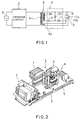
- a power supply unit 1 for a microwave oven comprises a unit of an inverter circuit 3, a unit of a voltage doubler rectifier circuit 4, a step-up transformer 6 and an electronic part 7. These parts are disposed on a substrate 5 mounted on a support frame 2.
- the inverter circuit 3 is connected to a commercial power supply 8.
- an AC output voltage from the commercial power supply 3 is rectified and then, converted to a high frequency voltage, which voltage is supplied to a primary winding 6a of the step-up transformer 6.
- a secondary winding 6b of the step-up transformer 6 is connected between an anode 13a and a cathode 13b or filament through the voltage doubler rectifier circuit 4 comprising a high-voltage capacitor 9 and a high-voltage diode 10.
- the step-up transformer 6 is further provided with a tertiary winding or filament winding 6c magnetically coupled to the secondary winding 6b as well as to the primary winding 6a.
- the tertiary winding 6c is connected between ends of the cathode 13b (filament) of the magnetron 13.
- an iron core 14 of the step-up transformer 6 comprises two generally U-shaped ferrite cores 14a and 14b arranged into an annular shape with a gap 16 therebetween to be opposite to each other.
- the primary winding 6a is wound on one of legs of the iron core 14 so as to extend over both ferrite cores 14a, 14b.
- the secondary winding 6b is wound so as to be concentric with the primary winding 6a.
- the tertiary or filament winding 6c is wound on a leg of the iron core 14 opposed to the leg on which the primary winding 6a is wound.
- a non-magnetic, shape memory plastics 15 serving as a thermally responsive member is disposed in the gap 16 formed between the ferrite cores 14a, 14b.
- a leakage reactance is formed by the gap 16 so that a magnetic field around the iron core 14 is prevented from being saturated for the purpose of improvement of the high frequency characteristics.
- the height of the shape memory plastics 15 disposed in the gap 16 of the iron core 14 and that is, the length of the gap 16 are reduced with increase in the ambient temperature.
- the high frequency voltage from the inverter circuit 3 is applied to the primary winding 6a of the step-up transformer 6 when the power supply is put to work.
- a secondary voltage is then developed in the secondary winding 6b.
- the secondary voltage is applied across the anode 13a and the cathode 13b of the magnetron 13 via the voltage doubler rectifier circuit 4.
- another voltage is developed in the tertiary winding 6c and this voltage is applied as the filament voltage across ends of the cathode or filament 13b of the magnetron 13 such that the filament 13b generates heat. Consequently, since an anode current flows across the anode 13a and the cathode 13b, microwaves are radiated from the magnetron 13.
- the temperature of the shape memory plastics 15 is increased with increase in the ambient temperature due to the heating of the magnetron 13.
- the height of the shape memory plastics 15 in FIG. 3 is reduced with increase in its temperature and accordingly, the length of the gap 16 is reduced in accordance with the characteristic shown in FIG. 4. Consequently, the average magnetic permeability of the iron core 14 of the step-up transformer 6 is increased with reduction in the height of the gap 16, which raises the induced voltage of the filament winding 6c.
- the filament voltage is thus raised as shown in FIG. 5.
- the gap 16 of the iron core 14 is reduced by the shape memory plastics 15 such that the filament voltage is raised.
- the filament voltage can be prevented from dropping.
- FIG. 6 shows the relationship between the filament voltage and the anode temperature of the magnetron 13 or the magnet temperature of the magnetron 13 with lapse of time from the start of drive of the magnetron both in the prior art and in the present invention.
- the increase in the temperature of the magnetron causes the filament voltage to drop below the lower limit operating voltage in the prior art when the temperature of the anode of the magnetron is increased.
- the filament voltage can be effectively prevented from dropping below the lower limit operating voltage in spite of the increase in the temperature of the magnetron.
- shape memory plastics 15 is employed as the thermally responsive member in the foregoing embodiment, a shape memory alloy with a relatively small magnetic permeability may be used instead. Further, one ferrite core 14a may be suspended from a shape memory alloy and the ferrite core 14a may be lowered with increase in the ambient temperature such that the gap 16 is reduced.
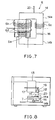
- FIGS. 7 through 9 show a second embodiment of the invention.
- a filament voltage detecting winding 6d is wound on the iron core 14 in the vicinity of the secondary winding 6b for detecting the filament voltage.
- the filament voltage detecting winding 6d delivers a voltage signal in accordance with the magnitude of the detected output voltage of the secondary winding 6b.
- the shape memory plastics disposed in the gap 16 of the step-up transformer 6 in the first embodiment is eliminated in the second embodiment.
- FIG. 8 shows the arrangement of a machine compartment of the microwave oven.
- a stepping motor 18 serving as an actuator is mounted on a waveguide 17 extending from the magnetron 13.
- One of two ends of a timing belt 20 is fixed to a pulley 19 mounted on the stepping motor 18.
- the other end of the timing belt 20 is secured to the upper end of the ferrite core 14a of the step-up transformer 6.
- the ferrite core 14a is suspended with the gap 16 of predetermined dimensions between the ferrite cores 14a and 14b.
- an output of the filament voltage detecting winding 6d is supplied to a control circuit 21 arranged on a printed circuit board. Based on the filament voltage from the filament voltage detecting winding 6d, the control circuit 21 delivers a control signal to a signal circuit 22. Upon receipt of the control signal, the signal circuit 22 drives the stepping motor 18 through a drive circuit 23. In this regard, the control circuit 21 delivers the control signal so that the gap 16 of the iron core 14 is reduced by the stepping motor 18 as the filament voltage drops.
- the stepping motor 18 is driven to lower the ferrite core 14a so that the length of the gap 16 is reduced. Consequently, the filament voltage can be prevented from dropping as in the first embodiment even when the filament voltage tends to drop because of the heating of the magnetron 13.
- a temperature sensor 24 may be provided for sensing the temperature of the magnetron 13 instead of the filament voltage detecting winding 6d.
- the stepping motor 18 may be driven based on a temperature signal generated by the temperature sensor 24.
Landscapes
- Engineering & Computer Science (AREA)
- Power Engineering (AREA)
- Physics & Mathematics (AREA)
- Electromagnetism (AREA)
- Control Of High-Frequency Heating Circuits (AREA)
Claims (4)
- Stromversorgungseinheit für einen Mikrowellenherd, welche mit einem Magnetron (13) für die Erzeugung von Hochfrequenzwellen zum Erhitzen von Nahrungsmitteln versehen ist, wobei die Stromversorgungseinheit ausgestattet ist mit einem Wechselrichter (3) welcher Wechselspannung in Gleichspannung umwandelt und welcher desweiteren die Gleichspannung in eine Hochfrequenzspannung umwandelt, mit einem Aufwärtstransformator (6) der die von dem Wechselrichter (3) gelieferte Hochfrequenzspannung herauftransformiert, wobei der Aufwärtstransformator (6) einen Eisenkern (14) und einen Spalt (16) hat der so ausgelegt ist, daß er sich über einen magnetischen Pfad des Eisenkerns (14) erstreckt, mit einer Gleichrichterschaltung (4) welche eine von dem Aufwärtstransformator (6) gelieferte Wechselspannung in eine Gleichspannung umwandelt, wobei diese Gleichspannung an das Magnetron (13) angelegt wird, gekennzeichnet durch ein Spalteinstellmittel zum Einstellen der Länge des Spaltes (16) mit einer Zunahme der Temperatur desselben in Übereinstimmung mit den Änderungen in einer Umgebungstemperatur, so daß die Länge des Spaltes (16) verkleinert wird.
- Stromversorgungseinheit gemäß Anspruch 1, dadurch gekennzeichnet, daß das Spalteinstellmittel ein thermisch reagierendes Glied (15) aufweist, welches in dem Spalt (16) des Eisenkernes (14) des Aufwärtstransformators (6) angeordnet ist und die Dimensionen desselben in Übereinstimmung mit der Umgebungstemperatur verändert.
- Stromversorgungseinheit gemäß Anspruch 1. dadurch gekennzeichnet, daß der Aufwärtstransformator (6) ausgestattet ist mit einer tertiären Windung (6c). welche eine Spannung abgibt die an die Kathode (13b) des Magnetrons (13) angelegt ist, und daß das Spalteinstellmittel ein Spannungserfassungsmittel (6d) zur Erfassung einer Ausgangsspannung der tertiären Windung (6c) des Aufwärtstransformators (6) aufweist und dadurch ein Erfassungssignal erzeugt, und wobei ein Stellorgan (18) die Länge des Spaltes (16) des Eisenkerns (14) des Aufwärtstransformators (6) in Übereinstimmung mit den Änderungen der Ausgangsspannung der tertiären Windung (6c) als Reaktion auf das Erfassungssignal aus dem Spannungserfassungsmittel (6d) einstellt.
- Stromversorgungseinheit gemäß Anspruch 1, dadurch gekennzeichnet, daß das Spalteinstellmittel ausgestattet ist mit einem Fühler für die Umgebungstemperatur (24) zwecks Erfassung der Umgebungstemperatur, und dadurch ein Temperatursignal erzeugt wird, und mit einem Stellorgan (18) zur Einstellung der Länge des Spaltes (16) des Eisenkerns (14) des Aufwärtstransformators (6) in Übereinstimmung mit den Änderungen der Umgebungstemperatur als Reaktion auf das Temperatursignal aus dem Fühler für die Umgebungstemperatur (24).
Applications Claiming Priority (4)
| Application Number | Priority Date | Filing Date | Title |
|---|---|---|---|
| JP28467991 | 1991-10-30 | ||
| JP284679/91 | 1991-10-30 | ||
| JP325583/91 | 1991-12-10 | ||
| JP3325583A JPH05182755A (ja) | 1991-10-30 | 1991-12-10 | 電子レンジ |
Publications (2)
| Publication Number | Publication Date |
|---|---|
| EP0540246A1 EP0540246A1 (de) | 1993-05-05 |
| EP0540246B1 true EP0540246B1 (de) | 1996-03-20 |
Family
ID=26555564
Family Applications (1)
| Application Number | Title | Priority Date | Filing Date |
|---|---|---|---|
| EP92309650A Expired - Lifetime EP0540246B1 (de) | 1991-10-30 | 1992-10-22 | Stromversorgungseinheit eines Mikrowellenherdes |
Country Status (2)
| Country | Link |
|---|---|
| EP (1) | EP0540246B1 (de) |
| DE (1) | DE69209222D1 (de) |
Families Citing this family (1)
| Publication number | Priority date | Publication date | Assignee | Title |
|---|---|---|---|---|
| KR20260010459A (ko) * | 2023-05-16 | 2026-01-20 | 광동 메이디 키친 어플리언시스 매뉴팩쳐링 코., 엘티디. | 회로기판, 변압기, 마이크로파 발생장치 및 가전기기 |
Family Cites Families (3)
| Publication number | Priority date | Publication date | Assignee | Title |
|---|---|---|---|---|
| SU498607A1 (ru) * | 1974-06-25 | 1976-01-05 | Регул тор температуры | |
| US4835353A (en) * | 1987-12-28 | 1989-05-30 | General Electric Company | Filament power conpensation for magnetron |
| JP2544501B2 (ja) * | 1990-03-30 | 1996-10-16 | シャープ株式会社 | インバ―タ電源搭載電子レンジ |
-
1992
- 1992-10-22 EP EP92309650A patent/EP0540246B1/de not_active Expired - Lifetime
- 1992-10-22 DE DE69209222T patent/DE69209222D1/de not_active Expired - Lifetime
Also Published As
| Publication number | Publication date |
|---|---|
| DE69209222D1 (de) | 1996-04-25 |
| EP0540246A1 (de) | 1993-05-05 |
Similar Documents
| Publication | Publication Date | Title |
|---|---|---|
| US5021620A (en) | High frequency heating apparatus with a temperature compensated switching element | |
| US5274208A (en) | High frequency heating apparatus | |
| EP0489725A2 (de) | Hochfrequenzheizgerät | |
| US5001318A (en) | High frequency heating apparatus with abnormal condition detection | |
| KR920004033B1 (ko) | 전압공진형 스위칭전원장치 | |
| KR910006171B1 (ko) | 고주파 가열장치 | |
| US4962292A (en) | High-frequency heating apparatus having digital controlled inverter | |
| US3784781A (en) | Magnetron moding interrupter control circuit | |
| US5149929A (en) | Microwave oven with inverter controlled power source | |
| EP0540246A1 (de) | Stromversorgungseinheit eines Mikrowellenherdes | |
| EP0851440B1 (de) | Berührungslose Leistungsübertragungsvorrichtung | |
| JPH0567493A (ja) | マイクロ波加熱用電源装置 | |
| KR20200013597A (ko) | 유도 에너지 전송 방법 및 장치 | |
| JP2835975B2 (ja) | 放電灯点灯装置 | |
| KR960014017B1 (ko) | 전자렌지 | |
| JP2692287B2 (ja) | 高周波加熱装置 | |
| JPH01143186A (ja) | 複合調理器 | |
| JP2803284B2 (ja) | 高周波加熱装置 | |
| JP2629247B2 (ja) | 高周波加熱装置 | |
| JP3404894B2 (ja) | 高周波加熱調理器 | |
| JP3183116B2 (ja) | 浴室用電源装置 | |
| JPH0433290A (ja) | マグネトロン駆動装置 | |
| JP2003045637A (ja) | 誘導加熱調理器 | |
| JPH0547467A (ja) | 高周波加熱装置 | |
| JPH07211446A (ja) | 電磁誘導加熱調理器 |
Legal Events
| Date | Code | Title | Description |
|---|---|---|---|
| PUAI | Public reference made under article 153(3) epc to a published international application that has entered the european phase |
Free format text: ORIGINAL CODE: 0009012 |
|
| 17P | Request for examination filed |
Effective date: 19921102 |
|
| AK | Designated contracting states |
Kind code of ref document: A1 Designated state(s): DE FR GB |
|
| 17Q | First examination report despatched |
Effective date: 19950111 |
|
| GRAA | (expected) grant |
Free format text: ORIGINAL CODE: 0009210 |
|
| AK | Designated contracting states |
Kind code of ref document: B1 Designated state(s): DE FR GB |
|
| PG25 | Lapsed in a contracting state [announced via postgrant information from national office to epo] |
Ref country code: FR Effective date: 19960320 |
|
| REF | Corresponds to: |
Ref document number: 69209222 Country of ref document: DE Date of ref document: 19960425 |
|
| PG25 | Lapsed in a contracting state [announced via postgrant information from national office to epo] |
Ref country code: DE Effective date: 19960621 |
|
| GRAH | Despatch of communication of intention to grant a patent |
Free format text: ORIGINAL CODE: EPIDOS IGRA |
|
| EN | Fr: translation not filed | ||
| PLBE | No opposition filed within time limit |
Free format text: ORIGINAL CODE: 0009261 |
|
| 26N | No opposition filed | ||
| PGFP | Annual fee paid to national office [announced via postgrant information from national office to epo] |
Ref country code: GB Payment date: 19971013 Year of fee payment: 6 |
|
| PG25 | Lapsed in a contracting state [announced via postgrant information from national office to epo] |
Ref country code: GB Free format text: LAPSE BECAUSE OF NON-PAYMENT OF DUE FEES Effective date: 19981022 |
|
| GBPC | Gb: european patent ceased through non-payment of renewal fee |
Effective date: 19981022 |