EP0540382A1 - Tôle en acier apte à un emboutissage profond et procédé de fabrication d'une telle tôle - Google Patents
Tôle en acier apte à un emboutissage profond et procédé de fabrication d'une telle tôle Download PDFInfo
- Publication number
- EP0540382A1 EP0540382A1 EP92402748A EP92402748A EP0540382A1 EP 0540382 A1 EP0540382 A1 EP 0540382A1 EP 92402748 A EP92402748 A EP 92402748A EP 92402748 A EP92402748 A EP 92402748A EP 0540382 A1 EP0540382 A1 EP 0540382A1
- Authority
- EP
- European Patent Office
- Prior art keywords
- elements
- welded
- edges
- steel sheet
- laser beam
- Prior art date
- Legal status (The legal status is an assumption and is not a legal conclusion. Google has not performed a legal analysis and makes no representation as to the accuracy of the status listed.)
- Granted
Links
Images


Classifications
-
- B—PERFORMING OPERATIONS; TRANSPORTING
- B23—MACHINE TOOLS; METAL-WORKING NOT OTHERWISE PROVIDED FOR
- B23K—SOLDERING OR UNSOLDERING; WELDING; CLADDING OR PLATING BY SOLDERING OR WELDING; CUTTING BY APPLYING HEAT LOCALLY, e.g. FLAME CUTTING; WORKING BY LASER BEAM
- B23K26/00—Working by laser beam, e.g. welding, cutting or boring
- B23K26/12—Working by laser beam, e.g. welding, cutting or boring in a special environment or atmosphere, e.g. in an enclosure
- B23K26/123—Working by laser beam, e.g. welding, cutting or boring in a special environment or atmosphere, e.g. in an enclosure in an atmosphere of particular gases
-
- B—PERFORMING OPERATIONS; TRANSPORTING
- B23—MACHINE TOOLS; METAL-WORKING NOT OTHERWISE PROVIDED FOR
- B23K—SOLDERING OR UNSOLDERING; WELDING; CLADDING OR PLATING BY SOLDERING OR WELDING; CUTTING BY APPLYING HEAT LOCALLY, e.g. FLAME CUTTING; WORKING BY LASER BEAM
- B23K26/00—Working by laser beam, e.g. welding, cutting or boring
- B23K26/60—Preliminary treatment
-
- C—CHEMISTRY; METALLURGY
- C21—METALLURGY OF IRON
- C21D—MODIFYING THE PHYSICAL STRUCTURE OF FERROUS METALS; GENERAL DEVICES FOR HEAT TREATMENT OF FERROUS OR NON-FERROUS METALS OR ALLOYS; MAKING METAL MALLEABLE, e.g. BY DECARBURISATION OR TEMPERING
- C21D3/00—Diffusion processes for extraction of non-metals; Furnaces therefor
- C21D3/02—Extraction of non-metals
- C21D3/04—Decarburising
-
- B—PERFORMING OPERATIONS; TRANSPORTING
- B23—MACHINE TOOLS; METAL-WORKING NOT OTHERWISE PROVIDED FOR
- B23K—SOLDERING OR UNSOLDERING; WELDING; CLADDING OR PLATING BY SOLDERING OR WELDING; CUTTING BY APPLYING HEAT LOCALLY, e.g. FLAME CUTTING; WORKING BY LASER BEAM
- B23K2103/00—Materials to be soldered, welded or cut
- B23K2103/02—Iron or ferrous alloys
- B23K2103/04—Steel or steel alloys
- B23K2103/05—Stainless steel
-
- C—CHEMISTRY; METALLURGY
- C21—METALLURGY OF IRON
- C21D—MODIFYING THE PHYSICAL STRUCTURE OF FERROUS METALS; GENERAL DEVICES FOR HEAT TREATMENT OF FERROUS OR NON-FERROUS METALS OR ALLOYS; MAKING METAL MALLEABLE, e.g. BY DECARBURISATION OR TEMPERING
- C21D9/00—Heat treatment, e.g. annealing, hardening, quenching or tempering, adapted for particular articles; Furnaces therefor
- C21D9/46—Heat treatment, e.g. annealing, hardening, quenching or tempering, adapted for particular articles; Furnaces therefor for sheet metals
- C21D9/48—Heat treatment, e.g. annealing, hardening, quenching or tempering, adapted for particular articles; Furnaces therefor for sheet metals deep-drawing sheets
Definitions
- the present invention relates to a steel sheet suitable for deep drawing formed of at least two elements welded edge to edge by means of a laser beam.
- the present invention also relates to a method of manufacturing such a steel sheet.
- the focused laser beam necessary for the realization of the welding brings at the level of the joint plane of the two elements, a very important energy which can reach 107 watts per cm2 on a very small zone formed by the point of impact of the beam laser, about 0.2mm.
- This particularly fast thermal cycle causes the metal to quench at the joint plane of the welded area.
- a metallographic analysis of this joint plane after welding using a laser beam reveals the presence of a bainitic structure in the case of low carbon steels (C ⁇ 100 thousandths of a%) and of a martensitic structure in the case steels containing more carbon or a mixed bainito-martensitic structure.
- the joint of the welded zone is harder than the rest of the steel sheet, which causes, during drawing of said sheet, punctual and rapid wear of the drawing die.
- the object of the present invention is to avoid these drawbacks by proposing a steel sheet suitable for deep drawing, produced from at least two elements welded edge to edge by means of a laser beam, the manufacture of which requires no installation. cooling complex.
- the present invention therefore relates to a steel sheet suitable for deep drawing, formed of at least two elements welded edge to edge by means of a laser beam, characterized in that the edges to be welded of said elements are previously decarburized and oxidized by means of a laser beam with oxygen supply.
- the laser beam comes from a laser of the CO2 type.
- decarburization and oxidation of the edges to be welded of the elements are carried out by cutting said elements by means of a laser of the type CO2.
- the sheet according to the invention consisting of at least two butted elements welded edge to edge by means of a laser beam, undergoes a decarburization and oxidation treatment before welding.
- This decarburization and oxidation treatment should only affect the edges to be joined of each element to be joined.
- the laser beam when it is oriented perpendicular to the surface of the edges of the elements to be welded and when swept along this surface, provides a certain amount of energy which allows the metal constituting the edges of the elements to liquefy.
- oxygen reacts with iron ions in the molten area, depending on the reaction: Fe + O2 ⁇ FeO + FeO2 + ... thus creating at the ends of the edges elements of iron oxides.
- the low carbon zone extends approximately 0.1mm to 0.2mm from the free end of the sheet.
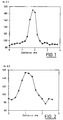
- the maximum hardness of the area affected by the weld is 190 Hv 0.5 to about 1.8 mm from the edge of said area (Fig. 1).
- the maximum hardness is lower with decarburization and prior oxidation of the edges of the elements to be welded.
- the hardness Hv 0.5 without preparation of the edges is at most equal to 330 Hv 0.5 while it does not exceed 280 Hv 0.5 when the edges have been decarburized and oxidized (Figs. 3 and 4 ).
- the hardness Hv 0.5 without preparation of the edges of the elements to be welded is at most equal to 285 Hv 0.5, while it does not exceed 230 Hv 0.5 when the edges have been decarburized and oxidized.
- the present invention also relates to a method of manufacturing a steel sheet suitable for deep drawing and formed of at least two elements welded edge to edge by means of a laser beam.
- decarburization and oxidation of the edges to be welded of the elements are carried out before welding, directly by cutting said elements by means of a CO2 type laser and by supplying oxygen.
- edges of the elements to be welded undergo decarburization and oxidation.
Landscapes
- Engineering & Computer Science (AREA)
- Mechanical Engineering (AREA)
- Chemical & Material Sciences (AREA)
- Physics & Mathematics (AREA)
- Plasma & Fusion (AREA)
- Optics & Photonics (AREA)
- Thermal Sciences (AREA)
- Crystallography & Structural Chemistry (AREA)
- Materials Engineering (AREA)
- Metallurgy (AREA)
- Organic Chemistry (AREA)
- Laser Beam Processing (AREA)
- Blow-Moulding Or Thermoforming Of Plastics Or The Like (AREA)
- Heat Treatment Of Sheet Steel (AREA)
Abstract
Description
- La présente invention concerne une tôle en acier apte à un emboutissage profond formée d'au moins deux éléments soudés bord à bord au moyen d'un faisceau laser.
- La présente invention concerne également un procédé de fabrication d'une telle tôle en acier.
- Il est connu, pour fabriquer des tôles en acier formées d'au moins deux éléments raboutés, à bord de balayer le plan de joint desdits éléments au moyen d'un rayon laser focalisé apportant une énergie suffisante pour réaliser, après passage du faisceau laser, une zone soudée.
- Mais, lorsque l'on réalise des tôles en acier destinées à être ultérieurement profondément embouties, le soudage par un faisceau laser présente un inconvénient majeur.
- En effet, le faisceau laser focalisé nécessaire à la réalisation de la soudure apporte au niveau du plan de joint des deux éléments, une énergie très importante qui peut atteindre 10⁷ watts par cm² sur une zone très petite formée par le point d'impact du faisceau laser, soit environ sur 0,2mm.
- Par conséquent, le cycle thermique subi par le métal au niveau du point d'impact du faisceau laser, est extrèmement rapide aussi bien au cours de la phase de chauffage qu'au cours de la phase de refroidissement.
- Des mesures ont été effectuées, et on constate que le passage d'une température de 500 à 800°C lors du chauffage est inférieure au dixième de seconde et de 800 à 500°C lors du refroidissement ne dépasse pas 2 secondes.
- Ce cycle thermique particulièrement rapide entraîne une trempe du métal au niveau du plan de joint de la zone soudée.
- Une analyse métallographique de ce plan de joint après soudage au moyen d'un faisceau laser révèle la présence d'une structure bainitique dans le cas des aciers à bas carbone (C < 100 milième de %) et d'une structure martensitique dans le cas des aciers contenant plus de carbone ou une structure mixte bainito-martensitique.
- Ainsi, le joint de la zone soudée est plus dur que le reste de la tôle en acier ce qui entraîne, lors d'un emboutissage de ladite tôle, une usure ponctuelle et rapide de la matrice d'emboutissage.
- Dans le cas d'un emboutissage profond, la différence de structure métallographique entre le métal de base de la tôle en acier et de la zone soudée entraîne un coefficient d'amincissement différent et parfois une rupture du joint, celui-ci se déformant moins que le reste de la tôle en acier.
- Des essais ont été effectués sur deux nuances d'acier.
- Sur un acier bas carbone dont la dureté est d'environ 100 Hv 0,5, celle ci passe à 250 Hv 0,5 dans la zone affectée par la soudure.
- Sur un acier micro-allié du type HLE à haute caractéristique mécanique, dont la dureté est d'environ 200 Hv 0,5, celle-ci passe à 450 Hv 0,5 dans la zone affectée par la soudure.
- Il est connu pour améliorer la faculté d'emboutissage d'une tôle en acier réalisée par soudage au moyen d'un faisceau laser d'au moins deux éléments raboutés, de préparer lesdits éléments à souder en respectant une ondulation des bords à rabouter d'au plus 0,04mm et de refroidir les éléments des deux côtés du cordon de soudure sur toute leur longueur pendant leur soudage de manière que la zone affectée par la soudure ne dépasse pas une largeur de 1mm.
- Une telle préparation nécessite un matériel très précis afin de respecter les conditions d'ondulation des bords et une installation complexe pour refroidir les tôles.
- La présente invention a pour but d'éviter ces inconvénients en proposant une tôle en acier apte à un emboutissage profond, réalisée à partir d'au moins deux éléments soudés bord à bord au moyen d'un faisceau laser dont la fabrication ne nécessite aucune installation complexe de refroidissement.
- La présente invention a donc pour objet une tôle en acier apte à un emboutissage profond, formée d'au moins deux éléments soudés bord à bord au moyen d'un faisceau laser, caractérisé en ce que les bords à souder desdits éléments sont préalablement décarburés et oxydés au moyen d'un faisceau laser avec apport d'oxygène.
- Selon une autre caractéristique, le faisceau laser est issu d'un laser du type CO2.
- La présente invention a également pour objet un procédé de fabrication d'une tôle en acier formée d'au moins deux éléments soudés bord à bord au moyen d'un faisceau laser, procédé dans lequel :
- on balaye les bords à souder des éléments avec un faisceau laser et simultanément on apporte de l'oxygène pour réaliser une décarburation et une oxydation desdits bords,
- on joint les bords à souder des éléments,
- et on balaye le plan de joint desdits éléments avec un laser de soudage pour former un joint soudé.
- Selon une autre caractéristique du procédé de l'invention, on effectue avant le soudage, la décarburation et l'oxydation des bords à souder des éléments en découpant lesdits éléments au moyen d'un laser du type CO2.
- Les caractéristiques et avantages de l'invention apparaîtront au cours de la description qui va suivre, donnée uniquement à titre d'exemple, faite en référence aux dessins annexés, sur lesquels :
- la Fig. 1 est une courbe représentant la dureté Hv 0,5 de la zone affectée par la soudure d'une première nuance d'acier, sans décarburation ni oxydation préalables,
- la Fig. 2 est une courbe représentant la dureté Hv 0,5 de la zone affectée par la soudure de la même nuance d'acier, avec décarburation et oxydation préalables,
- les Figs. 3 et 4 sont des courbes représentant la dureté Hv 0,5 de la zone affectée par la soudure d'une seconde nuance d'acier, respectivement sans décarburation ni oxydation préalables et avec décarburation et oxydation préalables,
- les Figs. 5 et 6 sont des courbes représentant la dureté Hv 0,5 de la zone affectée par la soudure d'une troisième nuance d'acier, respectivement sans décarburation ni oxydation préalables et avec décarburation et oxydation préalables.
- La tôle selon l'invention, constituée d'au moins deux éléments raboutés et soudés bord à bord au moyen d'un faisceau laser, subit un traitement de décarburation et d'oxydation avant soudage.
- Ce traitement de décarburation et d'oxydation ne doit affecté que les bords à joindre de chaque élément à rabouter.
- Pour cela, il est avantageux de décarburer les bords des éléments avant soudage au moyen d'un faisceau laser émis par un laser du type CO2 et simultanément d'oxyder lesdits bords par apport d'oxygène.
- En effet, le faisceau laser, lorsqu'il est orienté perpendiculairement à la surface des bords des éléments à souder et lorsqu'il est balayé le long de cette surface, apporte une certaine quantité d'énergie qui permet au métal constitutif des bords des éléments de se liquéfier.
- Pendant l'utilisation du laser pour décarburer, on amène en plus une certaine quantité d'oxygène, laquelle réagit avec le carbone contenu dans le métal des bords des éléments, selon la réaction :

- De plus, l'oxygène réagit avec les ions fer de la zone fondue, selon la réaction:

créant ainsi à l'extrémité des bords des éléments des oxydes de fer. - Lors de la phase ultérieure de soudage, au cours de laquelle on utilise souvent un laser de type CO2 ou Yag les oxydes de fer se décomposent du fait de l'apport important en énergie.
- Par exemple, pour l'oxyde de fer 2, on obtient la réaction :

- L'oxygène dégagé lors de cette réaction réagit encore avec le carbone des bords des éléments pour former du CO.
- Ainsi, la teneur en carbone des extrémités des bords des éléments à souder est diminuée par rapport à la teneur en carbone du reste des éléments. La zone à faible carbone s'étend environ sur 0,1mm à 0,2mm par rapport à l'extrémité libre de la tôle.
- Comme on le voit sur les figures 1 et 2, des essais de dureté ont été réalisés sur une tôle d'acier ES nue et d'épaisseur environ égale à 1,5mm, dont la composition en milième de % est la suivante :
- -carbone
- 3,8
- -manganèse
- 140
- -silicium
- 12
- -aluminium
- 34
- -nickel
- 21
- -chrome
- 16
- On constate que sans préparation préalable des bords des éléments à souder, la dureté maximale de la zone affectée par la soudure est de 190 Hv 0,5 à environ 1,8mm du bord de ladite zone (Fig. 1).
- Avec une décarburation et une oxydation préalables des bords au moyen d'un laser du type CO2 avec apport d'oxygène, cette dureté maximale n'est que de 155 Hv 0,5 à environ 1mm du bord de la zone affectée par la soudure.
- Ainsi, la dureté maximale est moindre avec une décarburation et une oxydation préalables des bords des éléments à souder.
- Les mêmes essais ont été effectués sur une tôle d'acier 3C galvanisée double face d'épaisseur de 2mm dont la composition en milième de % est la suivante :
- -carbone
- 61
- -manganèse
- 427
- -silicium
- 21
- -aluminium
- 52
- -nickel
- 18
- -chrome
- 15
- Dans ce cas, la dureté Hv 0,5 sans préparation des bords est au maximum égale à 330 Hv 0,5 alors qu'elle ne dépasse pas 280 Hv 0,5 lorsque les bords ont été décarburés et oxydés (Figs. 3 et 4).
- Enfin pour une tôle en acier ALUSI BX aluminée double face d'épaisseur de 1,5mm, dont la composition en milième de % est la suivante :
- -manganèse
- 245
- -silicium
- 10
- -aluminium
- 40
- -nickel
- 30
- -chrome
- 20
- le reste étant du fer
on constate que la dureté Hv 0,5 sans préparation des bords des éléments à souder est au maximum égale à 285 Hv 0,5, alors qu'elle ne dépasse pas 230 Hv 0,5 lorsque les bords ont été décarburés et oxydés. - La présente invention concerne également un procédé de fabrication d'une tôle en acier apte à un emboutissage profond et formée d'au moins deux éléments soudés bord à bord au moyen d'un faisceau laser.
- Dans ce procédé :
- on balaye les bords à souder des éléments avec un faisceau laser et simultanément on apporte de l'oxygène pour réaliser une décarburation et une oxydation desdits bords,
- on joint les bords à souder des éléments,
- et on balaye le plan de joint desdits éléments avec un laser de soudage pour former un joint soudé.
- Avantageusement, on effectue avant le soudage, la décarburation et l'oxydation des bords à souder des éléments directement en découpant lesdits éléments au moyen d'un laser du type CO2 et en apportant de l'oxygène.
- Ainsi, pendant l'opération deO découpage des bords des éléments à souder, lesdits bords subissent une décarburation et une oxydation.
le reste étant du fer.
le reste étant du fer.
Claims (4)
- Tôle en acier apte à un emboutissage profond, formée d'au moins deux éléments soudés bord à bord au moyen d'un faisceau laser, caractérisée en ce que les bords à souder desdits éléments sont préalablement décarburés et oxydés au moyen d'un faisceau laser avec apport d'oxygène.
- Tôle en acier selon la revendication 1, caractérisée en ce que le faisceau laser est issu d'un laser du type CO2.
- Procédé de fabrication d'une tôle en acier selon les revendications 1 et 2, caractérisé en ce que:- on balaye les bords à souder des éléments avec un faisceau laser et simultanément on apporte de l'oxygène pour réaliser une décarburation et une oxydation desdits bords,- on joint les bords à souder des éléments,- et on balaye le plan de joint desdits éléments avec un laser de soudage pour former un joint soudé.
- Procédé selon la revendication 3, caractérisé en ce que l'on effectue, avant le soudage, la décarburation et l'oxydation des bords à souder des éléments en découpant lesdits éléments au moyen d'un laser du type CO2 et en apportant de l'oxygène.
Applications Claiming Priority (2)
| Application Number | Priority Date | Filing Date | Title |
|---|---|---|---|
| FR9113505A FR2683174B1 (fr) | 1991-10-31 | 1991-10-31 | Tole en acier apte a un emboutissage profond et procede de fabrication d'une telle tole. |
| FR9113505 | 1991-10-31 |
Publications (2)
| Publication Number | Publication Date |
|---|---|
| EP0540382A1 true EP0540382A1 (fr) | 1993-05-05 |
| EP0540382B1 EP0540382B1 (fr) | 1995-04-12 |
Family
ID=9418539
Family Applications (1)
| Application Number | Title | Priority Date | Filing Date |
|---|---|---|---|
| EP92402748A Expired - Lifetime EP0540382B1 (fr) | 1991-10-31 | 1992-10-08 | Tôle en acier apte à un emboutissage profond et procédé de fabrication d'une telle tôle |
Country Status (5)
| Country | Link |
|---|---|
| EP (1) | EP0540382B1 (fr) |
| AT (1) | ATE120993T1 (fr) |
| DE (1) | DE69202035T2 (fr) |
| ES (1) | ES2071460T3 (fr) |
| FR (1) | FR2683174B1 (fr) |
Cited By (3)
| Publication number | Priority date | Publication date | Assignee | Title |
|---|---|---|---|---|
| WO1996034719A1 (fr) * | 1995-05-05 | 1996-11-07 | Cogifer - Compagnie Generale D'installation Ferroviaires | Soudure sans apport de metal d'un acier au carbone avec un acier fortement allie |
| CN105899320A (zh) * | 2014-01-20 | 2016-08-24 | 通用汽车环球科技运作有限责任公司 | 焊接方法和系统 |
| CN112743235A (zh) * | 2020-12-28 | 2021-05-04 | 长春理工大学 | 一种球墨铸铁与低碳钢的激光焊接方法 |
Family Cites Families (2)
| Publication number | Priority date | Publication date | Assignee | Title |
|---|---|---|---|---|
| JPS5893592A (ja) * | 1981-11-27 | 1983-06-03 | Mitsubishi Heavy Ind Ltd | レ−ザ溶接方法 |
| JPH06104278B2 (ja) * | 1988-02-23 | 1994-12-21 | 三菱電機株式会社 | 非鉄金属の連続処理ラインにおける溶接方法 |
-
1991
- 1991-10-31 FR FR9113505A patent/FR2683174B1/fr not_active Expired - Fee Related
-
1992
- 1992-10-08 EP EP92402748A patent/EP0540382B1/fr not_active Expired - Lifetime
- 1992-10-08 AT AT92402748T patent/ATE120993T1/de not_active IP Right Cessation
- 1992-10-08 DE DE69202035T patent/DE69202035T2/de not_active Expired - Fee Related
- 1992-10-08 ES ES92402748T patent/ES2071460T3/es not_active Expired - Lifetime
Non-Patent Citations (2)
| Title |
|---|
| PATENT ABSTRACTS OF JAPAN vol. 007, no. 193 (M-238)24 Août 1983 & JP-A-58 093 592 ( MITSUBISHI JUKOGYO KK ) 3 Juin 1983 * |
| PATENT ABSTRACTS OF JAPAN vol. 013, no. 526 (M-897)22 Novembre 1989 & JP-A-01 215 484 ( MITSUBISHI ELECTRIC CO. ) 29 Août 1989 * |
Cited By (4)
| Publication number | Priority date | Publication date | Assignee | Title |
|---|---|---|---|---|
| WO1996034719A1 (fr) * | 1995-05-05 | 1996-11-07 | Cogifer - Compagnie Generale D'installation Ferroviaires | Soudure sans apport de metal d'un acier au carbone avec un acier fortement allie |
| FR2733706A1 (fr) * | 1995-05-05 | 1996-11-08 | Cogifer | Soudure sans apport de metal d'un acier au carbone avec un acier allie, procedes d'obtention et application aux appareils de voies ferroviaires |
| CN105899320A (zh) * | 2014-01-20 | 2016-08-24 | 通用汽车环球科技运作有限责任公司 | 焊接方法和系统 |
| CN112743235A (zh) * | 2020-12-28 | 2021-05-04 | 长春理工大学 | 一种球墨铸铁与低碳钢的激光焊接方法 |
Also Published As
| Publication number | Publication date |
|---|---|
| EP0540382B1 (fr) | 1995-04-12 |
| ATE120993T1 (de) | 1995-04-15 |
| FR2683174B1 (fr) | 1995-09-01 |
| DE69202035T2 (de) | 1995-08-24 |
| DE69202035D1 (de) | 1995-05-18 |
| FR2683174A1 (fr) | 1993-05-07 |
| ES2071460T3 (es) | 1995-06-16 |
Similar Documents
| Publication | Publication Date | Title |
|---|---|---|
| US8993920B2 (en) | Method for producing a steel pipe using a high energy density beam | |
| US4471204A (en) | Method for joining of articles by energy beam and apparatus for controlling said method | |
| US7588837B2 (en) | Welding together low and high carbon steels | |
| KR960037157A (ko) | 고밀도 에너지빔의 사용에 의한 강관의 제조방법 | |
| JPH0596392A (ja) | 亜鉛メツキ鋼のレーザー溶接法 | |
| CN101073857A (zh) | 铜或铝与碳钢激光对接焊接方法 | |
| WO2003018976A1 (fr) | Procede permettant de fermer un orifice de travail dans la partie superieure d'une ailette de turbine a gaz | |
| US4560855A (en) | Method for joining of articles by energy beam and apparatus for controlling said method | |
| CN102652046A (zh) | 焊接方法和焊接装置 | |
| EP0540382B1 (fr) | Tôle en acier apte à un emboutissage profond et procédé de fabrication d'une telle tôle | |
| JP4066433B2 (ja) | レーザ照射による異種材料の接合方法と装置 | |
| US20080206586A1 (en) | Penetration welding method of t-type joint and penetration welding structure of t-type joint | |
| JPH09220682A (ja) | 2相ステンレス溶接鋼管の製造方法 | |
| JP2002336983A (ja) | 異種金属の接合方法 | |
| JPH10225782A (ja) | レーザとアークによる複合溶接方法 | |
| JP3134706B2 (ja) | 溶接鋼管の製造方法 | |
| WO1996034719A1 (fr) | Soudure sans apport de metal d'un acier au carbone avec un acier fortement allie | |
| JPS6120688A (ja) | 銅または銅合金の熔接方法 | |
| JPH0341272B2 (fr) | ||
| JPH01148760A (ja) | セラミックスの接合方法 | |
| JP2792340B2 (ja) | レーザ溶接方法 | |
| JPH01205893A (ja) | 高炭素鋼板の溶接方法 | |
| JPH1058029A (ja) | 溶接鋼管の製造方法 | |
| JPH0569178A (ja) | 突合わせ溶接機の後加熱装置及び誘導加熱コイル装置 | |
| JPS6096382A (ja) | レ−ザによる極薄鋼板の溶接方法 |
Legal Events
| Date | Code | Title | Description |
|---|---|---|---|
| PUAI | Public reference made under article 153(3) epc to a published international application that has entered the european phase |
Free format text: ORIGINAL CODE: 0009012 |
|
| 17P | Request for examination filed |
Effective date: 19921212 |
|
| AK | Designated contracting states |
Kind code of ref document: A1 Designated state(s): AT BE CH DE DK ES FR GB GR IT LI LU NL PT SE |
|
| 17Q | First examination report despatched |
Effective date: 19940614 |
|
| GRAA | (expected) grant |
Free format text: ORIGINAL CODE: 0009210 |
|
| AK | Designated contracting states |
Kind code of ref document: B1 Designated state(s): AT BE CH DE DK ES FR GB GR IT LI LU NL PT SE |
|
| PG25 | Lapsed in a contracting state [announced via postgrant information from national office to epo] |
Ref country code: GR Free format text: LAPSE BECAUSE OF FAILURE TO SUBMIT A TRANSLATION OF THE DESCRIPTION OR TO PAY THE FEE WITHIN THE PRESCRIBED TIME-LIMIT Effective date: 19950412 Ref country code: DK Effective date: 19950412 |
|
| REF | Corresponds to: |
Ref document number: 120993 Country of ref document: AT Date of ref document: 19950415 Kind code of ref document: T |
|
| REF | Corresponds to: |
Ref document number: 69202035 Country of ref document: DE Date of ref document: 19950518 |
|
| ITF | It: translation for a ep patent filed | ||
| REG | Reference to a national code |
Ref country code: ES Ref legal event code: FG2A Ref document number: 2071460 Country of ref document: ES Kind code of ref document: T3 |
|
| GBT | Gb: translation of ep patent filed (gb section 77(6)(a)/1977) |
Effective date: 19950712 |
|
| SC4A | Pt: translation is available |
Free format text: 950616 AVAILABILITY OF NATIONAL TRANSLATION |
|
| PG25 | Lapsed in a contracting state [announced via postgrant information from national office to epo] |
Ref country code: LI Effective date: 19951031 Ref country code: CH Effective date: 19951031 |
|
| PLBE | No opposition filed within time limit |
Free format text: ORIGINAL CODE: 0009261 |
|
| STAA | Information on the status of an ep patent application or granted ep patent |
Free format text: STATUS: NO OPPOSITION FILED WITHIN TIME LIMIT |
|
| 26N | No opposition filed | ||
| REG | Reference to a national code |
Ref country code: CH Ref legal event code: PL |
|
| REG | Reference to a national code |
Ref country code: GB Ref legal event code: IF02 |
|
| PGFP | Annual fee paid to national office [announced via postgrant information from national office to epo] |
Ref country code: SE Payment date: 20020917 Year of fee payment: 11 Ref country code: LU Payment date: 20020917 Year of fee payment: 11 |
|
| PGFP | Annual fee paid to national office [announced via postgrant information from national office to epo] |
Ref country code: AT Payment date: 20020918 Year of fee payment: 11 |
|
| PGFP | Annual fee paid to national office [announced via postgrant information from national office to epo] |
Ref country code: NL Payment date: 20020919 Year of fee payment: 11 |
|
| PGFP | Annual fee paid to national office [announced via postgrant information from national office to epo] |
Ref country code: GB Payment date: 20021001 Year of fee payment: 11 |
|
| PGFP | Annual fee paid to national office [announced via postgrant information from national office to epo] |
Ref country code: DE Payment date: 20021007 Year of fee payment: 11 |
|
| PGFP | Annual fee paid to national office [announced via postgrant information from national office to epo] |
Ref country code: PT Payment date: 20021009 Year of fee payment: 11 |
|
| PGFP | Annual fee paid to national office [announced via postgrant information from national office to epo] |
Ref country code: ES Payment date: 20021011 Year of fee payment: 11 |
|
| PGFP | Annual fee paid to national office [announced via postgrant information from national office to epo] |
Ref country code: FR Payment date: 20021015 Year of fee payment: 11 |
|
| PGFP | Annual fee paid to national office [announced via postgrant information from national office to epo] |
Ref country code: BE Payment date: 20021118 Year of fee payment: 11 |
|
| PG25 | Lapsed in a contracting state [announced via postgrant information from national office to epo] |
Ref country code: LU Free format text: LAPSE BECAUSE OF NON-PAYMENT OF DUE FEES Effective date: 20031008 Ref country code: GB Free format text: LAPSE BECAUSE OF NON-PAYMENT OF DUE FEES Effective date: 20031008 Ref country code: AT Free format text: LAPSE BECAUSE OF NON-PAYMENT OF DUE FEES Effective date: 20031008 |
|
| PG25 | Lapsed in a contracting state [announced via postgrant information from national office to epo] |
Ref country code: SE Free format text: LAPSE BECAUSE OF NON-PAYMENT OF DUE FEES Effective date: 20031009 Ref country code: ES Free format text: LAPSE BECAUSE OF NON-PAYMENT OF DUE FEES Effective date: 20031009 |
|
| PG25 | Lapsed in a contracting state [announced via postgrant information from national office to epo] |
Ref country code: BE Free format text: LAPSE BECAUSE OF NON-PAYMENT OF DUE FEES Effective date: 20031031 |
|
| BERE | Be: lapsed |
Owner name: *SOLLAC Effective date: 20031031 |
|
| PG25 | Lapsed in a contracting state [announced via postgrant information from national office to epo] |
Ref country code: PT Free format text: LAPSE BECAUSE OF NON-PAYMENT OF DUE FEES Effective date: 20040430 |
|
| PG25 | Lapsed in a contracting state [announced via postgrant information from national office to epo] |
Ref country code: NL Free format text: LAPSE BECAUSE OF NON-PAYMENT OF DUE FEES Effective date: 20040501 Ref country code: DE Free format text: LAPSE BECAUSE OF NON-PAYMENT OF DUE FEES Effective date: 20040501 |
|
| GBPC | Gb: european patent ceased through non-payment of renewal fee |
Effective date: 20031008 |
|
| EUG | Se: european patent has lapsed | ||
| PG25 | Lapsed in a contracting state [announced via postgrant information from national office to epo] |
Ref country code: FR Free format text: LAPSE BECAUSE OF NON-PAYMENT OF DUE FEES Effective date: 20040630 |
|
| NLV4 | Nl: lapsed or anulled due to non-payment of the annual fee |
Effective date: 20040501 |
|
| REG | Reference to a national code |
Ref country code: FR Ref legal event code: ST Ref country code: PT Ref legal event code: MM4A Free format text: LAPSE DUE TO NON-PAYMENT OF FEES Effective date: 20040430 |
|
| REG | Reference to a national code |
Ref country code: ES Ref legal event code: FD2A Effective date: 20031009 |
|
| PG25 | Lapsed in a contracting state [announced via postgrant information from national office to epo] |
Ref country code: IT Free format text: LAPSE BECAUSE OF NON-PAYMENT OF DUE FEES;WARNING: LAPSES OF ITALIAN PATENTS WITH EFFECTIVE DATE BEFORE 2007 MAY HAVE OCCURRED AT ANY TIME BEFORE 2007. THE CORRECT EFFECTIVE DATE MAY BE DIFFERENT FROM THE ONE RECORDED. Effective date: 20051008 |