EP0540634B1 - Appareil de commande automatique de processus industriels avec circuit de protection contre les surintensites provenant d'une boucle de courant - Google Patents
Appareil de commande automatique de processus industriels avec circuit de protection contre les surintensites provenant d'une boucle de courant Download PDFInfo
- Publication number
- EP0540634B1 EP0540634B1 EP91913991A EP91913991A EP0540634B1 EP 0540634 B1 EP0540634 B1 EP 0540634B1 EP 91913991 A EP91913991 A EP 91913991A EP 91913991 A EP91913991 A EP 91913991A EP 0540634 B1 EP0540634 B1 EP 0540634B1
- Authority
- EP
- European Patent Office
- Prior art keywords
- current
- loop
- process control
- impedance
- instrument
- Prior art date
- Legal status (The legal status is an assumption and is not a legal conclusion. Google has not performed a legal analysis and makes no representation as to the accuracy of the status listed.)
- Expired - Lifetime
Links
- 238000004886 process control Methods 0.000 title claims abstract description 64
- 230000002441 reversible effect Effects 0.000 claims abstract description 29
- 230000000670 limiting effect Effects 0.000 claims description 9
- 238000000034 method Methods 0.000 claims description 9
- 230000005669 field effect Effects 0.000 claims description 6
- 230000008878 coupling Effects 0.000 claims description 4
- 238000010168 coupling process Methods 0.000 claims description 4
- 238000005859 coupling reaction Methods 0.000 claims description 4
- 230000002401 inhibitory effect Effects 0.000 claims description 2
- 230000015556 catabolic process Effects 0.000 abstract description 5
- 238000006731 degradation reaction Methods 0.000 abstract description 5
- 230000000694 effects Effects 0.000 abstract description 2
- 230000002829 reductive effect Effects 0.000 description 13
- 230000001965 increasing effect Effects 0.000 description 7
- 238000004519 manufacturing process Methods 0.000 description 4
- 239000004020 conductor Substances 0.000 description 3
- 238000010586 diagram Methods 0.000 description 3
- 230000001681 protective effect Effects 0.000 description 2
- 238000012369 In process control Methods 0.000 description 1
- 239000003990 capacitor Substances 0.000 description 1
- 230000003247 decreasing effect Effects 0.000 description 1
- 238000007599 discharging Methods 0.000 description 1
- 238000004146 energy storage Methods 0.000 description 1
- 239000002360 explosive Substances 0.000 description 1
- 238000010965 in-process control Methods 0.000 description 1
- 230000001939 inductive effect Effects 0.000 description 1
- 230000000630 rising effect Effects 0.000 description 1
Images

Classifications
-
- H—ELECTRICITY
- H02—GENERATION; CONVERSION OR DISTRIBUTION OF ELECTRIC POWER
- H02H—EMERGENCY PROTECTIVE CIRCUIT ARRANGEMENTS
- H02H11/00—Emergency protective circuit arrangements for preventing the switching-on in case an undesired electric working condition might result
- H02H11/002—Emergency protective circuit arrangements for preventing the switching-on in case an undesired electric working condition might result in case of inverted polarity or connection; with switching for obtaining correct connection
-
- H—ELECTRICITY
- H02—GENERATION; CONVERSION OR DISTRIBUTION OF ELECTRIC POWER
- H02H—EMERGENCY PROTECTIVE CIRCUIT ARRANGEMENTS
- H02H9/00—Emergency protective circuit arrangements for limiting excess current or voltage without disconnection
- H02H9/02—Emergency protective circuit arrangements for limiting excess current or voltage without disconnection responsive to excess current
- H02H9/025—Current limitation using field effect transistors
-
- H—ELECTRICITY
- H02—GENERATION; CONVERSION OR DISTRIBUTION OF ELECTRIC POWER
- H02H—EMERGENCY PROTECTIVE CIRCUIT ARRANGEMENTS
- H02H9/00—Emergency protective circuit arrangements for limiting excess current or voltage without disconnection
- H02H9/008—Intrinsically safe circuits
Definitions
- This invention relates to industrial process control instruments such as pressure transmitters, current to pressure (I/P) converters, and the like having overcurrent and reverse current protection circuits.
- industrial process control instruments such as pressure transmitters, current to pressure (I/P) converters, and the like having overcurrent and reverse current protection circuits.
- overcurrent and reverse current protection circuits operate between a two-wire DC current loop and a process control instrument. These protection circuits reduce the incidence of damage or degradation to the process control instrument from excessive and reverse polarity currents from the loop.
- process control instruments include pressure, temperature, flow, pH, conductivity and the like transmitters, are shown for example in US-A 3975719, and current to pressure converters, valve actuators and the like, are shown for example in US-A 4481967.
- Some instruments include a diode in series with the two wire loop to block the flow of reverse current, as taught in US-A 3975719 and US-A 4783659 for two wire transmitters.
- the diode produces a large potential drop in the instrument when current flows in the proper direction, which significantly increases the lift-off voltage and reduces the permissible wire length.
- US-A 3975719 and US-A 4783659 also teach overcurrent protection circuits in two wire current transmitters. These Patents teach a resistor in series with the two wire loop and connected to the emitter of a transistor with one end of a Zener diode connected to a remote end of the resistor and the other end of the Zener diode connected to the base of the transistor. While this combination limits the maximum value of the loop current, a large potential drop is produced across the resistor during normal operation which further contributes to increasing the lift-off potential of the process control instrument.
- US-A-3571608 discloses a protective circuit for use with a transmitter.
- the protective circuit includes a transistor arranged such that current flowing through the protected device also flows through the transistor.
- the current flow through the transistor and hence the protected device is kept from rising above a predetermined value by means of voltage-sensitive devices, such as diodes, which clamp the voltage drop across a resistor through which the current flows.
- the output voltage is also clamped substantially to zero, upon reversal of the input voltage polarity, by a voltage-sensitive device, such as a diode, connected between the transistor base and the opposite input terminal.
- DE-C-3804250 discloses a circuit for limiting current flow through digital telephone receivers powered by a supply voltage via the two leads of the subscriber's line.
- Current flowing through a telephone receiver also flows through a first resistor, a self-locking field-effect transistor and a Zener diode.
- the first resistor is connected across the collector and base of a transistor. If the current flowing through the first resistor exceeds a permitted maximum, the transistor is switched into the conducting state via its base and a current is conducted via the emitter and collector of the transistor and through a second resistor which has a high impedance as compared with the first resistor.
- the gate of the field-effect transistor is connected between the transistor and the second resistor, the effect of current flowing through the transistor is to raise the gate potential and thereby limit the current flowing through the field-effect transistor and hence through the telephone receiver.
- the circuit includes a MOSFET and a resistor connected across the electronic unit such that current flowing through the electronic unit flows through the source and drain of the MOSFET.
- the MOSFET When voltage of the correct polarity is applied to the electronic unit, the MOSFET is conductive. If the polarity of the supply voltage is reversed, the MOSFET is inherently turned off and no current flows.
- a process control instrument comprising:
- a process control instrument includes overcurrent and preferably reverse current protection circuits, having reduced potential drops and reduced leakage currents, to reduce incidence of damage or degradation to a process control instrument, such as a pressure, temperature, flow, pH, or conductivity transmitter; or a current to pressure (I/P) converter, a valve actuator, or the like.
- a process control instrument such as a pressure, temperature, flow, pH, or conductivity transmitter; or a current to pressure (I/P) converter, a valve actuator, or the like.
- I/P current to pressure
- the reverse current protection circuit conducts the device current between the loop and the process control device and responds to the loop potential.
- the circuit has second impedance means having a second variable impedance for inhibiting the device current from flowing through the device when the loop potential is reversed from a predetermined polarity.
- the circuit diverts substantially no device current back to the loop when loop potential comprises a proper polarity and loop current is within the predetermined normal range.
- Instrument 10 is wired in series with power source 44 and a separate process control device 42 to form two-wire loop 11 carrying a DC loop current.
- loop current or voltage in such instruments can exceed a predetermined normal range, e.g. 0-60 mA for a 4-20 mA loop where 60 mA is an upper limit, which would damage or degrade performance of process control device 24, such as a pressure transmitter.
- instrument 10 includes protection circuit 17 coupling current from loop 11 to device 24.
- Protection circuit 17 receives DC loop current I 1 +I 2 and passes only normal current or device current I 1 of the loop current on to device 24. Circuit 17 limits device current I 1 to a level in the normal range which prevents or reduces degradation of device 24. The remainder of the loop current, shunt current or overcurrent I 2 , is shunted back to loop 11 for controlling the level of device current I 1 . Shunt current I 2 is substantially zero until amplitude of normal current I 1 attains the upper limit in the normal range.
- Process control device 24 such as a pressure transmitter as disclosed, senses process variable "PV" as illustrated in FIG. 1.
- Process control device 24 controls amplitude of variable normal current I 1 as a function of amplitude of process variable PV and process control device 42 functions as a current sensing instrument, such as a recorder, by sensing amplitude of loop current I 1 +I 2 , and correlating loop current amplitude to the process variable PV.
- process control device 24 can be an output device, such as a current-to-pressure(I/P) converter or a current-to-position converter.
- the separate process current control device 42 such as a controller, controls amplitude of loop current I 1 +I 2
- process control device 24 controls the magnitude of its output, process variable PV, as a function of amplitude of variable normal current I 1 .
- the process control device 24 can also include a circuit for generating and receiving a time-varying-signal sent over loop 11 such as taught in US-A 4665938 to Brown et al.
- the present invention is suitable for use in a process control system utilizing multidrop process instruments, such as pressure transmitters, each connected in parallel across a two wire loop and processing information by superimposing digital data over a DC line.
- multidrop process instruments such as pressure transmitters
- Loop 11 provides loop current I 1 +I 2 to terminal 12 in instrument 10, which returns loop current to loop 11 from terminal 40 in instrument 10.
- overcurrent protection circuit 16 and reverse current protection circuit 20 isolate process control device 24 from excessive currents from the loop 11.
- Loop current I 1 +I 2 flows from terminal 12 to node A in overcurrent protection circuit 16.
- any overcurrent I 2 flows to current sensing means 13, while normal current I 1 flows to node B in reverse current protection circuit 20, as will be explained later.
- normal current I 1 flows on to terminal 22 of process control device 24. Normal current I 1 flows through process control device 24 back through terminal 26 of process control device 24 to conductor 31.
- Normal current I 1 flows from conductor 31 through reverse current protection circuit 20 to conductor 33 and on through overcurrent protection circuit 16 to node C of overcurrent protection circuit 16.
- overcurrent I 2 from current diverting means 38 is summed with normal current I 1 such that the entire loop current I 1 +I 2 flows from node C out through terminal 40 back to loop 11.
- Normal current I 1 flowing through process control device 24 induces potential V 2 across terminals 22 and 26.
- Potential V 2 is representative of polarity of loop current I 1 +I 2 .
- Potential sense means 18 coupled across a portion of loop 11 senses potential V 2 and generates output 3 indicative of potential V 2 .
- Potential sense means 18 diverts substantially no device current I 1 back to loop 11 when loop potential V 2 is a proper polarity.
- impedance of variable impedance 30 is reduced in response to output 3 and normal current I 1 flows freely through process control device 24 and through variable impedance means 30 to overcurrent protection circuit 16.
- variable impedance 30 When, instead, potential sense means 18 senses potential V 2 as reversed from the proper polarity or insufficient in magnitude, then impedance of variable impedance 30 is increased in response to output 3 thus reducing normal current I 1 flowing through process control device 24 and variable impedance means 30.
- reverse current protection circuit 20 having variable impedance 30 conducting device current I 1 , is responsive to output 3 which is a function of a loop potential V 2 , the protection circuit 20 diverting substantially no device current I 1 back to loop 11 when loop potential V 2 is the proper polarity.
- Amplitude of normal current I 1 flowing through current sense means 34 controls the level of output 1.
- the variable impedance of current diverting means 38 is responsive to the level of output 1. When normal current I 1 flows at the predetermined upper level, output 1 reaches a level such that the impedance of current diverting means 38 is reduced so that shunt current I 2 now flows through current diverting means 38 and also through current sense means 13, which is in series with current diverting means 38.
- the amplitude of shunt current I 2 flowing through current sense means 13 controls the level of output 2.
- the level of output 2, which is indicative of shunt current I 2 controls the impedance of variable impedance 32.
- the impedance of variable impedance 32 controls the amplitude of normal current I 1 flowing from loop 11 in series through process control device 24 and variable impedance 32 such that normal current I 1 does not exceed the predetermined normal range.
- overcurrent protection circuit 16 which senses the magnitude of device current I 1 , prevents device current I 1 from exceeding a predetermined upper limit which can damage or degrade the performance of process control device 24 even when loop current exceeds the predetermined upper limit. Further, the circuit induces a reduced potential drop in the two wire loop. Moreover, the circuit is relatively insensitive to the impedance of the additional device 42.
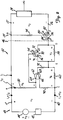
- FIG. 2 shows a schematic diagram of an embodiment of two-wire process control instrument 46 wired in series with power source 44 and process control device 42 to form two-wire loop 43 carrying a DC loop current.
- Instrument 46 comprises overcurrent protection circuit 52, reverse current protection circuit 54 and process control device 24 where the two circuits are interposed between the loop 43 and the process control device 24.
- Overcurrent protection circuit 52 passes only normal current or device current I 1 of loop current through reverse current protection circuit 54 to process control device 24. The remainder of the loop current, shunt current or overcurrent I 2 , is shunted by overcurrent protection circuit 52 back to loop 43.
- Overcurrent I 2 as described later, generates an output which controls the impedance between nodes D and E to maintain the level of normal current I 1 , which flows between nodes D and E, in the normal range.
- Overcurrent I 2 is substantially zero until device current I 1 attains the predetermined upper limit.
- Two-wire loop 43 provides varying DC loop current I 1 +1 2 to terminal 12 of overcurrent protection circuit 52.
- Loop current I 1 +I 2 flows from terminal 12 to node A.
- shunt current I 2 flows to resistor 50, while normal current I 1 flows to node B in reverse current protection circuit 54.
- normal current I 1 is passed on to terminal 22 of process control device 24.
- Normal current I 1 flows through process control device 24 to terminal 26 of process controlling device 24 and on to node D.
- Normal current I 1 flows from node D through node E to node C in overcurrent protection circuit 52.
- shunt current I 2 from transistor 62 is summed with normal current I 1 such that the entire loop current I 1 +I 2 flows from node C out through terminal 40 of process control instrument 46 back to loop 43.
- Normal current I 1 flowing through process control device 24 induces potential V 2 across terminals 22 and 26.
- Potential V 2 is representative of polarity of loop current I 1 +I 2 .
- Enhancement type field-effect transistor (FET) 56 coupled across terminals 22 and 26 senses polarity of potential V 2 via resistor 94 across gate 80 and source 82. Substantially no device current is diverted back to loop 43 from gate 80 to source 82, unlike the leakage from a base to an emitter if a bipolar transistor were substituted for FET 56. Leakage current reduces the accuracy of process control instruments and is undesirable.
- FET 56 When loop current I 1 +I 2 is reversed from the correct polarity such that damage to process control device 24 could occur, FET 56 operates in a depletion mode and is turned off, such that impedance from source 82 to drain 84 is increased thus substantially reducing normal current I 1 flowing through process control device 24.
- Reverse current protection circuit 54 operates independently from overcurrent protection circuit 52 and can be interposed between loop 43 and overcurrent protection circuit 52 and conducting the loop current I 1 +I 2 . It can also be interposed between loop 43 and process control device 24 when overcurrent protection circuit 52 is omitted thus conducting device current I 1 which here is the same as the loop current.
- Normal current I 1 flowing from node E to node C through current sensing resistor 60 induces potential V 4 which is indicative of the amplitude of normal current I 1 .
- potential V 4 across base 68 to emitter 66 biases current diverting means bipolar transistor 62 on, which can also be a FET or the like. Biasing transistor 62 on allows shunt current I 2 to flow from node A through current sensing resistor 50, transistor 62 via collector 64 to emitter 66, and resistor 90 to node C.
- Shunt current I 2 induces potential V 5 across resistor 50 which is indicative of the amplitude of shunt current I 2 .
- Resistor 50 can also comprise other current sensing means that generates a potential corresponding a current, such as a transistor.
- FET 70 When FET 70 operates in the depletion mode, impedance from drain 72 to source 76 is substantially increased and substantially all normal current I 1 flows from node D to node E through current limiting resistor 58 instead of through FET 70 via the drain 72 to source 76, which is in parallel with resistor 58.
- Resistor 58 or equivalent high impedance current limiting means, has a large power rating for dissipating a large amount of power when conducting the majority of device current I 1 .
- Resistor 58 has a value such that the sum of potentials V 2 , V 7 and V 4 induced by normal current I 1 flowing at the upper limit is equal to terminal potential V 1 , thus limiting normal current I 1 to the upper limit.
- FET 70 can be substituted by a bipolar transistor; however, leakage current across the base to emitter of the bipolar transistor degrades accuracy of instrument 46.
- Enhanced FET 70 has a reduced impedance of substantially zero from drain 72 to source 76 and substantially all normal current I 1 flows from node D to node E through FET 70 via drain 72 to source 76, instead of through resistor 58, and potential V 7 is reduced to substantially zero.
- the parallel combination of FET 70 and resistor 58 functions as a variable impedance inducing a reduced potential drop for limiting device current I 1 to the normal range, and is responsive to potential V 5 , which is indicative of shunt current I 2 .
- V 4 the only substantial potential drop induced in loop 43 by overcurrent protection circuit 52 is V 4 , which is substantially less than a potential drop of a typical forward biased diode. All other components require only minimal wattage ratings thus reducing cost, size requirements and increasing reliability.
- overcurrent protection circuit 52 operates independently of the impedance of power source 44, and does not highly stress any components while conducting normal current I 1 flowing at the upper limit.
- Process control instruments having reduced lift-off potentials are very useful for the industrial process control industry. First of all, the likelihood of generating sparks across terminals 12 and 40, which may ignite a combustible atmosphere, is reduced. Secondly, instrumentation with lower lift-off potentials increase the distance that a remote process control instrument can be located while operating from a safe power source level, such as that produced by power source 44. Protection circuits in process control instruments, such as the invention disclosed, that divert substantially no device current back to the loop during normal operation improve the accuracy of process control instruments.
- Resistor 92 connected from node E to base 68 of transistor 62, along with resistors 90 and 94, provide intrinsic safety protection for overcurrent protection circuit 52 and reverse current protection circuit 54.
- the circuits, as disclosed, have no components capable of substantial energy storage, such as a capacitor or an inductor, that are capable of discharging with sufficient energy to provide a spark which can ignite an explosive atmosphere.
Landscapes
- Engineering & Computer Science (AREA)
- Power Engineering (AREA)
- Emergency Protection Circuit Devices (AREA)
- Pile Receivers (AREA)
- Control Of Voltage And Current In General (AREA)
Abstract
Claims (9)
- Appareil de commande de processus industriels (46), comprenant:un dispositif capteur ou de commande de variable de processus industriels (24), destiné à être connecté à une boucle à deux fils (43), le dispositif (24) recevant un courant de dispositif (I1); etun circuit (52) de protection contre les surintensités, destiné à être connecté entre le dispositif et la boucle (43) afin de recevoir un courant de boucle (I1 + I2) en provenance de la boucle et de faire passer à travers le dispositif (24), à titre de courant de dispositif (I1), une partie du courant de boucle ne dépassant pas une limite supérieure prédéterminée;caractérisé en ce que le circuit (52) de protection contre les surintensités comprend:un premier moyen de détection de courant (60) pour conduire le courant de dispositif (I1) entre la boucle (43) et le dispositif (24) et pour engendrer un premier signal de sortie indicatif du courant de dispositif (I1);un moyen de dérivation de courant (62, 90), destiné à être relié aux bornes de la boucle (43) et sensible au premier signal de sortie, pour détourner une partie du courant de boucle, en tant que courant de dérivation (I2), et renvoyer cette partie de courant à la boucle à travers un second moyen de détection de courant (50) propre à engendrer un second signal de sortie indicatif du courant de dérivation (I2), le moyen de dérivation de courant comprenant un transistor (62) et une résistance (90) connectée en série avec l'émetteur (66) du transistor (62), ledit premier signal de sortie étant appliqué à la base dudit transistor (62), ledit second signal de sortie étant pris sur le collecteur dudit transistor (62); etun moyen d'impédance (70, 58) possédant une impédance variable pour conduire le courant de dispositif (I1) et sensible au second signal de sortie afin de limiter le courant de dispositif.
- Appareil selon la revendication 1, dans lequel le second signal de sortie commande la valeur de l'impédance variable (70, 58).
- Appareil selon la revendication 1 ou 2, dans lequel le moyen d'impédance (70, 58) est adapté de manière à permettre à la quasi totalité du courant de boucle de s'écouler à travers le dispositif (24) lorsque le courant de boucle ne dépasse pas la limite supérieure.
- Appareil selon l'une quelconque des revendications précédentes, dans lequel les premier et second moyens de détection de courant (60, 50) comprennent chacun une résistance distincte.
- Appareil selon l'une quelconque des revendications précédentes, dans lequel le moyen d'impédance (70, 58) comprend un transistor à effet de champ (70).
- Appareil selon la revendication 5, dans lequel le moyen d'impédance comprend en outre un moyen de limitation de courant à haute impédance (58) connecté en parallèle entre le drain (72) et la source (76) du transistor à effet de champ (70).
- Appareil selon la revendication 6, dans lequel le moyen de limitation de courant à haute impédance (58) comprend une résistance.
- Appareil selon l'une quelconque des revendications précédentes, comprenant en outre :
un circuit (54) de protection contre le courant inverse, destiné à être connecté entre le dispositif (24) et la boucle (43) afin de conduire le courant de dispositif (I1) entre la boucle et le dispositif (24), le circuit de protection contre le courant inverse comportant un moyen de détection de potentiel (94) destiné à être relié aux bornes de la boucle afin d'engendrer un signal de sortie de potentiel indicatif du potentiel détecté (V2) de la boucle, et un autre moyen d'impédance (56) ayant une impédance variable pour conduire le courant de dispositif (I1) et sensible au signal de sortie de potentiel afin d'empêcher le courant de dispositif (I1) de s'écouler à travers le dispositif lorsque le potentiel de boucle est inversé par rapport à une polarité prédéterminée, appareil dans lequel, en service, le circuit de protection contre le courant inverse ne dérive pratiquement aucun courant de dispositif en retour vers la boucle lorsque le potentiel de boucle a la polarité prédéterminée. - Appareil selon l'une quelconque des revendications précédentes, dans lequel le courant de dispositif est compris dans une plage de 4 à 20 milliampères, et le courant de dispositif et le courant de boucle sont sensiblement égaux, le courant de dérivation étant sensiblement nul.
Applications Claiming Priority (3)
| Application Number | Priority Date | Filing Date | Title |
|---|---|---|---|
| US558244 | 1990-07-26 | ||
| US07/558,244 US5179488A (en) | 1990-07-26 | 1990-07-26 | Process control instrument with loop overcurrent circuit |
| PCT/US1991/005109 WO1992002066A1 (fr) | 1990-07-26 | 1991-07-19 | Appareil de commande automatique de processus industriels avec circuit de protection contre les surintensites provenant d'une boucle de courant |
Publications (3)
| Publication Number | Publication Date |
|---|---|
| EP0540634A1 EP0540634A1 (fr) | 1993-05-12 |
| EP0540634A4 EP0540634A4 (en) | 1993-08-04 |
| EP0540634B1 true EP0540634B1 (fr) | 1996-08-28 |
Family
ID=24228756
Family Applications (1)
| Application Number | Title | Priority Date | Filing Date |
|---|---|---|---|
| EP91913991A Expired - Lifetime EP0540634B1 (fr) | 1990-07-26 | 1991-07-19 | Appareil de commande automatique de processus industriels avec circuit de protection contre les surintensites provenant d'une boucle de courant |
Country Status (5)
| Country | Link |
|---|---|
| US (1) | US5179488A (fr) |
| EP (1) | EP0540634B1 (fr) |
| JP (1) | JP3222886B2 (fr) |
| DE (1) | DE69121718T2 (fr) |
| WO (1) | WO1992002066A1 (fr) |
Families Citing this family (26)
| Publication number | Priority date | Publication date | Assignee | Title |
|---|---|---|---|---|
| DE4237489A1 (de) * | 1992-11-06 | 1994-05-11 | Bosch Gmbh Robert | Schaltung zum Schutz eines MOSFET-Leistungstransistors |
| US5444591A (en) * | 1993-04-01 | 1995-08-22 | International Rectifier Corporation | IGBT fault current limiting circuit |
| US5535243A (en) * | 1994-07-13 | 1996-07-09 | Rosemount Inc. | Power supply for field mounted transmitter |
| US5656782A (en) * | 1994-12-06 | 1997-08-12 | The Foxboro Company | Pressure sealed housing apparatus and methods |
| JP3485655B2 (ja) * | 1994-12-14 | 2004-01-13 | 株式会社ルネサステクノロジ | 複合型mosfet |
| DE19603117A1 (de) * | 1995-02-17 | 1996-08-29 | Int Rectifier Corp | Verpolungs-Schutzschaltung |
| DE19505956C2 (de) * | 1995-02-21 | 1999-01-07 | Hirschmann Richard Gmbh Co | Schaltungsanordnung zum Anschließen einer Last an eine Leitung |
| US6222441B1 (en) | 1996-01-11 | 2001-04-24 | Richard Hirschmann Gmbh & Co. | Process and circuit for connecting an actuator to a line |
| US5936514A (en) * | 1996-09-27 | 1999-08-10 | Rosemount Inc. | Power supply input circuit for field instrument |
| US6049446A (en) * | 1997-06-04 | 2000-04-11 | Pittway Corporation | Alarm systems and devices incorporating current limiting circuit |
| US5847911A (en) * | 1997-11-20 | 1998-12-08 | Trw Inc. | Self-protecting switch apparatus for controlling a heat element of a vehicle seat and a method for providing the apparatus |
| CA2266322C (fr) * | 1998-04-03 | 2011-10-25 | Wayne Kwok-Wai Wong | Circuit de protection contre les courants haute intensite pour une interface telephonique |
| EP1166420B1 (fr) * | 1999-03-31 | 2003-05-07 | Pepperl + Fuchs Gmbh | Barriere de securite destinee limiter le courant et la tension |
| US6525915B1 (en) * | 1999-06-11 | 2003-02-25 | Relcom, Inc. | Adaptive current source for network isolation |
| DE10047114C1 (de) * | 2000-09-22 | 2002-05-23 | Pepperl & Fuchs | Schutzschaltung |
| DE10113367C1 (de) * | 2001-03-20 | 2003-01-02 | Vossloh Schwabe Elektronik | Interfaceschaltung |
| US6556132B1 (en) | 2001-08-24 | 2003-04-29 | Gentex Corporation | Strobe circuit |
| EP1471641A1 (fr) * | 2003-04-25 | 2004-10-27 | Siemens Aktiengesellschaft | Circuit de contrôle d'entrée pour un appareil électrique |
| US7187158B2 (en) | 2004-04-15 | 2007-03-06 | Rosemount, Inc. | Process device with switching power supply |
| US7970063B2 (en) * | 2008-03-10 | 2011-06-28 | Rosemount Inc. | Variable liftoff voltage process field device |
| US8786128B2 (en) | 2010-05-11 | 2014-07-22 | Rosemount Inc. | Two-wire industrial process field device with power scavenging |
| US8542472B2 (en) | 2011-07-26 | 2013-09-24 | Apple Inc. | Protection circuitry for reversible connectors |
| US10082784B2 (en) | 2015-03-30 | 2018-09-25 | Rosemount Inc. | Saturation-controlled loop current regulator |
| US10937299B2 (en) | 2017-06-08 | 2021-03-02 | Rosemount Inc. | Current diagnostics for field devices |
| CN109831107B (zh) | 2019-02-28 | 2021-06-22 | 华为技术有限公司 | 一种功率变换装置以及控制功率变换装置输出阻抗的方法 |
| DE102021127431A1 (de) * | 2021-10-21 | 2023-04-27 | Endress+Hauser SE+Co. KG | Eigensicheres Feldgerät der Automatisierungstechnik |
Family Cites Families (14)
| Publication number | Priority date | Publication date | Assignee | Title |
|---|---|---|---|---|
| US3571608A (en) * | 1969-04-04 | 1971-03-23 | Honeywell Inc | Protective circuit |
| US3582713A (en) * | 1970-03-16 | 1971-06-01 | Amp Inc | Overcurrent and overvoltage protection circuit for a voltage regulator |
| JPS579291B2 (fr) * | 1974-02-04 | 1982-02-20 | ||
| US3975719A (en) * | 1975-01-20 | 1976-08-17 | Rosemount Inc. | Transducer for converting a varying reactance signal to a DC current signal |
| US4481967A (en) * | 1979-11-15 | 1984-11-13 | Rosemount Inc. | Control circuit for current to pressure converter |
| DE3026740A1 (de) * | 1980-07-15 | 1982-02-18 | Robert Bosch Gmbh, 7000 Stuttgart | Schaltungsanordnung fuer elektrische verbraucher mit verpolschutz |
| DE3313051A1 (de) * | 1983-04-12 | 1984-10-18 | Robert Bosch Gmbh, 7000 Stuttgart | Anordnung zum schutz elektronischer steuergeraete |
| US4533970A (en) * | 1983-06-27 | 1985-08-06 | Motorola, Inc. | Series current limiter |
| US4678984A (en) * | 1986-04-21 | 1987-07-07 | Sperry Corporation | Digital power converter input current control circuit |
| US4783659A (en) * | 1986-08-22 | 1988-11-08 | Rosemount Inc. | Analog transducer circuit with digital control |
| US4665938A (en) * | 1986-09-30 | 1987-05-19 | Rosemount Inc. | Frequency feedback on a current loop of a current-to-pressure converter |
| US4857985A (en) * | 1987-08-31 | 1989-08-15 | National Semiconductor Corporation | MOS IC reverse battery protection |
| DE3804250C1 (en) * | 1988-02-11 | 1989-07-27 | Siemens Ag, 1000 Berlin Und 8000 Muenchen, De | Circuit arrangement for a current limiter |
| CH674437A5 (fr) * | 1988-02-29 | 1990-05-31 | Sodeco Sa |
-
1990
- 1990-07-26 US US07/558,244 patent/US5179488A/en not_active Expired - Lifetime
-
1991
- 1991-07-19 EP EP91913991A patent/EP0540634B1/fr not_active Expired - Lifetime
- 1991-07-19 WO PCT/US1991/005109 patent/WO1992002066A1/fr not_active Ceased
- 1991-07-19 JP JP51336191A patent/JP3222886B2/ja not_active Expired - Lifetime
- 1991-07-19 DE DE69121718T patent/DE69121718T2/de not_active Expired - Lifetime
Also Published As
| Publication number | Publication date |
|---|---|
| WO1992002066A1 (fr) | 1992-02-06 |
| DE69121718T2 (de) | 1997-04-03 |
| EP0540634A4 (en) | 1993-08-04 |
| JP3222886B2 (ja) | 2001-10-29 |
| US5179488A (en) | 1993-01-12 |
| EP0540634A1 (fr) | 1993-05-12 |
| JPH05508990A (ja) | 1993-12-09 |
| DE69121718D1 (de) | 1996-10-02 |
Similar Documents
| Publication | Publication Date | Title |
|---|---|---|
| EP0540634B1 (fr) | Appareil de commande automatique de processus industriels avec circuit de protection contre les surintensites provenant d'une boucle de courant | |
| US4533970A (en) | Series current limiter | |
| US4203006A (en) | Direct access coupler | |
| US4991051A (en) | Protection arrangements for communications lines | |
| US4186418A (en) | Overvoltage protected integrated circuit network, to control current flow through resistive or inductive loads | |
| EP0470090B1 (fr) | Agencement de protection avec remise a l'etat initial automatique pour circuit d'interface de lignes d'abonnes (slic) d'un reseau telephonique | |
| GB2201055A (en) | Ground fault current interrupter circuit with additional protection | |
| US4020395A (en) | Transient voltage protection circuit for a DC power supply | |
| KR0139400B1 (ko) | 오동작 방지회로 및 보호회로 | |
| US5333105A (en) | Transient voltage protector | |
| GB2091521A (en) | Telephone subscriber's line circuit with overvoltage protection | |
| US5513060A (en) | Series protection circuit | |
| US5306955A (en) | Two-wire, electronic switch | |
| GB2243732A (en) | Temperature compensated overload trip level solid state relay. | |
| EP0593588B1 (fr) | Agencement de protection de circuit | |
| JPH0586129B2 (fr) | ||
| US4259704A (en) | Protective circuit for zinc oxide varistors | |
| US5111070A (en) | DC input circuit with controlled leakage current | |
| US5208718A (en) | Protection circuit | |
| JPS6253981B2 (fr) | ||
| US5768342A (en) | Telephone system loop current detector | |
| US4445160A (en) | Fault-powered low-level voltage clamp circuit | |
| KR20060012293A (ko) | 2 와이어 터치 센서 인터페이스 | |
| JPS627337A (ja) | 電圧/電流の過渡を保護する装置および方法 | |
| US6310331B1 (en) | Circuit configuration for driving an ignition coil |
Legal Events
| Date | Code | Title | Description |
|---|---|---|---|
| PUAI | Public reference made under article 153(3) epc to a published international application that has entered the european phase |
Free format text: ORIGINAL CODE: 0009012 |
|
| 17P | Request for examination filed |
Effective date: 19921113 |
|
| AK | Designated contracting states |
Kind code of ref document: A1 Designated state(s): DE GB |
|
| A4 | Supplementary search report drawn up and despatched |
Effective date: 19930617 |
|
| AK | Designated contracting states |
Kind code of ref document: A4 Designated state(s): DE GB |
|
| 17Q | First examination report despatched |
Effective date: 19941215 |
|
| GRAG | Despatch of communication of intention to grant |
Free format text: ORIGINAL CODE: EPIDOS AGRA |
|
| GRAH | Despatch of communication of intention to grant a patent |
Free format text: ORIGINAL CODE: EPIDOS IGRA |
|
| GRAH | Despatch of communication of intention to grant a patent |
Free format text: ORIGINAL CODE: EPIDOS IGRA |
|
| GRAA | (expected) grant |
Free format text: ORIGINAL CODE: 0009210 |
|
| AK | Designated contracting states |
Kind code of ref document: B1 Designated state(s): DE GB |
|
| REF | Corresponds to: |
Ref document number: 69121718 Country of ref document: DE Date of ref document: 19961002 |
|
| PLBE | No opposition filed within time limit |
Free format text: ORIGINAL CODE: 0009261 |
|
| STAA | Information on the status of an ep patent application or granted ep patent |
Free format text: STATUS: NO OPPOSITION FILED WITHIN TIME LIMIT |
|
| 26N | No opposition filed | ||
| REG | Reference to a national code |
Ref country code: GB Ref legal event code: IF02 |
|
| PGFP | Annual fee paid to national office [announced via postgrant information from national office to epo] |
Ref country code: GB Payment date: 20040714 Year of fee payment: 14 |
|
| PG25 | Lapsed in a contracting state [announced via postgrant information from national office to epo] |
Ref country code: GB Free format text: LAPSE BECAUSE OF NON-PAYMENT OF DUE FEES Effective date: 20050719 |
|
| GBPC | Gb: european patent ceased through non-payment of renewal fee |
Effective date: 20050719 |
|
| PGFP | Annual fee paid to national office [announced via postgrant information from national office to epo] |
Ref country code: DE Payment date: 20100728 Year of fee payment: 20 |
|
| REG | Reference to a national code |
Ref country code: DE Ref legal event code: R071 Ref document number: 69121718 Country of ref document: DE |
|
| REG | Reference to a national code |
Ref country code: DE Ref legal event code: R071 Ref document number: 69121718 Country of ref document: DE |
|
| PG25 | Lapsed in a contracting state [announced via postgrant information from national office to epo] |
Ref country code: DE Free format text: LAPSE BECAUSE OF EXPIRATION OF PROTECTION Effective date: 20110720 |