EP0540691B1 - Analytmessmethode mit sensoren während der wet-up phase - Google Patents
Analytmessmethode mit sensoren während der wet-up phase Download PDFInfo
- Publication number
- EP0540691B1 EP0540691B1 EP91915841A EP91915841A EP0540691B1 EP 0540691 B1 EP0540691 B1 EP 0540691B1 EP 91915841 A EP91915841 A EP 91915841A EP 91915841 A EP91915841 A EP 91915841A EP 0540691 B1 EP0540691 B1 EP 0540691B1
- Authority
- EP
- European Patent Office
- Prior art keywords
- sensor
- fluid
- reference electrode
- calibrant
- sensors
- Prior art date
- Legal status (The legal status is an assumption and is not a legal conclusion. Google has not performed a legal analysis and makes no representation as to the accuracy of the status listed.)
- Expired - Lifetime
Links
- 238000000034 method Methods 0.000 title claims abstract description 212
- 239000012530 fluid Substances 0.000 claims abstract description 216
- 238000005259 measurement Methods 0.000 claims abstract description 152
- 230000004044 response Effects 0.000 claims abstract description 88
- 239000012491 analyte Substances 0.000 claims abstract description 71
- 230000001747 exhibiting effect Effects 0.000 claims abstract 6
- 238000000205 computational method Methods 0.000 claims description 35
- 230000003213 activating effect Effects 0.000 claims description 10
- 230000001594 aberrant effect Effects 0.000 claims description 7
- 238000013213 extrapolation Methods 0.000 claims description 7
- 239000007788 liquid Substances 0.000 claims description 6
- 230000001351 cycling effect Effects 0.000 claims description 5
- 238000006073 displacement reaction Methods 0.000 claims description 5
- 230000000670 limiting effect Effects 0.000 claims description 5
- 230000002939 deleterious effect Effects 0.000 claims description 3
- 238000005284 basis set Methods 0.000 claims 2
- 239000000523 sample Substances 0.000 description 54
- 241000894007 species Species 0.000 description 42
- 238000004458 analytical method Methods 0.000 description 33
- 230000008859 change Effects 0.000 description 32
- 230000000694 effects Effects 0.000 description 28
- 230000008569 process Effects 0.000 description 24
- WQZGKKKJIJFFOK-GASJEMHNSA-N Glucose Natural products OC[C@H]1OC(O)[C@H](O)[C@@H](O)[C@@H]1O WQZGKKKJIJFFOK-GASJEMHNSA-N 0.000 description 22
- 239000008103 glucose Substances 0.000 description 22
- 238000012360 testing method Methods 0.000 description 22
- 239000008280 blood Substances 0.000 description 21
- 239000010410 layer Substances 0.000 description 21
- 238000001994 activation Methods 0.000 description 20
- 239000000126 substance Substances 0.000 description 20
- MHAJPDPJQMAIIY-UHFFFAOYSA-N Hydrogen peroxide Chemical compound OO MHAJPDPJQMAIIY-UHFFFAOYSA-N 0.000 description 18
- 210000004369 blood Anatomy 0.000 description 17
- 102000004190 Enzymes Human genes 0.000 description 16
- 108090000790 Enzymes Proteins 0.000 description 16
- 239000012528 membrane Substances 0.000 description 15
- 230000004913 activation Effects 0.000 description 14
- 239000000243 solution Substances 0.000 description 14
- 238000013480 data collection Methods 0.000 description 13
- 238000011084 recovery Methods 0.000 description 12
- 238000013459 approach Methods 0.000 description 11
- 230000006399 behavior Effects 0.000 description 11
- 239000000203 mixture Substances 0.000 description 10
- 238000004364 calculation method Methods 0.000 description 9
- 150000002500 ions Chemical class 0.000 description 9
- 238000004519 manufacturing process Methods 0.000 description 9
- ZLMJMSJWJFRBEC-UHFFFAOYSA-N Potassium Chemical compound [K] ZLMJMSJWJFRBEC-UHFFFAOYSA-N 0.000 description 8
- 230000003197 catalytic effect Effects 0.000 description 8
- 239000013626 chemical specie Substances 0.000 description 8
- 230000006870 function Effects 0.000 description 8
- 229910052700 potassium Inorganic materials 0.000 description 8
- 239000011591 potassium Substances 0.000 description 8
- 229910001414 potassium ion Inorganic materials 0.000 description 8
- 230000009467 reduction Effects 0.000 description 8
- 239000011734 sodium Substances 0.000 description 8
- VEXZGXHMUGYJMC-UHFFFAOYSA-M Chloride anion Chemical compound [Cl-] VEXZGXHMUGYJMC-UHFFFAOYSA-M 0.000 description 7
- NPYPAHLBTDXSSS-UHFFFAOYSA-N Potassium ion Chemical compound [K+] NPYPAHLBTDXSSS-UHFFFAOYSA-N 0.000 description 7
- XSQUKJJJFZCRTK-UHFFFAOYSA-N Urea Chemical compound NC(N)=O XSQUKJJJFZCRTK-UHFFFAOYSA-N 0.000 description 7
- 239000013060 biological fluid Substances 0.000 description 7
- 239000004202 carbamide Substances 0.000 description 7
- 239000011159 matrix material Substances 0.000 description 7
- 230000003647 oxidation Effects 0.000 description 7
- 238000007254 oxidation reaction Methods 0.000 description 7
- 230000007704 transition Effects 0.000 description 7
- DGAQECJNVWCQMB-PUAWFVPOSA-M Ilexoside XXIX Chemical compound C[C@@H]1CC[C@@]2(CC[C@@]3(C(=CC[C@H]4[C@]3(CC[C@@H]5[C@@]4(CC[C@@H](C5(C)C)OS(=O)(=O)[O-])C)C)[C@@H]2[C@]1(C)O)C)C(=O)O[C@H]6[C@@H]([C@H]([C@@H]([C@H](O6)CO)O)O)O.[Na+] DGAQECJNVWCQMB-PUAWFVPOSA-M 0.000 description 6
- 238000003556 assay Methods 0.000 description 6
- 238000009792 diffusion process Methods 0.000 description 6
- 239000003792 electrolyte Substances 0.000 description 6
- 239000007789 gas Substances 0.000 description 6
- 229910052751 metal Inorganic materials 0.000 description 6
- 239000002184 metal Substances 0.000 description 6
- 210000004712 air sac Anatomy 0.000 description 5
- 230000000975 bioactive effect Effects 0.000 description 5
- 238000007405 data analysis Methods 0.000 description 5
- 238000001952 enzyme assay Methods 0.000 description 5
- 238000005534 hematocrit Methods 0.000 description 5
- 238000012417 linear regression Methods 0.000 description 5
- 238000012545 processing Methods 0.000 description 5
- 239000000047 product Substances 0.000 description 5
- 230000035945 sensitivity Effects 0.000 description 5
- 229910052708 sodium Inorganic materials 0.000 description 5
- 238000003860 storage Methods 0.000 description 5
- JKMHFZQWWAIEOD-UHFFFAOYSA-N 2-[4-(2-hydroxyethyl)piperazin-1-yl]ethanesulfonic acid Chemical compound OCC[NH+]1CCN(CCS([O-])(=O)=O)CC1 JKMHFZQWWAIEOD-UHFFFAOYSA-N 0.000 description 4
- 239000007995 HEPES buffer Substances 0.000 description 4
- XUIMIQQOPSSXEZ-UHFFFAOYSA-N Silicon Chemical compound [Si] XUIMIQQOPSSXEZ-UHFFFAOYSA-N 0.000 description 4
- 239000003153 chemical reaction reagent Substances 0.000 description 4
- 238000012937 correction Methods 0.000 description 4
- 210000003743 erythrocyte Anatomy 0.000 description 4
- 230000036571 hydration Effects 0.000 description 4
- 238000006703 hydration reaction Methods 0.000 description 4
- 230000002452 interceptive effect Effects 0.000 description 4
- 239000002555 ionophore Substances 0.000 description 4
- 230000000236 ionophoric effect Effects 0.000 description 4
- 229910052741 iridium Inorganic materials 0.000 description 4
- GKOZUEZYRPOHIO-UHFFFAOYSA-N iridium atom Chemical compound [Ir] GKOZUEZYRPOHIO-UHFFFAOYSA-N 0.000 description 4
- 239000002245 particle Substances 0.000 description 4
- 210000002966 serum Anatomy 0.000 description 4
- 229910052710 silicon Inorganic materials 0.000 description 4
- 239000010703 silicon Substances 0.000 description 4
- 238000002965 ELISA Methods 0.000 description 3
- 230000009471 action Effects 0.000 description 3
- 239000012736 aqueous medium Substances 0.000 description 3
- QVGXLLKOCUKJST-UHFFFAOYSA-N atomic oxygen Chemical compound [O] QVGXLLKOCUKJST-UHFFFAOYSA-N 0.000 description 3
- 230000008901 benefit Effects 0.000 description 3
- 238000006243 chemical reaction Methods 0.000 description 3
- 230000001419 dependent effect Effects 0.000 description 3
- 230000008021 deposition Effects 0.000 description 3
- 239000010411 electrocatalyst Substances 0.000 description 3
- 238000002848 electrochemical method Methods 0.000 description 3
- 230000010354 integration Effects 0.000 description 3
- 239000003446 ligand Substances 0.000 description 3
- 239000000463 material Substances 0.000 description 3
- 239000002207 metabolite Substances 0.000 description 3
- 238000012544 monitoring process Methods 0.000 description 3
- 229910000510 noble metal Inorganic materials 0.000 description 3
- 239000001301 oxygen Substances 0.000 description 3
- 229910052760 oxygen Inorganic materials 0.000 description 3
- 239000012488 sample solution Substances 0.000 description 3
- 229910001415 sodium ion Inorganic materials 0.000 description 3
- 239000000758 substrate Substances 0.000 description 3
- 239000010409 thin film Substances 0.000 description 3
- ZKHQWZAMYRWXGA-KQYNXXCUSA-J ATP(4-) Chemical compound C1=NC=2C(N)=NC=NC=2N1[C@@H]1O[C@H](COP([O-])(=O)OP([O-])(=O)OP([O-])([O-])=O)[C@@H](O)[C@H]1O ZKHQWZAMYRWXGA-KQYNXXCUSA-J 0.000 description 2
- ZKHQWZAMYRWXGA-UHFFFAOYSA-N Adenosine triphosphate Natural products C1=NC=2C(N)=NC=NC=2N1C1OC(COP(O)(=O)OP(O)(=O)OP(O)(O)=O)C(O)C1O ZKHQWZAMYRWXGA-UHFFFAOYSA-N 0.000 description 2
- 108010010803 Gelatin Proteins 0.000 description 2
- XEEYBQQBJWHFJM-UHFFFAOYSA-N Iron Chemical compound [Fe] XEEYBQQBJWHFJM-UHFFFAOYSA-N 0.000 description 2
- VYPSYNLAJGMNEJ-UHFFFAOYSA-N Silicium dioxide Chemical compound O=[Si]=O VYPSYNLAJGMNEJ-UHFFFAOYSA-N 0.000 description 2
- FKNQFGJONOIPTF-UHFFFAOYSA-N Sodium cation Chemical compound [Na+] FKNQFGJONOIPTF-UHFFFAOYSA-N 0.000 description 2
- QAOWNCQODCNURD-UHFFFAOYSA-N Sulfuric acid Chemical compound OS(O)(=O)=O QAOWNCQODCNURD-UHFFFAOYSA-N 0.000 description 2
- 239000007801 affinity label Substances 0.000 description 2
- WQZGKKKJIJFFOK-VFUOTHLCSA-N beta-D-glucose Chemical compound OC[C@H]1O[C@@H](O)[C@H](O)[C@@H](O)[C@@H]1O WQZGKKKJIJFFOK-VFUOTHLCSA-N 0.000 description 2
- 239000008364 bulk solution Substances 0.000 description 2
- 239000003990 capacitor Substances 0.000 description 2
- 125000004432 carbon atom Chemical group C* 0.000 description 2
- GTKRFUAGOKINCA-UHFFFAOYSA-M chlorosilver;silver Chemical compound [Ag].[Ag]Cl GTKRFUAGOKINCA-UHFFFAOYSA-M 0.000 description 2
- 230000001010 compromised effect Effects 0.000 description 2
- 230000008878 coupling Effects 0.000 description 2
- 238000010168 coupling process Methods 0.000 description 2
- 238000005859 coupling reaction Methods 0.000 description 2
- 230000007547 defect Effects 0.000 description 2
- 230000000881 depressing effect Effects 0.000 description 2
- 230000000994 depressogenic effect Effects 0.000 description 2
- 238000001514 detection method Methods 0.000 description 2
- 238000011161 development Methods 0.000 description 2
- 238000005516 engineering process Methods 0.000 description 2
- 238000011067 equilibration Methods 0.000 description 2
- 238000011156 evaluation Methods 0.000 description 2
- 239000010408 film Substances 0.000 description 2
- 229920000159 gelatin Polymers 0.000 description 2
- 239000008273 gelatin Substances 0.000 description 2
- 235000019322 gelatine Nutrition 0.000 description 2
- 235000011852 gelatine desserts Nutrition 0.000 description 2
- 150000002303 glucose derivatives Chemical class 0.000 description 2
- PCHJSUWPFVWCPO-UHFFFAOYSA-N gold Chemical compound [Au] PCHJSUWPFVWCPO-UHFFFAOYSA-N 0.000 description 2
- 229910052737 gold Inorganic materials 0.000 description 2
- 239000010931 gold Substances 0.000 description 2
- GPRLSGONYQIRFK-UHFFFAOYSA-N hydron Chemical compound [H+] GPRLSGONYQIRFK-UHFFFAOYSA-N 0.000 description 2
- 238000003018 immunoassay Methods 0.000 description 2
- 238000003780 insertion Methods 0.000 description 2
- 230000037431 insertion Effects 0.000 description 2
- 239000004816 latex Substances 0.000 description 2
- 229920000126 latex Polymers 0.000 description 2
- 238000001208 nuclear magnetic resonance pulse sequence Methods 0.000 description 2
- VATYWCRQDJIRAI-UHFFFAOYSA-N p-aminobenzaldehyde Chemical compound NC1=CC=C(C=O)C=C1 VATYWCRQDJIRAI-UHFFFAOYSA-N 0.000 description 2
- 239000003504 photosensitizing agent Substances 0.000 description 2
- BASFCYQUMIYNBI-UHFFFAOYSA-N platinum Chemical compound [Pt] BASFCYQUMIYNBI-UHFFFAOYSA-N 0.000 description 2
- 230000010287 polarization Effects 0.000 description 2
- 230000002035 prolonged effect Effects 0.000 description 2
- 238000000275 quality assurance Methods 0.000 description 2
- 230000027756 respiratory electron transport chain Effects 0.000 description 2
- -1 silver-silver halide Chemical class 0.000 description 2
- 239000002699 waste material Substances 0.000 description 2
- XLYOFNOQVPJJNP-UHFFFAOYSA-N water Substances O XLYOFNOQVPJJNP-UHFFFAOYSA-N 0.000 description 2
- JCIIKRHCWVHVFF-UHFFFAOYSA-N 1,2,4-thiadiazol-5-amine;hydrochloride Chemical compound Cl.NC1=NC=NS1 JCIIKRHCWVHVFF-UHFFFAOYSA-N 0.000 description 1
- FJKROLUGYXJWQN-UHFFFAOYSA-M 4-hydroxybenzoate Chemical compound OC1=CC=C(C([O-])=O)C=C1 FJKROLUGYXJWQN-UHFFFAOYSA-M 0.000 description 1
- 241000251468 Actinopterygii Species 0.000 description 1
- 102000009027 Albumins Human genes 0.000 description 1
- 108010088751 Albumins Proteins 0.000 description 1
- QGZKDVFQNNGYKY-UHFFFAOYSA-O Ammonium Chemical compound [NH4+] QGZKDVFQNNGYKY-UHFFFAOYSA-O 0.000 description 1
- 239000004215 Carbon black (E152) Substances 0.000 description 1
- 108010076119 Caseins Proteins 0.000 description 1
- 102000008186 Collagen Human genes 0.000 description 1
- 108010035532 Collagen Proteins 0.000 description 1
- 102000004420 Creatine Kinase Human genes 0.000 description 1
- 108010042126 Creatine kinase Proteins 0.000 description 1
- 206010018910 Haemolysis Diseases 0.000 description 1
- 241001465754 Metazoa Species 0.000 description 1
- YZCKVEUIGOORGS-IGMARMGPSA-N Protium Chemical group [1H] YZCKVEUIGOORGS-IGMARMGPSA-N 0.000 description 1
- 241000700605 Viruses Species 0.000 description 1
- 239000003082 abrasive agent Substances 0.000 description 1
- 239000003929 acidic solution Substances 0.000 description 1
- 230000002730 additional effect Effects 0.000 description 1
- 239000000853 adhesive Substances 0.000 description 1
- 230000001070 adhesive effect Effects 0.000 description 1
- 230000002411 adverse Effects 0.000 description 1
- 230000004075 alteration Effects 0.000 description 1
- PNEYBMLMFCGWSK-UHFFFAOYSA-N aluminium oxide Inorganic materials [O-2].[O-2].[O-2].[Al+3].[Al+3] PNEYBMLMFCGWSK-UHFFFAOYSA-N 0.000 description 1
- 239000000427 antigen Substances 0.000 description 1
- 102000036639 antigens Human genes 0.000 description 1
- 108091007433 antigens Proteins 0.000 description 1
- 239000007864 aqueous solution Substances 0.000 description 1
- 230000000712 assembly Effects 0.000 description 1
- 238000000429 assembly Methods 0.000 description 1
- 235000013405 beer Nutrition 0.000 description 1
- 238000011088 calibration curve Methods 0.000 description 1
- 239000005018 casein Substances 0.000 description 1
- BECPQYXYKAMYBN-UHFFFAOYSA-N casein, tech. Chemical compound NCCCCC(C(O)=O)N=C(O)C(CC(O)=O)N=C(O)C(CCC(O)=N)N=C(O)C(CC(C)C)N=C(O)C(CCC(O)=O)N=C(O)C(CC(O)=O)N=C(O)C(CCC(O)=O)N=C(O)C(C(C)O)N=C(O)C(CCC(O)=N)N=C(O)C(CCC(O)=N)N=C(O)C(CCC(O)=N)N=C(O)C(CCC(O)=O)N=C(O)C(CCC(O)=O)N=C(O)C(COP(O)(O)=O)N=C(O)C(CCC(O)=N)N=C(O)C(N)CC1=CC=CC=C1 BECPQYXYKAMYBN-UHFFFAOYSA-N 0.000 description 1
- 235000021240 caseins Nutrition 0.000 description 1
- 210000000170 cell membrane Anatomy 0.000 description 1
- 150000001844 chromium Chemical class 0.000 description 1
- 229920001436 collagen Polymers 0.000 description 1
- 230000002860 competitive effect Effects 0.000 description 1
- 238000011109 contamination Methods 0.000 description 1
- 150000004696 coordination complex Chemical class 0.000 description 1
- 229920001577 copolymer Polymers 0.000 description 1
- 238000013496 data integrity verification Methods 0.000 description 1
- 238000013500 data storage Methods 0.000 description 1
- 238000013461 design Methods 0.000 description 1
- 230000001066 destructive effect Effects 0.000 description 1
- 238000003745 diagnosis Methods 0.000 description 1
- 230000005684 electric field Effects 0.000 description 1
- 238000007812 electrochemical assay Methods 0.000 description 1
- 238000006056 electrooxidation reaction Methods 0.000 description 1
- 230000008030 elimination Effects 0.000 description 1
- 238000003379 elimination reaction Methods 0.000 description 1
- 239000000839 emulsion Substances 0.000 description 1
- 230000002255 enzymatic effect Effects 0.000 description 1
- 238000006911 enzymatic reaction Methods 0.000 description 1
- 239000010419 fine particle Substances 0.000 description 1
- 238000007667 floating Methods 0.000 description 1
- 125000000524 functional group Chemical group 0.000 description 1
- 108010074605 gamma-Globulins Proteins 0.000 description 1
- 230000003861 general physiology Effects 0.000 description 1
- 230000008588 hemolysis Effects 0.000 description 1
- 229930195733 hydrocarbon Natural products 0.000 description 1
- 230000002779 inactivation Effects 0.000 description 1
- 230000006698 induction Effects 0.000 description 1
- 238000011835 investigation Methods 0.000 description 1
- 229910052742 iron Inorganic materials 0.000 description 1
- 238000003475 lamination Methods 0.000 description 1
- 238000012886 linear function Methods 0.000 description 1
- 230000014759 maintenance of location Effects 0.000 description 1
- 239000002609 medium Substances 0.000 description 1
- 230000004060 metabolic process Effects 0.000 description 1
- 229910000000 metal hydroxide Inorganic materials 0.000 description 1
- 150000004692 metal hydroxides Chemical class 0.000 description 1
- 229910044991 metal oxide Inorganic materials 0.000 description 1
- 150000004706 metal oxides Chemical class 0.000 description 1
- 230000000813 microbial effect Effects 0.000 description 1
- 238000013508 migration Methods 0.000 description 1
- 230000005012 migration Effects 0.000 description 1
- 230000009972 noncorrosive effect Effects 0.000 description 1
- 230000003121 nonmonotonic effect Effects 0.000 description 1
- 102000039446 nucleic acids Human genes 0.000 description 1
- 108020004707 nucleic acids Proteins 0.000 description 1
- 150000007523 nucleic acids Chemical class 0.000 description 1
- 230000003204 osmotic effect Effects 0.000 description 1
- 230000001590 oxidative effect Effects 0.000 description 1
- 238000004806 packaging method and process Methods 0.000 description 1
- 239000012466 permeate Substances 0.000 description 1
- 229940096826 phenylmercuric acetate Drugs 0.000 description 1
- 238000000206 photolithography Methods 0.000 description 1
- 210000002381 plasma Anatomy 0.000 description 1
- 229910052697 platinum Inorganic materials 0.000 description 1
- 238000005498 polishing Methods 0.000 description 1
- 229920000642 polymer Polymers 0.000 description 1
- 229920006254 polymer film Polymers 0.000 description 1
- 229920001184 polypeptide Polymers 0.000 description 1
- 238000012805 post-processing Methods 0.000 description 1
- 239000003755 preservative agent Substances 0.000 description 1
- 102000004196 processed proteins & peptides Human genes 0.000 description 1
- 108090000765 processed proteins & peptides Proteins 0.000 description 1
- 238000003672 processing method Methods 0.000 description 1
- 230000000135 prohibitive effect Effects 0.000 description 1
- 235000018102 proteins Nutrition 0.000 description 1
- 102000004169 proteins and genes Human genes 0.000 description 1
- 108090000623 proteins and genes Proteins 0.000 description 1
- 238000003908 quality control method Methods 0.000 description 1
- 238000011867 re-evaluation Methods 0.000 description 1
- 230000007420 reactivation Effects 0.000 description 1
- 230000002468 redox effect Effects 0.000 description 1
- 238000011946 reduction process Methods 0.000 description 1
- 230000002829 reductive effect Effects 0.000 description 1
- 238000007430 reference method Methods 0.000 description 1
- 239000012088 reference solution Substances 0.000 description 1
- 238000005057 refrigeration Methods 0.000 description 1
- 230000002040 relaxant effect Effects 0.000 description 1
- 230000004043 responsiveness Effects 0.000 description 1
- 230000002441 reversible effect Effects 0.000 description 1
- 238000005070 sampling Methods 0.000 description 1
- 239000004065 semiconductor Substances 0.000 description 1
- 229910000077 silane Inorganic materials 0.000 description 1
- 235000012239 silicon dioxide Nutrition 0.000 description 1
- 239000000377 silicon dioxide Substances 0.000 description 1
- 238000006467 substitution reaction Methods 0.000 description 1
- 239000002344 surface layer Substances 0.000 description 1
- 239000000725 suspension Substances 0.000 description 1
- 239000012085 test solution Substances 0.000 description 1
- 230000036962 time dependent Effects 0.000 description 1
- 238000012546 transfer Methods 0.000 description 1
- 150000003623 transition metal compounds Chemical class 0.000 description 1
- 238000011282 treatment Methods 0.000 description 1
- 210000002700 urine Anatomy 0.000 description 1
- 238000012795 verification Methods 0.000 description 1
Images








Classifications
-
- G—PHYSICS
- G01—MEASURING; TESTING
- G01N—INVESTIGATING OR ANALYSING MATERIALS BY DETERMINING THEIR CHEMICAL OR PHYSICAL PROPERTIES
- G01N31/00—Investigating or analysing non-biological materials by the use of the chemical methods specified in the subgroup; Apparatus specially adapted for such methods
-
- G—PHYSICS
- G01—MEASURING; TESTING
- G01N—INVESTIGATING OR ANALYSING MATERIALS BY DETERMINING THEIR CHEMICAL OR PHYSICAL PROPERTIES
- G01N27/00—Investigating or analysing materials by the use of electric, electrochemical, or magnetic means
- G01N27/26—Investigating or analysing materials by the use of electric, electrochemical, or magnetic means by investigating electrochemical variables; by using electrolysis or electrophoresis
- G01N27/28—Electrolytic cell components
- G01N27/30—Electrodes, e.g. test electrodes; Half-cells
- G01N27/327—Biochemical electrodes, e.g. electrical or mechanical details for in vitro measurements
- G01N27/3271—Amperometric enzyme electrodes for analytes in body fluids, e.g. glucose in blood
- G01N27/3274—Corrective measures, e.g. error detection, compensation for temperature or hematocrit, calibration
Definitions
- the present invention relates to a method of quantifying a preselected analyte species present in fluids, which takes advantage of the well-behaved equilibration wet-up characteristics of dry-stored wholly microfabricated electrochemical sensors. These and other performance characteristics obtain from a manufacturing process, described in the co-pending U.S. Application Serial No. 07/432,714, that attains a high degree of uniformity with regard to the physical dimensions and resulting properties of such electrochemical sensors.
- the invention allows for the acquisition of analytical data while the signal of the sensor of interest is still undergoing the process of an equilibration wet-up.
- the present method includes deriving useful information from microfabricated electrochemical sensors, which sensors had been stored dry, much more quickly than previously thought practical by acquiring and manipulating selected signal measurements well before the sensors have attained a post-equilibrated wet-u F state (i.e., steady-state) response.
- the invention provide. a method for relating the signal measurements recorded in different fluids to determine the ratio of the concentration of a preselected analyte species in each fluid.
- the present method utilizes a computational means which is able to distinguish the signal response of a given electrochemical sensor to changes in analyte concentration, which response is fast relative to the slower monotonic "wet-up" behavior of the sensor and its associated reference electrode.
- Electrochemical sensors employed for these measurements usually consist of e two-component assembly in which a sensitized membrane is interposed between the fluid and an underlying electrode.
- Some membrane compositions have distinctive species recognition capabilities which enable the electrochemical sensor to detect the analyte of interest specifically and measure its concentration in a complex biological fluid.
- U. S. Patent No. 4,734,184 issued to Burleigh et al. discloses an electrode assembly for monitoring the concentration of a number of gases and ions present in the blood. Although the assembly is stored dry to promote an extended shelf-life, the electrodes, are thoroughly hydrated (wet-up) prior to use. During operation they are in prolonged and equilibrated contact with the many solutions employed, including a calibrant solution, a reference solution and intermittent blood samples. Thus, during the continuous monitoring, for up to 36 hours, of a subject's blood gases, electrolytes and hematocrit levels, all measurements are performed with the sensors providing signal responses in the steady-state. No disclosure is included for deriving meaningful analytical information from solid-state electrodes before the electrodes attain an equilibrated "wet-up" state.
- U. S. Patent No. 4,654,127 issued to Baker and Funk discloses a sensing device equipped with species selective sensors and a rotatable multichamber reservoir in which calibrant and sample solutions are contained but in separate chambers. A plurality of chemical species may be detected by this device.
- the sensors employed are not microfabricated, only a limited amount of control over the dimensions of the sensors' various components had been possible, resulting in their having nonuniform response behavior and necessitating the batch-wise determination of each sensor's response.
- the value of the response e.g., intercept and slope, is then recorded on a bar code which must be read by a table top analyzer before the concentration of the desired chemical species may be calculated.
- U. S. Patent Nos. 4,708,776 and 4,608,149 disclose, on the other hand, improved "dry-operative" ion-selective electrodes.
- the inventors describe a "dry-operative" electrode as "an ion-selective electrode which provides reproducible potentiometric determination [of] ion activity which is related to the ion concentration of an aqueous test solution with no requirement for wet storage or preconditioning prior to use” (col.2, lines 10-15 of the second patent listed above).
- These patents also disclose methods of using such electrodes. In particular, the potentiometric determination of the concentration of sodium and potassium ions in an aqueous liquid is described.
- the method relies on a differential measurement which involves contacting the first of two "uniform" electrodes i.e., a pair of identically formed potassium ion-selective electrodes, with the sample liquid and contacting the second electrode with a reference liquid (calibrant) containing a known amount of the ion of interest and then determining the the resulting difference between the two potential readings.
- This method requires that the sample and calibrant solutions be brought into contact with the respective electrodes strictly simultaneously to obtain reliable measurements of the analyte concentrations. Consequently, it is necessary to provide an automated means for the simultaneous application of the calibrant and sample fluids to prevent errors in the measurement.
- Pace in European Patent Application No. 0 012 035, describes self-calibrating miniaturized multiple sensors fabricated on a single chip.
- the usefulness of this disclosure is quite limited as the exact nature of the materials used for each of the multitude of layers described in the complex sensor structures is not revealed. Pairs of identical electrodes are used, a first member of the pair having at least two distinct electrolyte "layers" of known composition and the other member of the pair either having no electrolyte present in its corresponding layers or having electrolyte present therein at a concentration which is significantly different from the first member.
- Previous workers have utilized potential pulse techniques to increase the sensitivity of the electrochemical measurement or to reduce the flow dependence of the electrode signal.
- these previous applications have always involved fully wet-up devices utilized for the continuous monitoring of analvte concentrations.
- previous workers sought to improve the signal output by taking their readings immediately after the application of a potential pulse across the sensor electrodes. The cathode is open-circuited between the pulses of applied potential.
- a method for determining the ratio(s) of the concentrations of preselected analyte species in more than one fluid comprises, in part, providing microfabricated sensors having the requisite characteristics, which will be described more fully below, and performing signal measurements, before the equilibrated wet-up process is complete, while the sensors and reference electrode are in contact with a first fluid and, subsequently and separately, with a second fluid.
- It is thus an object of the present invention to provide a method of determining the concentration ratio of a preselected analyte species present in at least two fluids comprising (a) providing at least one microfabricated chemical sensor, which exhibits a response to changes in the concentration of a preselected analyte species, and a reference electrode capable of sustaining a well-behaved reference potential for a period of time sufficient to permit the completion of at least two signal measurements, against which reference potential of said sensor is measured, which sensor and reference electrode have been stored substantially dry, and which response is sufficiently rapid or "fast” relative to the "slow” monotonic wet-up behavior exhibited by said sensor and reference electrode when contacted with fluid; (b) establishing electrical contact between said sensor, reference electrode and external computational means; (c) contacting said sensor and reference electrode with a first fluid; (d) performing the first of said signal measurements in a preselected first time window in the presence of said first fluid before said sensor and reference electrode have transformed from the dry-state to full equilibrated wet
- It is also an object of the present invention to provide a method of determining the concentration of a plurality of preselected analyte species present in a sample fluid comprising, as a first step, providing an array of microfabricated potentiometric and amperometric sensors, each sensitive to changes in the concentration of a particular preselected analyte species, and which array also comprises one or more reference electrode capable of sustaining a well-behaved reference potential for a sufficient period of time.
- one reference electrode is dedicated to said potentiometric sensors and an other reference electrode is dedicated to said amperometric sensors.
- a single reference electrode may also be used for both types of sensors, if said amperometric sensors are also supplied with a common counter electrode.
- each sensor has been stored substantially dry and exhibits a response to said changes in the concentration of said particular preselected analyte species which is sufficiently rapid relative to the monotonic wet-up behavior of said sensors; (b) establishing electrical contact between said array of sensors and external computational means; (c) contacting said array of sensors with a first (e.g., calibrant) fluid; (d) performing a first set of signal measurements in a preselected first time window in the presence of said first fluid before said sensor has transformed from dry-state to full equilibrated wet-up state ; (e) displacing said first fluid; (f) contacting the array with a second (e.g., sample) fluid suspected of containing said plurality of analyte species, such that said array of sensors is in contact with said second fluid; (g) performing a second set of signal measurements in
- Yet another object of the present invention involves providing a conductivity sensor by which the conductivity of the fluid in contact with the conductivity sensor may be determined and related, if desired, to the hematocrit level in the sample, or more simply to provide an indication of whether the fluid is calibrant, plasma, serum or whole-blood, or even to provide a check on the presence of a sample of calibrant fluid.
- Still another object of the present invention includes a determination of the concentration of the analyte species of interest in about one minute using dry-stored sensors.
- Yet another object of the present invention relates to minimizing the incidence of a test "failures" by incorporating data collection methods which allow the testing apparatus to scrutinize the integrity of the acquired signals and to manipulate the data set to exclude extraneous or aberrant data points which may otherwise lead to a rejection of a particular analysis.
- the method of the present invention seeks to integrate the quantifiable, predictable behavior of microfabricated sensors during the equilibrated wet-up process with computational techniques, including data handling or collection methods, which may be implemented by the testing apparatus or external computational means, to arrive at a close estimate of the concentration of an analyte of interest in a given sample fluid.
- the “equilibrated wet-up” process is the means by which dry-stored sensors, by exposure to a fluid comprised of an aqueous medium, wet gas and the like, reach an operational state and, eventually, a steady-state.
- the term “equilibrated wet-up” is used to encompass, not only ingress of water through the various membrane layers to the electrode surface, but also all of the physicochemical changes that occur prior to a sensor attaining that steady-state response.
- the processes described above may be considered passive in the sense that upon contact with fluid they occur spontaneously.
- the electrode surface of an amperometric sensor presents a special case in that its redox properties are substantially affected by the voltages that have been applied to it previously.
- electrochemical activation of the electrode surface by applying a sequence of difference voltages can contribute significantly to the reduction of the time it takes before the sensor operates reliably in a steady-state manner, and therefore, contributes significantly to the apparent "wet-up" (or RC wet-up) of the sensor.
- the monotonic wet-up signal is usually described by a resistance capacitance (RC) time-constant because it can be simulated electronically by connecting a resistor and capacitor either in series or in parallel.
- RC resistance capacitance
- useful analytical information is obtained well before the sensors have transformed from the dry-state to a hydrated or wet-up state in which the sensors provide a signal which is 95 % of the expected equilibrated steady-state value.
- the present inventors have discovered that the time evolution or rate of change in the monotonic wet-up signal can be predicted to a high degree of accuracy at any time after initial contact of the sensor and reference electrode with a fluid.
- This ability to model, analyze and manipulate the RC time-constant is an important aspect of the present method which allows the concentration of an analyte species of interest to be determined quickly and reliably before the sensors have attained a fully wet-up, equilibrated state.
- the time taken by a sensor to attain the steady-state response to a change in concentration of an analyte can be described by an RC time-constant.
- the RC response time can be approximated by the relationship, RC ⁇ L 2 /D where, L is the thickness of the membrane layer in cm and D is the diffusion coefficient in cm 2 sec -1 of the analyte through the membrane.
- RC response time is approximated to be (10 -4 ) 2 /10 -8 or ca. 1 sec.
- the RC wet-up whose magnitude is on the order of tens of seconds, is thus "slow" relative to the response time.
- the wet-up time-constants for the sensors shown in the Figures exhibit ⁇ values of ca. 20 sec.
- ⁇ ⁇ t ⁇ 3 ⁇ i.e., the rate of change in the signal is sufficiently small, it is possible to model this rate as a linear drift rate ( See , Table 1).
- the present invention is also concerned with the effective operation of an array of sensors each sensitive to a particular preselected analyte species.
- Each sensor in the array may be operating in one of a number of possible modes including, but not limited to, those designed to perform standard potentiometric, amperometric and conductimetric measurements or kinetic measurements based thereon.
- the concurrent operation of an array of different electrochemical sensors composed of some, or all, of these types, presents its own unique set of problems.
- microelectrode assemblies are susceptible to inactivation, or a loss of surface catalytic activity, and require reactivation to secure the highest level of sensitivity.
- Such a reference electrode is necessary for electrochemical measurement of chemical or biochemical species in a sample solution ( See , Ives, D.V.G. and Janz, G.J. "Reference Electrodes, Theory and Practice,” Academic Press, 1961 ).
- the signal measured is the potential of a chemically responsive electrode (sensor) with respect to the potential of the reference electrode.
- the potential of the reference electrode is strictly independent of the chemical composition of the solution that it contacts.
- a reference electrode is also necessary for an amperometric measurement because in controls the potential of the amperometric sensor. Because such a high degree of control is present with regard to the composition of these layers, their physical dimensions, as well as their location on the sensor array, the characteristics and specification of each sensor on the wafer, or any similarly produced wafer, are well-behaved and predictable.
- the microfabricated sensor and reference electrode which are most preferred comprises a permselective layer, superimposed over at least a portion of said sensor, having a thickness sufficient to exclude substantially molecules with a molecular weight of about 120 or more while allowing the free permeation of molecules with a molecular weight of about 50 or less; and a biolayer superimposed over at least a portion of said permselective layer and said sensor, which biolayer comprises (i) a sufficient amount of a bioactive molecule capable of selectively interacting with a particular analyte species, and (ii) a support matrix in which said bioactive molecule is incorporated, which matrix is derived from the group consisting of a photoformable proteinaceous mixture, a film-forming latex, and combinations thereof and through which matrix said analyte species may freely permeate and interact with said bioactive molecule.
- the permselective layer is derived from a polymer film, most preferably comprising a heat-treated film of a silane compound having the formula R' n Si(OR) 4-n , in which n is an integer selected from the group consisting of 0, 1, and 2; R' is a hydrocarbon radical comprising 3-12 carbon atoms; and R is a hydrogen radical or a lower alkyl radical comprising 1-4 carbon atoms.
- the bioactive molecule of the sensor biolayer may be selected from a wide variety of molecules well known to those skilled in the art and may include, for example, an ionophore, an enzyme, a protein, polypeptide, nucleic acid or an immunoreactive molecule.
- the bioactive molecule is an ionophore or an enzyme.
- the photoformable proteinaceous mixture comprises (i) a proteinaceous substance; (ii) an effective amount of a photosensitizer uniformly dispersed in said proteinaceous substance; and (iii) water.
- proteinaceous substances which are useful in the present invention include albumin, casein, gamma-globulin, collagen, derivatives, and mixtures thereof.
- the most preferred proteinaceous substance is an animal gelatin, especially fish gelatin.
- Many types of photosensitizers abound. Of particular interest, however, are high oxidation state transition metal compounds, especially iron and chromium salts.
- the film forming latex may comprise an aqueous emulsion of a polymer or copolymer derived from synthetic or natural sources.
- additional layers may be present in the microfabricated sensors.
- additional layers may be used to attenuate the transport of selected molecules, including analyte species, through the sensor.
- An electrolyte layer may be present especially for the potentiometric sensors or the reference electrode structure. A more complete description of the reference electrode structure may be found in applicants' prior co-pending U. S. Application Nos. 07/432,714 and 07/156,262.
- an array of sensors may use a common reference electrode.
- a series of potentiometric sensors may be assembled for measuring the activity of several electrolytes concurrently, the signal of each sensor being determined relative to the potential of the common reference electrode.
- Amperometric sensors may have a slightly different configuration, each comprising a sensor and a counter electrode, for example, but with all the sensors in an array sharing a common reference electrode.
- the conductivity sensor for a hematocrit measurement is plain in design comprising two noble metal electrodes spaced at an appropriate distance on the proposed array.
- an electric field is generated between the pair of metal electrodes by applying an a.c. signal (a d.c. signal may also be employed).
- a d.c. signal may also be employed.
- the effect of the field is limited predominantly to the fluid compartment directly above the pair of metal electrodes. This configuration maximizes the device's sensitivity toward erythrocytes. It should be noted that several factors need to be taken into account in selecting the appropriate frequency for the a.c. signal. These factors include minimizing Faradaic processes at the electrode surface while maximizing the distortion of the field by the erythrocytes.
- the electrochemical sensors which are perhaps the most complex, in terms of the need for additional reagents, are those sensors used to perform kinetic measurements. These types of sensors are useful in determining, for instance, the activity of an enzyme as reflected by the rate of change in the concentration of a detectable species consumed or produced by the enzyme-linked reaction. Hence, the activity of a particular enzyme in a given sample may be established. Also, certain enzyme-linked immunoassays may be carried out, paving the way for the analysis of a wide variety of immunoreactive and affinity-active species, including antigens, haptens, antibodies, viruses and the like.
- a preferred embodiment of a sensor intended for enzyme or immunoassays should have a layer, accessible to the sample fluid, to which is immobilized one or the other of a ligand/ligand receptor pair.
- the microfabricated sensors described above are preferably contained in a disposable device which can be adapted for performing a variety of measurements on blood or other fluids.
- the disposable device is constructed to serve a multiplicity of functions including sample collection and retention, sensor calibration and measurement. During operation, the disposable device may be inserted into a hand-held reader which provides the electrical connections to the sensors and automatically controls the measurement sequence without operator intervention.
- a suitable disposable device includes upper and lower housing members in which are mounted a plurality of sensors and electrical contacts and a pouch containing a calibrant fluid.
- the sensors generate electric potentials based on the concentration of specific ionic species in the fluid sample tested.
- a double sided adhesive sheet is situated between the upper and lower housing members to bond the housing members together and to define and seal several cavities and conduits in the device.
- a first cavity is located at the center of the device having a pin at the bottom of the cavity and a hinged disc at the top of cavity.
- a sealed pouch containing calibrant fluid resides in the cavity and a first conduit leads from this cavity toward the sensors.
- a second conduit has orifice at one end for the receipt of a fluid sample while the other end of the tube terminates at a capillary break.
- a third conduit leads from the capillary break across the sensors to a second cavity which serves as a sink. The first conduit joins the third conduit after the capillary break and before the sensors.
- a third cavity functions as an air bladder. When the air bladder is depressed, the air is forced down a fourth conduit into the second conduit.
- a fluid sample is drawn into the second conduit by capillary action by putting the orifice at one end of the conduit in contact with the sample. After the sample fills the second conduit, the orifice is sealed off.
- the pouch containing the calibrant fluid is then pierced by depressing the disc down on the pouch which causes the pin to pierce the other side of the pouch. Once the pouch is pierced, the calibrant fluid flows from the cavity through the first conduit, to the third conduit and across the sensors at which time the sensor calibration is performed.
- the air bladder is depressed forcing air down the fourth conduit to one end of the second conduit which forces the sample out the other end of the conduit, past the capillary break, and into the third conduit and across the sensors where measurements are performed. As this is done, the calibration fluid is forced out the third conduit into the second cavity where it is held. Once the measurements are made, the disposable device can be discarded.
- the hand-held reader includes an opening in which the disposable device is received, and a series of ramps which control the test sequence and the flow of the fluid across the sensors.
- the reader ruptures the pouch of calibrant fluid by depressing the hinged disc.
- the reader engages the electrical contacts on the disposable device, calibrates the sensors, depresses the air bladder to force the fluid sample across the sensors, records and electric potentials produced by the sensors, calculates the concentration of the chemical species tested and displays the information for use in medical evaluation and diagnosis.
- the physician or technician pricks the patient's finger to draw a small amount of blood.
- the physician then puts the orifice of the device into the blood, drawing the blood into the device through capillary action.
- the physician then seals off the orifice and inserts the device into the reader.
- a sequence of events is automatically initiated by the reader without intervention from the physician.
- the reader automatically causes the calibrant pouch to be punctured so that the calibrant fluid flows over the sensors, activating the sensors and providing the necessary fluid for calibration.
- the electrical contacts of the device are then automatically connected to the reader and the calibration measurements are automatically made.
- the reader then automatically depresses the air bladder in the disposable device causing the sample to flow over the sensors.
- the electric potentials generated by the sensors are read and the concentration of the chemical species is automatically calculated.
- the result is displayed or output to a printer for the physician to utilize.
- the physician Upon completion of the process, the physician removes the device from the reader and disposes of it properly. The reader is then ready to perform another measurement which is initiated by the insertion of another disposable device.
- the present data handling methods allow t : instrument housing the external computational, data storage and display means to extract the needed information (i.e., the electrochemical response of each sensor in the array) from a background which includes sensor wet-up, fluidics transients (those transients associated with fluid flow) electronic noise, contact noise associated with the electronic interface between the sensor and reference electrode outputs and the computation means and other intermittent artifacts or signal fluctuations.
- needed information i.e., the electrochemical response of each sensor in the array
- a background which includes sensor wet-up, fluidics transients (those transients associated with fluid flow) electronic noise, contact noise associated with the electronic interface between the sensor and reference electrode outputs and the computation means and other intermittent artifacts or signal fluctuations.
- the reader is referred to applicants' prior co-pending U. S. Application Serial No. 07/187,665 for further information concerning salient components of a hand-held instrument which may be used for processing the sensors signals.
- the data handling techniques include computational methods which are designed to relate the first and second signal measurement and, thus, provides the concentration ratios of the preselected analyte species in the first and second fluids. These computational methods distinguish the relatively fast response of the sensor (either potentiometric or amperometric) to concentration changes from the slower monotonic wet-up of both the sensors and reference electrode. After studying the particular embodiments described herein, it should be apparent to one skilled in the art, however, that more sophisticated computational methods may be employed to process signals, should non-monotonic wet-up behavior be encountered. Still other types of computational methods may hereafter be conceived for detecting signal defects as discussed below. In any event, a first order approximation can be extended to a more general n th order polynomial relationship, exponential relationship and the like, if the need is apparent. The only concern with higher order computations is their suitability for extrapolation.
- a computational method is employed to detect unusable signals caused by: changes in the nature of the fluid in contact with the sensor, electrical noise from the contacts or connections between the individual sensors and the external computational means, as well as other extraneous intermittent artifacts.
- the present computational methods may be used to provide an indication of the occurrence of artifacts which combine to give an unacceptable measurement cycle.
- the standard computational method is extended to allow the instrument to remove the offending artifacts or aberrant data point from the acquired data set. The "corrected" subset is then processed in the same way to provide a useful measurement. Thus, certain but not all analysis, which otherwise would have been discarded as "failures,” are salvaged under appropriate conditions.
- the present data handling method can be broken down into two main parts comprising a data acquisition portion and another for data manipulation and analysis. Each portion has its own set of computational methods, and their relationship may be better understood by referring to Chart I, below.
- the analog signals obtained from the sensors are converted into a digital format for recording in the data memory.
- the electronics are designed to be appropriate for high impedance potentiometric sensors with sufficient resolution over the expected range of voltage measurements.
- the electronics for the amperometric sensors, which measure current include current to voltage converters and are also designed to have sufficient resolution over the expected range of current measurements.
- the fluid is grounded so as to prevent the fluid potential from floating out of the range of the operational amplifiers.
- amperometric sensors are preferably subjected to an electrochemical activation process. Applicants speculate that this activation process enhances the catalytic activity of the sensor electrode surface toward reduction or oxidation of certain redox active chemical species. Further discussion on this electrical activation process is presented in a later section, below.
- this portion of the data handling method includes the collection and digital storage of conductivity measurements.
- these conductivity measurements are related to the analysis of the patient's hematocrit levels and, also, system quality assurance methods. It is important to note that the wet-up of conductimetric sensors as described herein is extremely fast (on the order of milliseconds) because the sensor is comprised simply of two metal electrodes directly in contact with the fluid. Hence, no extended wet-up of intervening membranes is observed.
- the signature analysis section of Chart I is the step in which the integrity of the signal measurements, performed in the first and second data time windows, is analyzed.
- the computational methods used in this section detect the presence of excessive wet-up RC time constants, spikes, glitches and noise and compare the values observed within the time windows with preferred values held in memory.
- the first part of the signature analysis is run in real time (i.e., during data collection) in which a seven point sliding window slope analysis is implemented, beginning with the first seven points of the time window.
- a total of twenty-five data points (1-25) are actually collected in each time window, whether the measurements are taken in the presence of the first or second fluids.
- the seven point sliding window provides an acceptable level of resolution.
- the computational method is applied to each sensor during data collection at each time window.
- the computational method keeps track of which sensor is active and whether or not the time window has begun.
- the slope of each seven point window is computed, based on a recursive form of a linear regression.
- the slope of the new seven point window (points 2-8) is compared with the first seven point window (points 1-7).
- a range of acceptable values for the new slope based on the value of the first slope (the basis slope) can be set, and if any window is found to fall outside that range, a bit is set for that sensor as a flag for later use.
- the present sliding window slope analysis detects spikes and glitches in the time windows by looking at first derivative changes. It should be apparent that the slope of each new window can be compared with the slope of the window which immediately preceded it instead of comparing the new slope with that of the first seven point window. The latter option saves time, however, by avoiding the need to save in memory a new value for the basis slope with each pass through the computational method. Also, the present technique is more sensitive to low frequency glitches than the alternate approach which involves a trade-off in determining signal integrity. Yet another alternative method could compare the slope of both nearest neighbors rather than just the preceding point. Other methods should be apparent to those skilled in the art.
- the second part of the signature analysis section involves a post-data collection processing computational method that checks for limits on the observed values.
- These computational methods may include the calculation of first derivatives, error or estimates of linear fit, delta drift rates, mean drift rates, second derivatives, degree of curvature and the like. That is, the computational method compares the observed data with the expected range of values held in memory.
- limits are placed on the drift rate (the slope) of each time window, the difference between each time window's drift rate (i.e., the delta drift rate between the first fluid time window and the second fluid time window) and the mean or average value of the response obtained in each time window.
- the drift rate and mean values are obtained from a linear regression analysis. Maximum and minimum set values for each parameter may be different for each sensor.
- an additional section of the post-data collection signature analysis computational method computes the error associated with the least squares fit and compares the value of this error with the limit placed for each sensor in the array. It is the selection of an optional combination of limits that determines the accuracy and precision that is attainable. For example tightening the noise limits but relaxing the wet-up RC time constant may be preferable over the reverse procedure.
- the corrupt data recovery computational method includes a determination of whether the detected glitch and/or spike is sufficiently large to affect deleteriously the propriety of the linear fit applied to the entire time window. This analysis is accomplished by comparing the linear fit applied to the entire time window to the basis slope obtained from the first sliding seven point window. Alternatively, the linear fits, with and without the offending glitch removed, may be compared and a decision made regarding its overall integrity. Still another recovery computational method implements a type of median filter to smooth detected glitches. Again, other recovery methods may be contemplated.
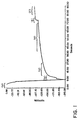
- Figure 1 illustrates the potential response, as a function of time, of a potentiometric potassium ion sensor utilized in the present invention.
- the measurement cycle is initiated electronically, contact being made between the array of sensors, which are mounted preferably on a disposable assembly ( See , for example, prior co-pending U.S. Application Serial No. 07/245,102 ), and the external computational means.
- the external computational means During this initial period, all the sensors are grounded.
- the first fluid is caused to flow over and make contact with the sensor array.
- the potential of the potentiometric sensor drifts monotonically, essentially in an exponential manner.
- the fluid change is made after about 72 seconds, though clearly, the introduction of the second fluid can be made much sooner if obtaining this potassium ion concentration is the only objective of the analytical cycle.
- the first time window can be selected to fall at any suitable time after the first fluid is in place over the sensors and prior to the introduction of the second fluid.
- the second time window, in which the second set of signal measurements is performed, is begun preferably soon after the fluid change is made.
- Calculation of the sensor response that is, the change in potential reading between the first and second fluid (the delta voltage) is performed once an adequate data set has been obtained.
- the present algorithm used to calculate the sensor's response performs two linear least-squares fits. One least-squares fit is performed in the first fluid time window; the other is done in the second fluid time window.
- Some examples for deriving the delta response value include, but are not limited to, a linear/linear extrapolation, a linear/mean calculation, a mean/mean approach or a mean/linear method, to name a few.
- the fit to the first time window is extrapolated forward to an estimated fluid transition point, the middle of the transition period.
- the fit to the second time window is extrapolated backward to the same estimated transition point, although clearly, it is not necessary to specifically select the fluid transition point at the midpoint as some other suitable point may also be selected.
- the arithmetic difference between these extrapolated voltages is the sensor's delta response.
- the ratio between the extrapolated values is calculated if currents derived from an amperometric sensor are being measured.
- concentration in the sample fluid of the analyte species of interest can then be determined based on the known chemical activity (concentration) of the analyte in the calibrant fluid.
- E o is a constant independent of T, A or B.
- a correction of the calculated chemical activity of the analyte in the unknown or sample fluid can be obtained by applying the Henderson equation (2) where the term Ej is included in equation (1) and taking into consideration differences in ionic strength and matrix effects between the calibrant and sample fluids, which differences are usually manifested as a slight response of ⁇ the reference electrode: where z i is the charge, ⁇ i is the mobility, c i is the molar concentration of species i and ⁇ and ⁇ are transfer coefficients.
- the linear fit to the calibrant time window is extrapolated forward, as before, but to the midpoint of the sample time window.
- the difference between the extrapolated value from the calibrant fit and the mean sample value is the delta response.
- the ratio of the extrapolated value of one time window to the midpoint value of the second time window can be calculated also, if desired.
- the mean/linear case reverses the direction of the extrapolation used in the preceding approach, and the execution of the mean/mean method of calculation should be fairly evident.
- the method of choice for calculating the sensor response depends on the characteristics of that sensor and may be best determined through routine experimentation. However, the quality of the sensor response measurements will certainly have an impact on which method is most appropriate. For instance, a f-irly large difference between the slopes of the data points in the first and second time windows may indicate that a linear method may lead to a skewed result and that a mean value of the particular time window may be more appropriate.
- the computational methods utilized during data collection, manipulation and analysis may be enhanced to look at drift rates (slopes) as data points are collected in each time window to determine the "smoothness" of the window.
- first and second derivatives of fully sampled time windows can be compared using "enhanced" computational methods.
- the calibrant fluid should contain a known concentration of the preselected analyte.
- the calibrant fluid may comprise a wet gas but is preferably comprised of an aqueous liquid.
- the chosen concentration of the preselected analyte in the calibrant is preferably similar to that expected to be encountered in the unknown sample.
- preservatives e.g., p-hydroxybenzoate, phenylmercuricacetate, p-aminobenzaldehyde and the like
- the calibrant fluid is an aqueous solution of several analytes whose concentrations are similar to those expected to be determined in an unknown sample, usually whole blood.
- the practice of the present method is simplified if a small volume of blood is used to displace a small volume of calibrant fluid. That is, the first fluid is preferably the calibrant, and the second fluid is preferably the blood sample. It should be evident, however, that the present method is not so limited, and the sequence and nature of the fluids introduced to the sensors is a matter of choice.
- the wet-up phenomena can be controlled to a high degree of confidence, along with the physical dimensions and material properties of the sensors and reference electrode.
- the output shows that the wet-up has proceeded to a level where ⁇ t ⁇ 3 ⁇ the slow rate of change can be treated as a linear drift and this linear relationship can reliably project the sensor's output forward in the time domain for some brief period, e.g., 30 seconds.
- This capability becomes crucial when one changes the solution in contact with the sensor and reference electrode, e.g., (unknown) sample (known) calibrant and compare the readings between the two fluids. In this manner the need for strictly simultaneous introduction of calibrant to the "reference" electrode and the unknown sample to the "working" electrode is circumvented.
- FIG. 1 A series of Figures (1-3) follows to illustrate the wet-up dynamics of several different wholly microfabricated sensors with respect to a fully wet-up conventional flow through silver-silver chloride reference electrode, as well as the performance of such sensors versus a microfabricated reference electrode that undergoes similar wet-up effects. It can be seen that a linear fit of the reading in one fluid enables one to predict accurately what the value of the reading should be at later times for comparison with a subsequent reading in a second fluid.
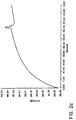
- Figures 2a to 2e show the response characteristics for a potassium, sodium, chloride, urea and on-board microfabricated reference electrode, respectively, versus a standard Corning reference electrode, with the change from calibrant to the unknown (sample) fluid occurring after about 50 seconds. (In these and subsequent Figures the response of the sensor prior to introduction of the calibrant fluid is not shown.) The wet-up response for all of these ISEs is similar, showing a roughly linear drift rate after about 40 seconds. It is particularly important to note that the on-board microfabricated reference electrode ( Figure 2e) does not respond to the fluid change, beyond minor correctable ionic strength and matrix effects. Hence it may be used advantageously as the actual reference electrode for the potassium, sodium, chloride, and urea sensors.
- an empirical approach can be employed which involves determining the accuracy and precision for each of the first order relationships.
- a Linear/Linear method is found to be superior for the potassium, sodium and chloride sensors.
- the urea sensor which has a slower response-time, provides best results when a Linear/Mean fit is used.
- the exact location and duration of the data acquisition windows can also be determined in this fashion.
- the current output in amperometric measurements is system dependent. That is, the result is dependent upon the geometry and transport properties of the overlaid structures, as well as the surface properties of the electrode.
- the current response will be directly proportional to the bulk concentration of the analyte.
- the absolute current at any given bulk concentration usually increases over the time domain, as the dry-stored overlaid structures hydrate; that is, the transport rate across the membranes increases.
- At least two amperometric sensor signals are determined in each data aquisition time window (again, there should be at least two time windows, one for each fluid).
- one of the sensor signals determined in each time window e.g., the calibrant fluid time window
- the other of the sensor signals, still in the same time window is measured at a second applied potential.
- a fluid change is then made, and the above signal measuring process is repeated. If, for instance, the applied potential is stepped up from one value to a higher applied potential in the first time window, then in the second time window, it may be convenient to step down from that higher value to a lower applied potential.
- the range of applied potentials at which the individual signal measurements may be varied according to the needs of the particular application.
- such applied potentials may be chosen to lie in the range of about 100 to about 300 mV.
- the one of at least two signal measurements in a given time window is carried out at an applied potential of about 125 mV and the other measurement at about 225 mV.
- the signal values obtained at each applied potential is then plotted on a signal (e.g., current) versus applied potential curve and the slope of the line defined by such values calculated and compared for each time window. In this manner, the slope of the line obtained for a calibrant fluid having a known concentration of a preselected species may then be compared with that recorded for a line derived from a sample fluid.
- the applied voltages are centered about the region in which the net current is or close to zero. In this way, the contribution of interfering redox processes to the total current or the effect of any bias current associated with measuring electronics is minimized, and the best estimate for the maximum slope is obtained.
- the mode of operation can be especially complex for amperometric sensors which are active devices, unlike potentiometric sensors which are electrically passive.
- An amperometric sensor measures the rate of electron transfer across the electrode-solution interface.
- the electrode surface plays a catalytic role in such electron transfer (redox) reactions; therefore, the current is not only dependent upon the surface area of the sensor but also upon the catalytic activity of the surface.
- the present novel operational method is useful for rapidly activating the electrode surface of a dry-stored amperometric glucose sensor without deleteriously affecting the overlaid structures.
- This activation makes an important contribution to reducing the overall apparent wet-up RC time-constant for the sensors.
- the present activation is carried out in the presence of a non-corrosive fluid but prior to data acquisition and before the sensor has attained a fully wet-up state.
- a set of pulse groups is applied to the glucose sensor in the presence of the calibrant or sample fluids.
- This process comprises changing (cycling) the applied potential between values of opposite sign (e.g., +1 V to -1 V).
- the pulses are applied conveniently at full increment steps (i.e., at full ⁇ 1 V steps).
- it should be apparent to those of ordinary skill that such cycling may also be accomplished in a variety of other ways including, but not limited to, (i) pulsing; (ii) intermediate incremental steps to the desired positive potential, followed by intermediate incremental steps to the desired negative potential; (iii) linear potential sweeps to the respective desired potentials; and (iv) non-linear potential sweeps or such sweeps which resemble smooth sinusoidal waves.
- the first two pulse groups in the set have a magnitude and duration sufficient to activate the catalytic surface of the electrode. These pulse groups may also promote hydration of the overlaid structures.
- the third pulse group in the set serves to reduce the initial rate of change in current upon application of the actual operating potential.
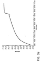
- the time zero corresponds to the time at which the sensor comes into contact with the fluid, calibrant in the preferred instance)
- Figure 5b shows in more detail the response of the activated sensor, at the operating potential, to a 5 mM glucose calibrant solution (26-53 sec) followed by a 10 mM human serum (from about 54 sec).
- the analytical value of the glucose sensor is clearly apparent, with a significant current being observed for both fluids and in which the current shows an increase after the sensor is exposed to a biological fluid having a glucose concentration which is higher than the calibrant solution.
- the sensor gives a linear current response at a range of 0.1-30 mM glucose.
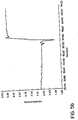
- Figure 5c suggests that the sensor is almost fully activated because there is only a marginal increase in the maximum hydrogen peroxide oxidation and reduction currents when the entire pulsing sequence is repeated on the same sensor.
- a viable alternative to cycling the applied potential involves galvanostatic control over the sensor activation with a constant current source being applied to the sensor until the required potential attains some predetermined value or rate of change.
- Another alternative for measuring the current output of the sensors, to determine its level of activation involves making a conductivity measurement between two electrodes, one which is the sensor.
- the pulsing sequence for hydrogen peroxide measuring sensors are as follows: pulse groups 1 and 2 should be of a duration of about 5 seconds with limits of +0.7 to +1.2 V at the oxidizing end and -0.7 to -1.2 V at the reducing end, which pulses may or may not be applied symmetrically. A single extended negative pulse followed by the standard sequence may also be applied advantageously.
- the inventors have observed that negative pulses are an important aspect of the activation process, and they speculate that the activation process is likely to be associated with the reduction of one or more types of functional groups of the iridium electrode. However, the inventors do not wish to be bound by the present speculation nor do they wish to limit the scope of the present invention by making specific interpretations of the surface activation process on a molecular level.
- the third pulse group should be selected from groups in which the final potential step is in the range +400 mV to +800 mV.
- the current recorded for the 5 mM glucose calibrant fluid shows that the sensor has attained a sufficient degree of wet-up and activation.
- data is recorded in the first time window for later extrapolation.
- the calibrant fluid is forced to waste and the biological fluid (sample) placed over the sensor.
- An advantage of thin-film microfabricated biolayers is that the response-time (i.e., the time it takes for the current to change to a value which is proportional to the. bulk concentration of the analyte in the second fluid) is fast, usually less than 5 seconds. It is this additional property of the present microfabricated devices that contributes to the success of the present analytical methods.
- the data is recorded in the second time window.
- the selection of an appropriate location for the data acquisition window and the choice of the data fitting computational method are based on empirical calculations of the accuracy and precision attainable with each of the fits.
- a Linear/Mean fit is preferred for the glucose sensor.
- a glucose sensor comprising an iridium electrocatalyst at which hydrogen peroxide produced by an enzymatic reaction is measured by means of electrochemical oxidation at an operating potential of +350 mV versus an on-board silver-silver chloride reference electrode.
- An alternative method for operating this sensor is based upon electrochemical reduction of hydrogen peroxide. This operation is achieved by applying an operating potential in the range of zero mV to -250 mV, preceded by pulse groups similar to 1 and 2 above, but with pulse group 3 having a final potential set in the range of -200 mV to -500 mV.
- An oxygen sensor of the type disclosed in the U. S. Application Serial No. 07/432,714, with a gold electrocatalyst suitable for oxygen reduction, may also be operated with this type of activation method.
- pulse group 3 is preferably chosen to fall in the range of -600 mV to -800 mV, where an operating potential in the range of -400 mV to -550 mV is contemplated for oxygen reduction at a gold electrode.
- the object of the computational method is the determination of the bulk concentration of the metabolite.
- the sensor should not perturb the bulk concentration of the metabolite if the measurement is to be of analytical value.
- the object of the sensor computational method is the determination of the rate of change in concentration of an electroactive species which is consumed or produced while the assay is in progress, which rate reflects the enzyme activity present in the system.
- Sensors appropriate for enzyme and enzyme-linked immunoassays are disclosed once again in U.S. Application Serial No. 07/432,714.
- the computational method can be modified as follows: after a set of activation pulse groups is applied and measurement of a calibrant current is performed, as described above, substrates or reagents for the enzyme or enzyme-linked immunoassay are introduced to the sensor. After a brief induction or mixing period the current changes steadily, and the initial rate of change, di/dt, is then computed ( See , Figure 6). From the rate of change in the current and the known current electroactive species corresponding to a certain concentration in the calibrant, the rate of increase in its concentration can be estimated.
- This rate can be expressed as the enzyme activity, that is moles of substrate consumed per unit time at a certain temperature, pH etc. It is important to note that if the data collection period extends over several minutes, the above-mentioned pulse groups wet-up the sensor structure to a sufficient extent such that the calibrant signal can be readily extrapolated forward in the time domain. Otherwise the rate measurement, which is based on the initial sensor response in the presence of calibrant fluid (if calibrant is introduced prior to introducing the sample), may be severely compromised (Refer to earlier discussions related to the importance of making the calibrant and sample measurements close in time). The use of microfabricated immunosensors in this manner makes it possible to obtain rate measurements prior to the sensor attaining a fully wet-up state.
- Advanced operational methods can also be used to make the system "smart.” Such methods can be applied during the real time operation of the sensors or during post data collection treatments. See in particular, the flexible methods for governing the activation of amperometric sensors, assessing the propriety of a given set of data points or determining the best position for e data window , to name a few.
- these methods may include alternatives to applying the identical pulse sequence to all amperometric sensors which may be present in the array.
- the operational method can be modified such that pulse groups 1 and 2 are applied until the observed peak current associated with each potential pulse has reached a finite value, until the charge passed in each pulse has reached a finite value, until the charge passed for the entire pulse sequence has reached the finite value or until the RC time constant for the sensors after a given pulse is within some predetermined range of values.
- pulse groups 1 and 2 may be applied until the rate of change between successive pulses, in terms of peak current, charge passed or RC time constant, is within some preselected range.
- Advanced methods for error recovery can also be implemented.
- computational methods can be put in place for detecting the presence of glitches in the data set, whether such glitches are isolated or numerous, or whether they may be associated with common background noise.
- An advanced method for sensing integrity failures may suggest appropriate solutions, such as the application of median filters.
- another data. set may be chosen which is derived from a separate data window stored in the system. For example, if the sample causes an abnormally slow response from the sensor, gives rise to non-ideal waveforms upon contact with the sensors or, generally, does no provide well-behaved waveforms, the first and second time windows may not be positioned in the best place initially. The presence of slight defects in the sensor may also give rise to less than desirable responses.
- the maximum value for the sample or second fluid may not have yet been reached before a second signal measurement is performed (i.e., a second time window is selected for comparison with the first time window associated with the first or calibrant fluid).
- the signal associated with the sample may degrade rapidly soon after reaching the maximum value, thus providing a lower value than what should have been observed if the signal had not degraded.
- the computational method may search for the proper data collection window and locate the maximum value which provides a better estimate of the concentration of the preselected analyte species. Also, even if certain error limits are reached or exceeded, a reinspection of the value of the slope and the quality of the overall drift may prompt the instrument to accept the values obtained. In certain cases, the value of the delta drift can override a data window with an unusual number of glitches or a high level of noise. Of course, different methods for extrapolating the slopes and calculating the difference between the signal measurements may be selected. These non-ideal responses may be encountered more frequently with sensors of increased functional complexity.
- the electrical conductance is a function of the nature of the particles, the medium and the fraction of the total volume occupied by the particles.
- the electrical conductance is a function of the nature of the particles, the medium and the fraction of the total volume occupied by the particles.
- the entire period of data acquisition in the calibrant and in the blood takes only about one second.
- the a.c. conductivity is measured at a frequency which is selected to be sufficiently high to minimize the impedance at the sensor-fluid interface, and sufficiently low to minimize capacitive coupling across the erythrocyte cell membrane.
- a preferred frequency is about 50 KHz.
- the calibrant fluid is then removed and blood introduced.
- the measurement cycle is then repeated with the actual measurement time being selected so that the blood is in a quiescent state, but before a significant degree of erythrocytes have settled.
- the conductivity sensor comprises two noble metal electrodes microfabricated on a planar surface and designed with the appropriate geometry.
- Such conductivity measurement may also be utilized to determine the success or failure of the fluid change operation. That is, stored values of predicted fluid conductivities can be compared to the observed measurements to provide a quality assurance method for detecting the presence of an adequate intervening air segment between fluids, the failure of the calibrant fluid to move to waste, or other such system failures associated with the fluidics movements.
- a system most attractive in the clinical setting is not limited to discrete measurements of single analytes.
- an array of sensors designed to make a multiplicity of discrete measurements of a range of different analytes in biological fluids is preferred.
- This array of sensors is preferably exposed to a single, common calibrant fluid which is removed after all of the sensors have been calibrated. Only then can the second (sample) fluid be introduced to the sensors.
- Such an integrated setting means that all of the sensors must be chemically and electrically compatible: that is, they must wet-up and respond at approximately the same rate without interfering with one another.
- sensor compatibility and system integration is enhanced if the pulsing sequence, used in amperometric measurements, is completed prior to performing potentiometric measurements because the high current flow in solution associated with pulsing can undermine the integrity of the potentiometric signal.
- a current of ca. 10 -3 A flows in the solution between the pair of metal electrodes. While this current may seem small, it is about six orders of magnitude greater then that measured in the amperometric based analyses. Again, during the period when the amperometric sensors are being pulsed, a maximum current of, ca. 10 -6 A, also flows.
- the conductivity sensor be operated after activation of the amperometric sensors but before amperometric data are acquired. After the fluid change, the amperometric data acquisition is performed before the second conductivity measurement is made.
- a series resistor, ca. 10 5 ohm may also be used to protect amperometric sensors during the a.c. conductivity measurements.
- the conductivity sensor may also be used to distinguish the general composition of a fluid, i.e., whether the sensor is in contact with calibrant fluid, serum or whole-blood, or for that matter no sample at all, i.e., air. Because many of the sensors display matrix effects, as discussed previously above, this measurement may be used to make the appropriate correction to the calculation of the concentration of the preselected analytes.
- a fluid grounding electrode in close proximity to the potentiometric sensors to absorb excess charge generated in the fluid when the conductivity sensor is activated. This excess charge may have the undesirable effect of polarizing the potentiometric membranes. Moreover, the membranes must be depolarized rapidly if they are to be of analytical value.
- the conductivity measuring sensor may be placed on a separate chip from that of the potentiometric sensors.
- these sensor structures are actually fabricated on a silicon wafer with an insulating layer, ca. 0.5 10 -6 m in thickness, of silicon dioxide.
- the underlying silicon is a semiconductor which means that capacitive coupling between sensors presents a possible signal interference. Separating the sensors on different chips obviates this potential problem.
- Chart II there is shown a more detailed flow chart of the Data Collection method.
- data collection may be accomplished in several different ways, including simply sequentially measuring and storing data.
- the method of the preferred embodiment permits verifying integrity of the measurements in real time, while collecting input data.
- this on-line verification method permits early detection and, possibly, elimination of spikes, glitches, and other noise in the data.
- time windows can be determined intelligently at flexible intervals where the data points are not significantly affected by noise. Such smooth time windows can thus be located readily.
- the Data Collection process begins at block 21, where each data point is measured.
- Data acquisition involves taking an analog signal and recording it in digital format in the appropriate memory location.
- a set of 80 data points every one-sixtieth of a second are preferably recorded.
- the sampling rate is set at 80 data points every one-fiftieth of a second.
- the average value of this set is then calculated, and this value is taken as a "single" data point. These "single" data points are then used in further calculations.
- the electronics are designed to be appropriate for high impedance potentiometric sensors with sufficient resolution over the expected range of measurements.
- the electronics for amperometric sensors includes current to voltage convertors designed to have sufficient resolution over the expected range of current measurements.
- a counter (DATA_COUNTER), which keeps track of the aggregate number of data points collected within a time window, is incremented by one.
- the DATA_COUNTER is initialized to zero prior to acquisition of the first data point of a given time window.
- the method flow then passes to test 23, where the total number of collected data points (DATA_COUNTER) is compared to the number of data points of a selected sliding window set (SLIDING_POINTS).
- the size of a sliding window is selected on the basis of a trade-off between the computational time and precision of error detection. In this instance, a seven point sliding window is selected from a twenty-five point time window. According to test 23, if the total number of acquired points is less than the size of one sliding window, the control returns to block 21, where another data point is acquired. Otherwise, control is transferred to test 24.
- Test 24 is provided to locate the basis window.
- the basis window is defined as the first sliding window, and remains the same throughout the data acquisition process for a given time window. It should be apparent to one of ordinary skill in the art that there are other methods of selecting a basis window.
- a basis window can be defined as a sliding window which is "behind" the current sliding window by one or more points.
- SLIDING_POINTS if an exact number of SLIDING_POINTS are collected, method flow is transferred to block 29; otherwise, the total number of collected points is greater than the size of one sliding window, and method flow passes to block 25.
- a new sliding window set is formed and a recursive form of the linear regression method is used to compute the slope of a sliding window. In this instance, a new sliding window set is created whenever flow enters block 25. Therefore, a first sliding window consists of the following data points: ⁇ 2, 3 ... (SLIDING_POINTS + 1) ⁇ , and each subsequent sliding window is formed by including a newly acquired data point and eliminating the first data point of the previous sliding window set.
- the method flow passes to block 26, where the slope of the basis window is compared to the slope of the current sliding window, and the ratio of the slopes is computed. Then at block 27, the integrity of a current sliding window data set is verified. If the ratio of the slopes is not within acceptable bounds, the output of such sensor is deemed to contain an error. One can set, for example, an upper bound of 2.5 for the ratio. If, however, the basis window has a value of zero, a difference instead of a ratio is used.
- a flag (ERROR) is set.
- the ERROR flag is simply a bit.
- the ERROR flag value might contain a pointer to a specific data point that causes the ratio of the slopes to be out of bounds.
- Chart III shows schematically the steps of the Data Analysis stage of the method in which analyte concentrations are determined from each sensor measurement.
- data points for the first (e.g., calibrant) and second (e.g., sample) time windows have been collected and stored in appropriate memory locations.
- Test blocks 41-47 occur for each active sensor in the array, while test blocks 48-51 occur once for the entire array.
- test 41 checks whether an error has been detected at the Data Acquisition stage by testing the status of the ERROR bit. If the ERROR bit is set, method flow passes directly to block 42, where error recovery is performed. Otherwise (i.e., no errors at Data Acquisition stage), flow passes to block 42.
- a linear regression is applied to the data points of each window to approximate the drift rates (slopes) of the data window.
- higher order regressions i.e., those that approximate 2nd, 3rd, ..., nth order functions, can be implemented easily.
- the order of the applied regression should be determined according to the nature of the sensors' degree of wet-up and waveform in the selected time window intervals.
- MIN_SLOPE, MAX_SLOPE, MAX_DIFF, MIN_MEAN, MAX_MEAN_1 and MAX_ERROR are expected ranges of the above parameters.
- the specific values are determined experimentally, based on the predictable characteristics of the sensors' response curve. Table I lists some suggested values for the various data window parameters.
- the limit on the difference (in mV/s) between the value of the slope in each time window is set at a maximum of 0.50, 0.30, 0.30 and 1.00 for the chloride, potassium, sodium and BUN sensors, respectively.
- the observed waveform for the second fluid, such as glucose, in contact with the microfabricated amperometric sensors can exhibit a maximum or minimum value; consequently a linear/mean fit is preferred.
- test 43 If one of the above tests indicates that the measurement is out of range, all the measurements generated by a particular sensor are discarded as unreliable. However, the present method provides for error recovery of corrupt data. Accordingly, if an error is detected at test 43, the method flow passes to test 44. If no errors are detected, control is transferred to block 47, where the sensors' responses are determined.
- Test 44 determines whether a previous attempt to correct errors has already been made.
- a variable "FIRST_TIME” is incremented by one. (FIRST_TIME is initialized to zero at the beginning of the Data Analysis for each time window.)
- a value of FIRST_TIME that is greater than 1 indicates that a previous attempt to correct errors has been made. Because the flow returned subsequently to test 44, error recovery failed once and should not be repeated. In this case, method flow passes to block 46, where the "FAILED” bit is set to indicate that this particular measurement has failed, and that the only further processing remaining for such sensor involves displaying an error message at block 51. Otherwise, the value of FIRST_TIME is one and the flow passes to block 46, where error recovery is attempted.
- Error recovery can be implemented in a variety of ways. For example, noise and spikes in the data can be eliminated by known digital techniques, such as median filters and the like described previously, i.e., the re-evaluation of observed values ( See , e.g., p. 29.) Another method may involve the interpolation of a curve on the basis of the first several points of a given time window and the rejection of those points that deviate significantly from the interpolation. In most cases, it may be desirable to collect more data points than that required for a given time window, so that error recovery may be accomplished by selecting an alternative time window set. From error recovery at block 46, method flow turns back to block 42 where the points of the corrected data set are interpolated and new slopes and errors of approximation are computed.
- the control is transferred to block 47 where the sensors' responses are determined by relating measurements in the first (calibrant) time window to those in the second (sample) time window.
- the analytical value of interest is the delta response, which is the difference between the amplitudes measured at a selected point of an analyte and calibrant response curves.
- the delta response corresponds to the ratio of the respective amplitudes.
- the particular sensor's delta response is then calculated in one of the many different ways including, but not limited to, a Linear/Linear delta, Linear/Mean delta, Mean/Mean delta, Mean/Linear delta, Maximum/Linear delta, Linear/Maximum delta, Linear/Minimum delta and Minimum/Linear delta approaches.
- the fit to the first window is extrapolated forward to an estimated fluid transition point, i.e., the midpoint between the first window and the second window.
- the fit to the second window (sample) is extrapolated backward to the same estimated transition point. The difference between these extrapolations is the particular sensor's delta response.
- the linear fit to the calibrant is extrapolated forward to the midpoint value of the sample window and compared to the midpoint value of the sample response curve.
- the Mean/Linear approach the previous sequence is reversed.
- the delta response is the difference between the midpoint of the sample window and the midpoint value of the calibrant window.
- the Linear/Maximum, Maximum/Linear, Linear/Minimum and Minimum/Linear methods are analogous to Linear/Mean and Mean/Linear methods, except that the mean value is replaced by the maximum or minimum value of the corresponding time window.
- the Linear/Linear method is found to be superior for the potassium, sodium and chloride sensors.
- a Linear/Mean method is best for the present embodiment of the glucose and urea sensors.
- the flow passes to block 48.
- the response of the reference electrode is subtracted from the delta response determined in block 47.
- certain corrections are made for a slight response of the reference electrode due to matrix effects and differences in ionic strength of the fluids.
- the flow passes to block 49, where, for poientiometric sensors, Equation 1 and coefficients derived from Equation 2, as described above, are applied to determine analyte concentrations. For amperometric sensors, Equation 3 is applied.
- the results are appropriately scaled in order to derive standardized values.
- block 51 provides a display of the calculated concentrations or a display of an appropriate message if aberrant values are found.
Landscapes
- Health & Medical Sciences (AREA)
- Life Sciences & Earth Sciences (AREA)
- Chemical & Material Sciences (AREA)
- Hematology (AREA)
- Analytical Chemistry (AREA)
- Physics & Mathematics (AREA)
- Molecular Biology (AREA)
- Biochemistry (AREA)
- General Health & Medical Sciences (AREA)
- General Physics & Mathematics (AREA)
- Immunology (AREA)
- Pathology (AREA)
- Chemical Kinetics & Catalysis (AREA)
- Electrochemistry (AREA)
- Investigating Or Analyzing Materials By The Use Of Electric Means (AREA)
- Investigating Or Analysing Biological Materials (AREA)
- Investigating Or Analysing Materials By Optical Means (AREA)
Claims (68)
- Verfahren zum Bestimmen der Konzentration zumindest einer vorausgewählten Analytspezies, die in einem Probenfluid vorliegt, mit folgenden Schritten:(a) Bereitstellen einer externen Rechenvorrichtung, einer Referenzelektrode und mindestens einem im wesentlichen trocken gelagerten mikrofrabrizierten Sensor, der fähig ist, eine Antwort auf Änderungen in der Konzentration einer vorausgewählten Analytspezies zu zeigen, wobei die Antwort relativ zu dem Befeuchtungsverhalten des Sensors schnell ist, wenn er mit einem Fluid in Kontakt gebracht wird;(b) Herstellen eines elektrischen Kontakts zwischen dem Sensor, der Referenzelektrode und der externen Rechenvorrichtung;(c) den Sensor und die Referenzelektrode mit einem Kalibrierfluid in Kontakt bringen;(d) Durchführen einer ersten Signalmessung in einem ersten Zeitfenster in der Gegenwart des Kalibrierfluids, bevor der Sensor von einem trockenen Zustand in einen voll ausgeglichenen befeuchteten Zustand übergegangen ist;(e) Verdrängen des Kalibrierfluids nach dem Durchführen der ersten Signalmessung;(f) den Sensor und die Referenzelektrode mit dem Probenfluid in Kontakt bringen,(g) Durchführung einer zweiten Signalmessung in einem zweiten Zeitfenster in der Gegenwart des Probenfluids, bevor der Sensor von dem trockenen Zustand in den voll ausgeglichenen befeuchteten Zustand übergegangen ist; und(h) Verbinden der ersten und zweiten Signalmessungen, um die Konzentration der vorausgewählten Analytspezies in dem Probenfluid durch ein Rechenverfahren zu bestimmen, das die relativ schnelle Antwort des Sensors auf Änderungen in der Konzentration des vorausgewählten Analyts von dem langsameren Befeuchtungsverhalten des Sensors und der Referenzelektrode unterscheidet.
- Verfahren nach Anspruch 1, bei dem der mikrofabrizierte Sensor ein Widerstandsmessungssensor ist, der eine Antwort auf Änderungen in der Konzentration einer vorausgewählten Analytspezies zeigt, wobei die Referenzelektrode fähig ist, ein gutes Referenzpotential für eine Zeitdauer zu halten, die ausreichend ist, um den Abschluß von zumindest zwei Signalmessungen zu erlauben, bevor der Sensor einen voll ausgeglichenen befeuchteten Zustand einnimmt, und.die Referenzelektrode im wesentlichen trocken gelagert wurde.
- Verfahren nach Anspruch 1, bei dem ein Feld mikrofabrizierter Widerstandsmessungs- und Strommessungssensoren in Schritt (a) bereitgestellt werden, von denen jeder eine Antwort auf Änderung in der Konzentration einer anderen vorausgewählten Analytspezies zeigt,
welches Feld einzelne Sensoren und zumindest zwei Referenzelektroden umfaßt, die fähig sind, ein gutes Referenzpotential für eine Zeitdauer zu halten, die hinreichend ist, um den im Abschluß von zumindest zwei Signalmessungen zu erlauben, bevor der Sensor eine voll ausgeglichene Befeuchtung erreicht, wobei eine Referenzelektrode an die Widerstandsmessungssensoren angeschlossen ist, wenn die andere Referenzelektrode an die Strommessungssensoren angeschlossen ist, und jeder der Sensoren im wesentlichen trocken gelagert wurde;
und bei dem das Verbinden der ersten und zweiten Sätze von Signalmessungen die Bestimmung der Konzentration einer Vielzahl der verschiedenen vorausgewählten Analytspezies in dem Probenfluid bietet. - Verfahren zum Bestimmen des Verhältnisses der Konzentrationen einer vorausgewählten Analytspezies, die in zwei Fluiden vorkommt, mit den folgenden Schritten:(a) Bereitstellen einer externen Rechenvorrichtung und mindestens eines trocken gelagerten mikrofabrizierten Sensors, der fähig ist, eine Antwort auf Änderungen in der Konzentration einer vorausgewählten Analytspezies zu zeigen, welche Antwort relativ zu dem Befeuchtungsverhalten des Sensors schnell ist, wenn er mit einem Fluid in Kontakt gebracht wird;(b) Bereitstellen einer trocken gelagerten mikrofabrizierten Referenzelektrode, die fähig ist, ein gutes Referenzpotential für eine Zeitdauer zu halten, die ausreichend ist, um den Abschluß von zumindest zwei Signalmessungen zu erlauben, bevor der Sensor von einem trockenen Zustand in den voll ausgeglichenen befeuchteten Zustand übergegangen ist, und ein Befeuchtungsverhalten zeigt, das ähnlich zu dem ist, das der Sensor zeigt, wenn er mit einem Fluid in Kontakt gebracht wird;(c) Herstellen eines elektrischen Kontakts zwischen dem Sensor, der Referenzelektrode und der äußeren Rechenvorrichtung;(d) den Sensor und die Referenzelektrode mit einem ersten Fluid in Kontakt bringen;(e) Durchführen einer ersten Signalmessung in einem vorausgewählten ersten Zeitfenster in der Gegenwart des ersten Fluids, bevor der Sensor und die Referenzelektrode von dem trockenen Zustand in den voll ausgeglichenen befeuchteten Zustand übergegangen sind;(f) Verdrängen des ersten Fluids nach dem Durchführen der ersten Signalmessung;(g) den Sensor und die Referenzelektrode mit einem zweiten Fluid in Kontakt bringen;(h) Durchführen einer zweiten Signalmessung in einem vorausgewählten zweiten Zeitfenster in der Gegenwart des zweiten Fluids, bevor der Sensor und die Referenzelektrode von dem trockenen Zustand in den voll ausgeglichenen befeuchteten Zustand übergegangen sind; und(i) Verbinden der ersten und zweiten Signalmessungen, um das Verhältnis der Konzentrationen von der Analytspezies in dem ersten und zweiten Fluid durch ein Rechenverfahren zu bestimmen, das die relativ schnelle Antwort des Sensors gegenüber Änderungen in der Konzentration des ausgewählten Analyts von dem langsameren Befeuchtungsverhalten des Sensors und der Referenzelektrode unterscheidet.
- Verfahren nach Anspruch 4, bei dem der mikrofabrizierte Sensor ein Strommessungssensor ist.
- Verfahren nach Anspruch 1, 2 oder 3, bei dem die Reihenfolge, in der der Sensor, die Referenzelektrode oder das Feld davon mit dem Kalibrierfluid und dem Probenfluid in Kontakt gebracht wird, umgedreht ist.
- Verfahren nach Anspruch 6, bei dem die erste und die zweite Signalmessung oder deren Sätze in der Gegenwart von dem Probenfluid bzw. dem Kalibrierfluid durchgeführt werden.
- Verfahren nach dem Anspruch 4 oder 5, bei dem das erste Fluid ein Kalibrierfluid ist.
- Verfahren nach Anspruch 8, bei dem das zweite Fluid ein Probenfluid ist.
- Verfahren nach Anspruch 4 oder 5, bei dem das erste Fluid ein Probenfluid ist.
- Verfahren nach Anspruch 10, bei dem das zweite Fluid ein Kalibriermittel ist.
- Verfahren nach Anspruch 1, 2, 3, 4 oder 5, das des Weiteren das Bereitstellen eines Leitfähigkeitssensors umfaßt, der fähig ist, die Leitfähigkeit eines Fluids zu messen, das mit ihm in Kontakt gebracht ist.
- Verfahren nach Anspruch 1, 2 oder 3, das des Weiteren das Durchführen einer ersten Leitfähigkeitsmessung in der Gegenwart des Kalibrierfluids umfaßt.
- Verfahren nach Anspruch 4 oder 5, das des Weiteren das Durchführen einer ersten Leitfähigkeitsmessung in der Gegenwart des ersten Fluids umfaßt.
- Verfahren nach Anspruch 13, das des Weiteren das Durchführen einer zweiten Leitfähigkeitsmessung in der Gegenwart des Probenfluids umfaßt.
- Verfahren nach Anspruch 14, das des Weiteren das Durchführen einer zweiten Leitfähigkeitsmessung in der Gegenwart des zweiten Fluids umfaßt.
- Verfahren nach Anspruch 13, bei dem die erste Leitfähigkeitsmessung vor dem Durchführen der ersten Signalmessung oder dessen Satz davon durchgeführt wird.
- Verfahren nach Anspruch 14, bei dem die erste Leitfähigkeitsmessung vor dem Durchführen der ersten Signalmessung durchgeführt wird.
- Verfahren nach Anspruch 15, bei dem die zweite Leitfähigkeitsmessung nach dem Durchführen der zweiten Signalmessung oder dem Satz davon durchgeführt wird.
- Verfahren nach Anspruch 16, bei dem die zweite Leitfähigkeitsmessung nach dem Durchführen der zweiten Signalmessung durchgeführt wird.
- Verfahren nach Anspruch 3 oder 5, das des Weiteren das Aktivieren des Strommessungssensors oder des Feldes davon umfaßt.
- Verfahren nach Anspruch 21, bei dem das Aktivieren des Strommessungssensors das Unterwerfen des Strommessungssensors einer Reihe von Potentialänderungen in der Gegenwart des Kalibrierfluids oder des ersten Fluids umfaßt.
- Verfahren nach Anspruch 22, bei dem die Potentialänderungen das zyklische Ändern des anliegenden Potentials zwischen Werten entgegengesetzten Vorzeichens relativ zu der Referenzelektrode umfaßt.
- Verfahren nach Anspruch 22, bei dem die Reihe von Potentialänderungen eine erste Gruppe umfaßt, die zumindest zehn Wiederholungen eines Zyklus aufweist, in dem das anliegende Potential auf einem ersten Wert gehalten wird, und dann auf einen zweiten Wert gleicher Größe aber mit entgegengesetzten Vorzeichen zu dem ersten Wert umgeschaltet wird.
- Verfahren nach Anspruch 24, bei dem die Reihe von Potentialänderungen des weiteren eine zweite Gruppe umfaßt, die zumindest fünf Wiederholungen eines Zyklus aufweist, bei dem das anliegende Potential auf einem ersten Wert gehalten wird, und dann auf einen zweiten Wert gleicher Größe aber mit entgegengesetzten Vorzeichen zu dem ersteren Wert umgeschaltet wird.
- Verfahren nach Anspruch 25, bei dem die Reihe von Potentialänderungen des Weiteren eine dritte Gruppe umfaßt, die zumindest fünf Wiederholungen von einem Zyklus aufweist, bei dem das anliegende Potential auf einem ersten Wert gehalten wird, und dann auf einen zweiten Wert gleicher Größe aber mit entgegengesetzten Vorzeichen zu dem ersten Wert umgeschaltet wird.
- Verfahren nach Anspruch 24, bei dem die Anwendung der ersten Gruppe innerhalb von ungefähr einer Sekunde begonnen wird, nachdem das Kalibrierfluid oder das erste Fluid mit dem Strommessungssensor in Kontakt kommt.
- Verfahren nach Anspruch 25, bei dem die Anwendung der zweiten Gruppe innerhalb von ungefähr zwölf Sekunden beginnt, nachdem das Kalibrierfluid oder das erste Fluid mit dem Strommessungssensor in Kontakt kommt.
- Verfahren nach Anspruch 26, bei dem die Anwendung der dritten Gruppe innerhalb von ungefähr zwanzig Sekunden beginnt, nachdem das Kalibrierfluid oder erste Fluid mit dem Strommessungssensor in Kontakt kommt.
- Verfahren nach Anspruch 25, bei dem der erste Wert von der ersten und zweiten Gruppe ungefähr +1000 mV beträgt.
- Verfahren nach Anspruch 26, bei dem der erste Wert der dritten Gruppe innerhalb des Doppelten der Größe von dem Betriebspotential des Strommessungssensors liegt.
- Verfahren nach Anspruch 3, das des Weiteren die folgenden Schritte umfaßt:Bereitstellen eines Leitfähigkeitssensors, der fähig ist, die Leitfähigkeit eines Fluids zu messen, das mit ihm in Kontakt ist,Aktivieren des Strommessungssensors in der Gegenwart des Kalibrierfluids, undDurchführen einer ersten Leitfähigkeitsmessung in der Gegenwart des Kalibrierfluids, nachdem der Strommessungssensor aktiviert wurde, aber bevor irgendein Satz von Signalmessungen durchgeführt wurde.
- Verfahren nach Anspruch 32, das des Weiteren das Durchführen einer zweiten Leitfähigkeitsmessung in der Gegenwart des Probenfluids umfaßt, nachdem alle Sätze an Signalmessungen durchgeführt wurden.
- Verfahren nach Anspruch 1, 2, 3, 4 oder 5, bei dem die Signalmessungen oder die Sätze davon innerhalb von 2 Minuten durchgeführt werden.
- Verfahren nach Anspruch 1, 2, 3, 4 oder 5, bei dem das Ende des ersten Zeitfensters und der Beginn des zweiten Zeitfensters durch ungefähr drei bis ungefähr sechs Sekunden getrennt sind.
- Verfahren nach Anspruch 1, 2, 3, 4 oder 5, bei dem das Ende des ersten Zeitfensters und der Beginn des zweiten Zeitfensters durch nicht mehr als ungefähr 10 Sekunden voneinander getrennt sind.
- Verfahren nach Anspruch 1, 2, 3, 4 oder 5, bei dem die Dauer der Zeitfenster ungefähr fünf bis ungefähr fünfzehn Sekunden beträgt.
- Verfahren nach Anspruch 3, bei dem eine der Referenzelektroden gegen eine Zählelektrode ausgetauscht ist,
derart, daß die verbleibende Referenzelektrode für sowohl den Widerstandsmessungssensor als auch den Strommessungssensor verfügbar ist, und die Zählelektrode für die Strommessungssensoren dediziert ist. - Verfahren nach Anspruch 1, 2 oder 3, bei dem das Verdrängen des Kalibrierfluids durch das Einleiten des Probenfluids gemacht wird.
- Verfahren nach Anspruch 39, bei dem das Verdrängen des Kalibrierfluids mit dem Probenfluid mit einem Luftsegment gemacht wird, das die Fluide trennt.
- Verfahren nach Anspruch 4 oder 5, bei dem das Verdrängen des ersten Fluids durch das Einleiten des zweiten Fluids gemacht wird.
- Verfahren nach Anspruch 41, bei dem das Verdrängen des ersten Fluids mit dem zweiten Fluid mit einem Luftsegment gemacht wird, das die Fluide trennt.
- Verfahren nach Anspruch 1, bei dem das Durchführen der Signalmessungen das Erfassen einer vorausgewählten Anzahl an Datenpunkten während der Zeitdauer der Zeitfenster umfaßt.
- Verfahren nach Anspruch 43, bei dem das Erfassen der Datenpunkte die folgenden Schritte umfaßt:(a) Sammeln eines ersten vorausgewählten Anteils der Datenpunkte in einem ersten Gleitfenster, welches erste Gleitfenster einen entsprechenden Anteil des Zeitfensters umfaßt; und(b) Sammeln zusätzlicher vorausgewählter Anteile der Datenpunkte in nachfolgenden Gleitfenstern, bis jeder Datenpunkt in dem Zeitfenster in zumindest einem Gleitfenster enthalten ist.
- Verfahren nach Anspruch 44, bei dem das erste und nachfolgende Gleitfenster die gleiche Dauer haben.
- Verfahren nach Anspruch 44, bei dem die ersten und weitere vorausgewählten Teile eine gleiche Anzahl an Datenpunkten enthalten.
- Verfahren nach Anspruch 44, bei dem das Sammeln zusätzlicher Teile der Datenpunkte das Aufnehmen zumindest eines neuen Datenpunkts in dem ersten Gleitfenster umfaßt, um ein nachfolgendes Gleitfenster zu bilden.
- Verfahren nach Anspruch 44, bei dem das Sammeln zusätzlicher Teile der Datenpunkten das Entfernen zumindest des frühesten Datenpunkts umfaßt, der in dem ersten Gleitfenster gesammelt wurde, und das Hinzufügen zumindest eines neuen Datenpunkts zu den übrigen Datenpunkten, um ein anschließendes Gleitfenster zu bilden.
- Verfahren nach Anspruch 44, das des Weiteren das Festlegen, daß einer der vorausgewählten Anteile einen Basissatz an Datenpunkten bildet, und das Bestimmen seiner Eigenschaften umfaßt.
- Verfahren nach Anspruch 49, das des Weiteren das Vergleichen der Eigenschaften des Basissatzes an Datenpunkten mit den Eigenschaften der übrigen vorausgewählten Anteile umfaßt.
- Verfahren nach Anspruch 50, bei dem eine der Eigenschaften das Abfallen jedes vorausgewählten Anteils in seinem jeweiligen Gleitfenster umfaßt.
- Verfahren nach Anspruch 50, das des Weiteren das Detektieren der Anwesenheit von annormalen Datenpunkten auf der Basis derartiger Vergleiche umfaßt.
- Verfahren nach Anspruch 52, das des Weiteren das Entgegenwirken gegen die schädlichen Auswirkungen der annormalen Datenpunkte umfaßt, wenn das Auftreten derartiger Punkte detektiert wurde.
- Verfahren nach Anspruch 53, bei dem das Entgegenwirken gegen die schädlichen Wirkungen der annormalen Datenpunkte das Durchführen eines Schritts umfaßt, der aus der Gruppe ausgewählt ist, die aus dem Verwenden von Mittelwertfiltertechniken, Beseitigen der Datenpunkte, die außerhalb des gewünschten Bereiches liegen, und dem Interpolieren der restlichen Datenpunkte, dem Verwenden digitaler Filtertechniken oder dem Verwerfen des Gleitfensters besteht, das die annormalen Datenpunkte enthält.
- Verfahren nach Anspruch 1, das des Weiteren das Vergleichen des Abfallens der Datenpunkte in einem bestimmten Zeitfenster mit einem Bereich erwarteter Werte umfaßt, um die Unversehrtheit der entsprechenden Signalmessung zu bestimmen.
- Verfahren nach Anspruch 1, das des Weiteren das Vergleichen des Unterschieds zwischen dem Abfallen der Datenpunkte in dem ersten Zeitfenster und dem Abfallen der Datenpunkte in dem zweiten Zeitfenster mit einem Bereich vorausgewählter Grenzwerte umfaßt, um die Unversehrtheit der Signalmessungen zu bestimmen.
- Verfahren nach Anspruch 1, das des Weiteren das Vergleichen des Mittelwerts der Datenpunkte in einem bestimmten Zeitfenster mit einem Bereich erwarteter Werte umfaßt, um die Unversehrtheit der Signalmessung zu bestimmen.
- Verfahren nach Anspruch 1, das des Weiteren das Vergleichen der Abweichung der Datenpunkte in einem bestimmten Zeitfenster von der linearen Interpolation der Datenpunkte mit einem Bereich vorausgewählter Grenzwerte umfaßt, um die Unversehrtheit der Signalmessung zu bestimmen.
- Verfahren nach Anspruch 1, 2, 3, 4 oder 5, bei dem die Signalmessungen die folgenden Schritte umfassen:(a) Interpolieren der Datenpunkte in dem ersten Zeitfenster;(b) Interpolieren der Datenpunkte in dem zweiten Zeitfenster;(c) Extrapolieren der Interpolation des ersten Zeitfensters in Richtung auf eine Stelle, die zwischen dem ersten und dem zweiten Zeitfenster liegt;(d) Extrapolieren der Interpolation des zweiten Zeitfensterinters nach hinten zu dieser Stelle; und(e) Berechnen des Verhältnisses der Werte, die von den Extrapolationen erhalten werden, aus welchem Verhältnis die Konzentration der vorausgewählten Analytspezies bestimmt werden kann.
- Verfahren nach Anspruch 1, 2 oder 3, bei dem das Kalibrierfluid eine wässrige Flüssigkeit oder ein feuchtes Gas umfaßt.
- Verfahren nach Anspruch 22, bei dem die Potentialänderungen in der Form von Impulsen, inkrementiellen Stufen, Sinuswellen, linearen Schwüngen oder Kombinationen davon gemacht werden.
- Verfahren nach Anspruch 1, 2, 3, 4 oder 5, bei dem zumindest zwei Signalmessungen in jedem von dem ersten und zweiten Zeitfenster durchgeführt werden, wobei eine der Signalmessungen bei einem ersten anliegendem Potential und die andere bei einem zweiten anliegenden Potential ausgeführt wird.
- Verfahren nach Anspruch 62, bei dem die Signalmessung das Messen des Stroms umfaßt.
- Verfahren nach Anspruch 62, bei dem das erste und das zweite anliegende Potential in dem Bereich von ungefähr 100 bis ungefähr 300 mV liegen.
- Verfahren nach Anspruch 62, bei dem eine der Signalmessungen in dem ersten Zeitfenster bei einem anliegenden Potential von ungefähr 125 mV gemacht wird und die weitere Messung bei ungefähr 225 mV gemacht wird.
- Verfahren nach Anspruch 65, bei dem eine der Signalmessungen in dem zweiten Zeitfenster bei einem anliegenden Potential von ungefähr 225 mV gemacht wird und die andere Messung bei ungefähr 125 mV gemacht wird.
- Verfahren nach Anspruch 62, das des Weiteren das Bestimmen des Steigung der Linie umfaßt, was durch zumindest zwei Punkte eines Signals über der anliegenden Spannungskurve bestimmt wird, welche Punkte von den Signalmessungen erhalten werden, die in jedem der Zeitfenster durchgeführt werden.
- Verfahren nach Anspruch 67, bei dem das Verbinden der Signalmessungen das Vergleichen der Steigungen der Linien beinhaltet, die von den Zeitfenstern erhalten werden, um die Konzentration der vorausgewählten Analytspezies zu bestimmen.
Applications Claiming Priority (3)
| Application Number | Priority Date | Filing Date | Title |
|---|---|---|---|
| US555976 | 1990-07-20 | ||
| US07/555,976 US5112455A (en) | 1990-07-20 | 1990-07-20 | Method for analytically utilizing microfabricated sensors during wet-up |
| PCT/US1991/005071 WO1992001928A1 (en) | 1990-07-20 | 1991-07-18 | Method for analytically utilizing microfabricated sensors during wet-up |
Publications (3)
| Publication Number | Publication Date |
|---|---|
| EP0540691A1 EP0540691A1 (de) | 1993-05-12 |
| EP0540691A4 EP0540691A4 (en) | 1996-01-31 |
| EP0540691B1 true EP0540691B1 (de) | 2003-05-07 |
Family
ID=24219386
Family Applications (1)
| Application Number | Title | Priority Date | Filing Date |
|---|---|---|---|
| EP91915841A Expired - Lifetime EP0540691B1 (de) | 1990-07-20 | 1991-07-18 | Analytmessmethode mit sensoren während der wet-up phase |
Country Status (8)
| Country | Link |
|---|---|
| US (1) | US5112455A (de) |
| EP (1) | EP0540691B1 (de) |
| JP (1) | JP3105922B2 (de) |
| KR (1) | KR0162623B1 (de) |
| AT (1) | ATE239916T1 (de) |
| CA (1) | CA2087720C (de) |
| DE (1) | DE69133252T2 (de) |
| WO (1) | WO1992001928A1 (de) |
Families Citing this family (173)
| Publication number | Priority date | Publication date | Assignee | Title |
|---|---|---|---|---|
| US5200051A (en) * | 1988-11-14 | 1993-04-06 | I-Stat Corporation | Wholly microfabricated biosensors and process for the manufacture and use thereof |
| US5821399A (en) * | 1993-07-16 | 1998-10-13 | I-Stat Corporation | Automatic test parameters compensation of a real time fluid analysis sensing device |
| US5447440A (en) * | 1993-10-28 | 1995-09-05 | I-Stat Corporation | Apparatus for assaying viscosity changes in fluid samples and method of conducting same |
| US5609824A (en) * | 1994-07-13 | 1997-03-11 | I-Stat Corporation | Methods and apparatus for rapid equilibration of dissolved gas composition |
| US5514253A (en) * | 1994-07-13 | 1996-05-07 | I-Stat Corporation | Method of measuring gas concentrations and microfabricated sensing device for practicing same |
| US5585069A (en) * | 1994-11-10 | 1996-12-17 | David Sarnoff Research Center, Inc. | Partitioned microelectronic and fluidic device array for clinical diagnostics and chemical synthesis |
| US5603351A (en) | 1995-06-07 | 1997-02-18 | David Sarnoff Research Center, Inc. | Method and system for inhibiting cross-contamination in fluids of combinatorial chemistry device |
| DE69533554T2 (de) * | 1994-11-10 | 2005-01-27 | Orchid Biosciences, Inc. | Flüssigkeitsverteilungssystem |
| US5620579A (en) * | 1995-05-05 | 1997-04-15 | Bayer Corporation | Apparatus for reduction of bias in amperometric sensors |
| US6058934A (en) * | 1995-11-02 | 2000-05-09 | Chiron Diagnostics Corporation | Planar hematocrit sensor incorporating a seven-electrode conductivity measurement cell |
| DE19546535C2 (de) * | 1995-12-13 | 2000-02-03 | Karl Cammann | Meßkartusche für flüssige oder gasförmige Proben, Verfahren zu deren Betreiben und deren Verwendung |
| US5750175A (en) * | 1996-04-22 | 1998-05-12 | Hubbell; Brenda C. | Gel textured honey product |
| DE69809391T2 (de) | 1997-02-06 | 2003-07-10 | Therasense, Inc. | Kleinvolumiger sensor zur in-vitro bestimmung |
| US6060327A (en) | 1997-05-14 | 2000-05-09 | Keensense, Inc. | Molecular wire injection sensors |
| US6699667B2 (en) | 1997-05-14 | 2004-03-02 | Keensense, Inc. | Molecular wire injection sensors |
| US7220550B2 (en) * | 1997-05-14 | 2007-05-22 | Keensense, Inc. | Molecular wire injection sensors |
| US6046051A (en) * | 1997-06-27 | 2000-04-04 | Hemosense, Inc. | Method and device for measuring blood coagulation or lysis by viscosity changes |
| US8071384B2 (en) | 1997-12-22 | 2011-12-06 | Roche Diagnostics Operations, Inc. | Control and calibration solutions and methods for their use |
| US7390667B2 (en) | 1997-12-22 | 2008-06-24 | Roche Diagnostics Operations, Inc. | System and method for analyte measurement using AC phase angle measurements |
| US7494816B2 (en) | 1997-12-22 | 2009-02-24 | Roche Diagnostic Operations, Inc. | System and method for determining a temperature during analyte measurement |
| EP1042667B1 (de) * | 1997-12-22 | 2009-06-17 | Roche Diagnostics Operations, Inc. | Messgerät |
| US7407811B2 (en) | 1997-12-22 | 2008-08-05 | Roche Diagnostics Operations, Inc. | System and method for analyte measurement using AC excitation |
| US6030827A (en) * | 1998-01-23 | 2000-02-29 | I-Stat Corporation | Microfabricated aperture-based sensor |
| US7021122B1 (en) | 1998-03-19 | 2006-04-04 | Orgenics Biosensors Ltd. | Device for the determination of blood clotting by capacitance or resistance |
| US6338790B1 (en) | 1998-10-08 | 2002-01-15 | Therasense, Inc. | Small volume in vitro analyte sensor with diffusible or non-leachable redox mediator |
| US6485690B1 (en) | 1999-05-27 | 2002-11-26 | Orchid Biosciences, Inc. | Multiple fluid sample processor and system |
| US6464849B1 (en) * | 1999-10-07 | 2002-10-15 | Pepex Biomedical, L.L.C. | Sensor for measuring a bioanalyte such as lactate |
| WO2001025474A2 (en) * | 1999-10-07 | 2001-04-12 | Pepex Biomedical, Llc | Sensor for measuring a bioanalyte such as lactate |
| EP1221041B1 (de) * | 1999-10-12 | 2010-01-20 | Gerald Wiegand | Zeitlich hochaufgelöste impedanzspektroskopie |
| US6721587B2 (en) * | 2001-02-15 | 2004-04-13 | Regents Of The University Of California | Membrane and electrode structure for implantable sensor |
| US6896778B2 (en) * | 2001-06-04 | 2005-05-24 | Epocal Inc. | Electrode module |
| US7214300B2 (en) * | 2001-06-04 | 2007-05-08 | Epocal Inc. | Integrated electrokinetic devices and methods of manufacture |
| US7407570B2 (en) * | 2002-03-13 | 2008-08-05 | The Charles Stark Draper Laboratory, Inc. | Disposable, self-administered electrolyte test |
| US7101472B2 (en) * | 2002-03-13 | 2006-09-05 | The Charles Stark Draper Laboratory, Inc. | Microfluidic ion-selective electrode sensor system |
| US7569393B2 (en) | 2002-06-28 | 2009-08-04 | International Technidyne Corporation | Analytical test cartridge; and, methods |
| US6794877B2 (en) | 2002-07-31 | 2004-09-21 | International Technidyne Corporation | Apparatus and method for analytical determinations |
| US7842234B2 (en) | 2002-12-02 | 2010-11-30 | Epocal Inc. | Diagnostic devices incorporating fluidics and methods of manufacture |
| US7767068B2 (en) | 2002-12-02 | 2010-08-03 | Epocal Inc. | Heterogeneous membrane electrodes |
| US8771183B2 (en) | 2004-02-17 | 2014-07-08 | Abbott Diabetes Care Inc. | Method and system for providing data communication in continuous glucose monitoring and management system |
| AU2003303597A1 (en) | 2002-12-31 | 2004-07-29 | Therasense, Inc. | Continuous glucose monitoring system and methods of use |
| US7641784B2 (en) * | 2003-01-30 | 2010-01-05 | Tanita Corporation | Method for measuring by means of chemical sensor, and chemical sensor type measuring apparatus |
| US20100126858A1 (en) * | 2003-01-30 | 2010-05-27 | Tanita Corporation | Chemical sensor type measuring apparatus |
| US7263501B2 (en) | 2003-03-11 | 2007-08-28 | I-Stat Corporation | Point-of-care inventory management system and method |
| US7415299B2 (en) * | 2003-04-18 | 2008-08-19 | The Regents Of The University Of California | Monitoring method and/or apparatus |
| US7488601B2 (en) * | 2003-06-20 | 2009-02-10 | Roche Diagnostic Operations, Inc. | System and method for determining an abused sensor during analyte measurement |
| US7452457B2 (en) | 2003-06-20 | 2008-11-18 | Roche Diagnostics Operations, Inc. | System and method for analyte measurement using dose sufficiency electrodes |
| US7597793B2 (en) | 2003-06-20 | 2009-10-06 | Roche Operations Ltd. | System and method for analyte measurement employing maximum dosing time delay |
| US7645373B2 (en) | 2003-06-20 | 2010-01-12 | Roche Diagnostic Operations, Inc. | System and method for coding information on a biosensor test strip |
| US7645421B2 (en) * | 2003-06-20 | 2010-01-12 | Roche Diagnostics Operations, Inc. | System and method for coding information on a biosensor test strip |
| US7604721B2 (en) * | 2003-06-20 | 2009-10-20 | Roche Diagnostics Operations, Inc. | System and method for coding information on a biosensor test strip |
| US8206565B2 (en) * | 2003-06-20 | 2012-06-26 | Roche Diagnostics Operation, Inc. | System and method for coding information on a biosensor test strip |
| US8058077B2 (en) | 2003-06-20 | 2011-11-15 | Roche Diagnostics Operations, Inc. | Method for coding information on a biosensor test strip |
| US7718439B2 (en) * | 2003-06-20 | 2010-05-18 | Roche Diagnostics Operations, Inc. | System and method for coding information on a biosensor test strip |
| US8148164B2 (en) | 2003-06-20 | 2012-04-03 | Roche Diagnostics Operations, Inc. | System and method for determining the concentration of an analyte in a sample fluid |
| US20190357827A1 (en) | 2003-08-01 | 2019-11-28 | Dexcom, Inc. | Analyte sensor |
| US7920906B2 (en) | 2005-03-10 | 2011-04-05 | Dexcom, Inc. | System and methods for processing analyte sensor data for sensor calibration |
| US7722817B2 (en) * | 2003-08-28 | 2010-05-25 | Epocal Inc. | Lateral flow diagnostic devices with instrument controlled fluidics |
| US7682833B2 (en) | 2003-09-10 | 2010-03-23 | Abbott Point Of Care Inc. | Immunoassay device with improved sample closure |
| US7723099B2 (en) * | 2003-09-10 | 2010-05-25 | Abbott Point Of Care Inc. | Immunoassay device with immuno-reference electrode |
| US9247900B2 (en) | 2004-07-13 | 2016-02-02 | Dexcom, Inc. | Analyte sensor |
| US8364231B2 (en) | 2006-10-04 | 2013-01-29 | Dexcom, Inc. | Analyte sensor |
| US8532730B2 (en) | 2006-10-04 | 2013-09-10 | Dexcom, Inc. | Analyte sensor |
| CN1914331A (zh) | 2004-02-06 | 2007-02-14 | 拜尔健康护理有限责任公司 | 作为生物传感器的内部参照的可氧化种类和使用方法 |
| US7556723B2 (en) | 2004-06-18 | 2009-07-07 | Roche Diagnostics Operations, Inc. | Electrode design for biosensor |
| US7569126B2 (en) | 2004-06-18 | 2009-08-04 | Roche Diagnostics Operations, Inc. | System and method for quality assurance of a biosensor test strip |
| US8989833B2 (en) | 2004-07-13 | 2015-03-24 | Dexcom, Inc. | Transcutaneous analyte sensor |
| US20070045902A1 (en) | 2004-07-13 | 2007-03-01 | Brauker James H | Analyte sensor |
| JP4659041B2 (ja) * | 2004-09-02 | 2011-03-30 | アボット ポイント オブ ケア インコーポレイテッド | 血液尿素窒素(bun)センサ |
| JP4988581B2 (ja) * | 2004-10-12 | 2012-08-01 | バイエル・ヘルスケア・エルエルシー | 拡散隔膜レイヤーにおける濃度測定 |
| WO2006071770A2 (en) | 2004-12-23 | 2006-07-06 | I-Stat Corporation | Molecular diagnostics system and methods |
| EP1869414A4 (de) | 2005-03-29 | 2010-07-28 | Arkal Medical Inc | Vorrichtungen, systeme, verfahren und werkzeuge zur kontinuierlichen glucoseüberwachung |
| CA2517299A1 (en) * | 2005-08-26 | 2007-02-26 | Chromedx Inc. | Hollow needle assembly |
| US8206650B2 (en) * | 2005-04-12 | 2012-06-26 | Chromedx Inc. | Joint-diagnostic spectroscopic and biosensor meter |
| US20100245803A1 (en) * | 2005-04-12 | 2010-09-30 | Chromedx Inc. | Blood sample holder for spectroscopic analysis |
| US7740804B2 (en) * | 2005-04-12 | 2010-06-22 | Chromedx Inc. | Spectroscopic sample holder |
| CA2507323A1 (en) * | 2005-05-13 | 2006-11-13 | Chromedx Inc. | Diagnostic whole blood and plasma apparatus |
| US7654129B2 (en) * | 2005-05-17 | 2010-02-02 | Honeywell International Inc. | Sensor with an analyte modulator |
| CA2612635C (en) | 2005-07-14 | 2013-03-12 | I-Stat Corporation | Photoformed silicone sensor membrane |
| WO2007013915A1 (en) | 2005-07-20 | 2007-02-01 | Bayer Healthcare Llc | Gated amperometry |
| US7289924B2 (en) * | 2005-07-20 | 2007-10-30 | Honeywell International Inc. | Self-calibrating sensor |
| WO2007040913A1 (en) | 2005-09-30 | 2007-04-12 | Bayer Healthcare Llc | Gated voltammetry |
| US7468125B2 (en) * | 2005-10-17 | 2008-12-23 | Lifescan, Inc. | System and method of processing a current sample for calculating a glucose concentration |
| US8066866B2 (en) * | 2005-10-17 | 2011-11-29 | Lifescan, Inc. | Methods for measuring physiological fluids |
| US8114268B2 (en) | 2005-12-30 | 2012-02-14 | Medtronic Minimed, Inc. | Method and system for remedying sensor malfunctions detected by electrochemical impedance spectroscopy |
| US7985330B2 (en) | 2005-12-30 | 2011-07-26 | Medtronic Minimed, Inc. | Method and system for detecting age, hydration, and functional states of sensors using electrochemical impedance spectroscopy |
| US20070173712A1 (en) | 2005-12-30 | 2007-07-26 | Medtronic Minimed, Inc. | Method of and system for stabilization of sensors |
| US20070169533A1 (en) | 2005-12-30 | 2007-07-26 | Medtronic Minimed, Inc. | Methods and systems for detecting the hydration of sensors |
| US8114269B2 (en) | 2005-12-30 | 2012-02-14 | Medtronic Minimed, Inc. | System and method for determining the point of hydration and proper time to apply potential to a glucose sensor |
| US7885698B2 (en) | 2006-02-28 | 2011-02-08 | Abbott Diabetes Care Inc. | Method and system for providing continuous calibration of implantable analyte sensors |
| US20100049021A1 (en) * | 2006-03-28 | 2010-02-25 | Jina Arvind N | Devices, systems, methods and tools for continuous analyte monitoring |
| US20090131778A1 (en) * | 2006-03-28 | 2009-05-21 | Jina Arvind N | Devices, systems, methods and tools for continuous glucose monitoring |
| US20080154107A1 (en) * | 2006-12-20 | 2008-06-26 | Jina Arvind N | Device, systems, methods and tools for continuous glucose monitoring |
| US9015055B2 (en) * | 2006-07-13 | 2015-04-21 | Abbott Point Of Care Inc. | Medical data acquisition and patient management system and method |
| US20080058726A1 (en) * | 2006-08-30 | 2008-03-06 | Arvind Jina | Methods and Apparatus Incorporating a Surface Penetration Device |
| EP3753481B1 (de) | 2006-10-24 | 2024-07-17 | Ascensia Diabetes Care Holdings AG | Nachwirkungsstrommessungsgerät |
| US20080199894A1 (en) | 2007-02-15 | 2008-08-21 | Abbott Diabetes Care, Inc. | Device and method for automatic data acquisition and/or detection |
| US8123686B2 (en) | 2007-03-01 | 2012-02-28 | Abbott Diabetes Care Inc. | Method and apparatus for providing rolling data in communication systems |
| US20080234562A1 (en) * | 2007-03-19 | 2008-09-25 | Jina Arvind N | Continuous analyte monitor with multi-point self-calibration |
| EP2146622B1 (de) | 2007-04-14 | 2016-05-11 | Abbott Diabetes Care Inc. | Verfahren und vorrichtung für dynamische mehrstufige signalverstärkung bei einer medizinischen vorrichtung |
| US7928850B2 (en) | 2007-05-08 | 2011-04-19 | Abbott Diabetes Care Inc. | Analyte monitoring system and methods |
| US8461985B2 (en) | 2007-05-08 | 2013-06-11 | Abbott Diabetes Care Inc. | Analyte monitoring system and methods |
| US8456301B2 (en) | 2007-05-08 | 2013-06-04 | Abbott Diabetes Care Inc. | Analyte monitoring system and methods |
| US8665091B2 (en) | 2007-05-08 | 2014-03-04 | Abbott Diabetes Care Inc. | Method and device for determining elapsed sensor life |
| US20080297169A1 (en) * | 2007-05-31 | 2008-12-04 | Greenquist Alfred C | Particle Fraction Determination of A Sample |
| US20080312518A1 (en) * | 2007-06-14 | 2008-12-18 | Arkal Medical, Inc | On-demand analyte monitor and method of use |
| US8702932B2 (en) | 2007-08-30 | 2014-04-22 | Pepex Biomedical, Inc. | Electrochemical sensor and method for manufacturing |
| US9044178B2 (en) | 2007-08-30 | 2015-06-02 | Pepex Biomedical, Llc | Electrochemical sensor and method for manufacturing |
| CA2699386C (en) | 2007-09-13 | 2016-08-09 | Abbott Point Of Care Inc. | Improved quality assurance system and method for point-of-care testing |
| US20090099427A1 (en) * | 2007-10-12 | 2009-04-16 | Arkal Medical, Inc. | Microneedle array with diverse needle configurations |
| WO2009076302A1 (en) | 2007-12-10 | 2009-06-18 | Bayer Healthcare Llc | Control markers for auto-detection of control solution and methods of use |
| US8241697B2 (en) * | 2007-12-20 | 2012-08-14 | Abbott Point Of Care Inc. | Formation of immobilized biological layers for sensing |
| EP2225553A4 (de) | 2007-12-20 | 2016-06-01 | Abbott Point Of Care Inc | Automatisiertes verfahren und vorrichtung zur erkennung von fehlerhafter probenentnahme bei klinischen tests |
| US8268604B2 (en) * | 2007-12-20 | 2012-09-18 | Abbott Point Of Care Inc. | Compositions for forming immobilized biological layers for sensing |
| WO2010027771A1 (en) | 2008-08-27 | 2010-03-11 | Edwards Lifesciences Corporation | Analyte sensor |
| US8216529B2 (en) | 2008-09-15 | 2012-07-10 | Abbott Point Of Care Inc. | Fluid-containing pouches with reduced gas exchange and methods for making same |
| WO2010056878A2 (en) | 2008-11-14 | 2010-05-20 | Pepex Biomedical, Llc | Electrochemical sensor module |
| US8506740B2 (en) | 2008-11-14 | 2013-08-13 | Pepex Biomedical, Llc | Manufacturing electrochemical sensor module |
| US8951377B2 (en) | 2008-11-14 | 2015-02-10 | Pepex Biomedical, Inc. | Manufacturing electrochemical sensor module |
| US20100169035A1 (en) * | 2008-12-29 | 2010-07-01 | Medtronic Minimed, Inc. | Methods and systems for observing sensor parameters |
| US8084272B2 (en) | 2009-03-25 | 2011-12-27 | Abbott Point Of Care Inc. | Amelioration of heterophile antibody immunosensor interference |
| WO2010127050A1 (en) * | 2009-04-28 | 2010-11-04 | Abbott Diabetes Care Inc. | Error detection in critical repeating data in a wireless sensor system |
| WO2010138856A1 (en) | 2009-05-29 | 2010-12-02 | Abbott Diabetes Care Inc. | Medical device antenna systems having external antenna configurations |
| US9237864B2 (en) | 2009-07-02 | 2016-01-19 | Dexcom, Inc. | Analyte sensors and methods of manufacturing same |
| WO2011026147A1 (en) | 2009-08-31 | 2011-03-03 | Abbott Diabetes Care Inc. | Analyte signal processing device and methods |
| EP2473099A4 (de) | 2009-08-31 | 2015-01-14 | Abbott Diabetes Care Inc | Analytüberwachungssystem und -verfahren zur leistungs- und rauschverwaltung |
| US8377669B2 (en) * | 2009-11-17 | 2013-02-19 | Abbott Point Of Care Inc. | Reducing leukocyte interference in non-competitive immunoassays |
| US8389293B2 (en) | 2009-11-17 | 2013-03-05 | Abbott Point Of Care Inc. | Reducing leukocyte interference in competitive immunoassays |
| EP2512677B1 (de) * | 2009-12-18 | 2018-08-15 | Abbott Point Of Care, Inc. | Vorrichtung zur probenanalyse mit gehäuse mit integriertem scharnier |
| AU2011239548A1 (en) | 2010-04-16 | 2012-01-19 | Abbott Diabetes Care Inc. | Analyte monitoring device and methods |
| US8476079B2 (en) | 2010-04-30 | 2013-07-02 | Abbott Point Of Care Inc. | Reagents for reducing leukocyte interference in immunoassays |
| US8394325B2 (en) | 2010-06-14 | 2013-03-12 | Abbott Point Of Care Inc. | Magnetic beads for reducing leukocyte interference in immunoassays |
| US8747747B2 (en) | 2010-12-29 | 2014-06-10 | Abbott Point Of Care Inc. | Reader devices for manipulating multi-fluidic cartridges for sample analysis |
| US8826752B2 (en) | 2010-12-29 | 2014-09-09 | Abbott Point Of Care Inc. | Multi-fluidic cartridges for sample analysis and methods for using same |
| US20120199498A1 (en) * | 2011-02-07 | 2012-08-09 | Manuel Alvarez-Icaza | Electrochemical-based analytical test strip with graded enzymatic reagent layer and related methods |
| US20120199497A1 (en) * | 2011-02-07 | 2012-08-09 | Lifescan Scotland Limited | Electrochemical-based analytical test strip with diffusion-controlling layer and method for determining an analyte using such an test strip |
| CA2828761C (en) | 2011-03-04 | 2017-04-04 | Becton, Dickinson And Company | Blood collection device containing lysophospholipase inhibitor |
| US8776246B2 (en) | 2011-03-11 | 2014-07-08 | Abbott Point Of Care, Inc. | Systems, methods and analyzers for establishing a secure wireless network in point of care testing |
| US8549600B2 (en) | 2011-03-11 | 2013-10-01 | Abbott Point Of Care Inc. | Systems, methods and analyzers for establishing a secure wireless network in point of care testing |
| EP3575796B1 (de) | 2011-04-15 | 2020-11-11 | DexCom, Inc. | Erweiterte analytsensorkalibrierung und fehlererkennung |
| WO2012159040A2 (en) | 2011-05-19 | 2012-11-22 | Pepex Biomedical Inc. | Fluid management and patient monitoring system |
| WO2012162151A2 (en) | 2011-05-20 | 2012-11-29 | Pepex Biomedical, Inc. | Manufacturing electrochemical sensor modules |
| JP6321540B2 (ja) | 2011-07-26 | 2018-05-09 | グリセンス インコーポレイテッド | 気密密閉された筐体を備える埋め込み型分析物センサおよび該センサを製造する方法 |
| WO2013025909A1 (en) | 2011-08-16 | 2013-02-21 | Instrumentation Laboratory Company | Extrapolation of interpolated sensor data to increase sample throughput |
| EP4218571B1 (de) | 2012-03-16 | 2025-07-30 | Dexcom, Inc. | Systeme und verfahren zur verarbeitung von analytsensordaten |
| EP2840389B1 (de) * | 2012-04-19 | 2017-08-16 | Panasonic Healthcare Holdings Co., Ltd. | Vorrichtung zur messung biologischer informationen und verfahren zur messung biologischer informationen damit |
| US10561353B2 (en) | 2016-06-01 | 2020-02-18 | Glysens Incorporated | Biocompatible implantable sensor apparatus and methods |
| US10660550B2 (en) | 2015-12-29 | 2020-05-26 | Glysens Incorporated | Implantable sensor apparatus and methods |
| US9968306B2 (en) | 2012-09-17 | 2018-05-15 | Abbott Diabetes Care Inc. | Methods and apparatuses for providing adverse condition notification with enhanced wireless communication range in analyte monitoring systems |
| US11224367B2 (en) | 2012-12-03 | 2022-01-18 | Pepex Biomedical, Inc. | Sensor module and method of using a sensor module |
| US10981172B2 (en) | 2013-03-14 | 2021-04-20 | Abbott Point Of Care Inc. | Thermal control system for controlling the temperature of a fluid |
| US9459231B2 (en) * | 2013-08-29 | 2016-10-04 | Lifescan Scotland Limited | Method and system to determine erroneous measurement signals during a test measurement sequence |
| US9459232B2 (en) * | 2013-09-05 | 2016-10-04 | Lifescan Scotland Limited | Method and system to determine erroneous measurement signals during a test measurement sequence |
| US11045124B2 (en) | 2014-06-04 | 2021-06-29 | Pepex Biomedical, Inc. | Electrochemical sensors and methods for making electrochemical sensors using advanced printing technology |
| US9904890B2 (en) | 2015-03-13 | 2018-02-27 | Instrumentation Laboratory Company | Detecting a transient error in a body fluid sample |
| WO2016195896A1 (en) | 2015-06-05 | 2016-12-08 | Abbott Point Of Care Inc. | Systems and methods for assuring quality compliance of point-of-care instruments used with single-use testing devices |
| CN107690583B (zh) | 2015-06-05 | 2021-02-23 | 雅培医护站股份有限公司 | 用于确保护理点单次使用测试设备的质量合规性的系统和方法 |
| US10638962B2 (en) | 2016-06-29 | 2020-05-05 | Glysens Incorporated | Bio-adaptable implantable sensor apparatus and methods |
| US10982869B2 (en) * | 2016-09-13 | 2021-04-20 | Board Of Trustees Of Michigan State University | Intelligent sensing system for indoor air quality analytics |
| ES2772751T3 (es) * | 2017-03-07 | 2020-07-08 | Hoffmann La Roche | Procedimiento para determinar una concentración de analito |
| US10638979B2 (en) | 2017-07-10 | 2020-05-05 | Glysens Incorporated | Analyte sensor data evaluation and error reduction apparatus and methods |
| US11382540B2 (en) | 2017-10-24 | 2022-07-12 | Dexcom, Inc. | Pre-connected analyte sensors |
| US11331022B2 (en) | 2017-10-24 | 2022-05-17 | Dexcom, Inc. | Pre-connected analyte sensors |
| CN118892313A (zh) * | 2017-11-01 | 2024-11-05 | 科纳迈特有限公司 | 体外调节留置传感器的方法 |
| US11278668B2 (en) | 2017-12-22 | 2022-03-22 | Glysens Incorporated | Analyte sensor and medicant delivery data evaluation and error reduction apparatus and methods |
| US11255839B2 (en) | 2018-01-04 | 2022-02-22 | Glysens Incorporated | Apparatus and methods for analyte sensor mismatch correction |
| US20200256821A1 (en) * | 2018-02-23 | 2020-08-13 | Hitachi High-Tech Corporation | Automated analyzer and automatic analysis method |
| US11327084B2 (en) | 2019-09-19 | 2022-05-10 | Invidx Corp. | Joint hematology and biochemistry point-of-care testing system |
| US11161109B2 (en) | 2019-09-19 | 2021-11-02 | Invidx Corp. | Point-of-care testing cartridge with sliding cap |
| CN112462820B (zh) * | 2020-10-29 | 2022-03-22 | 广东禅信通科技有限公司 | 一种石墨烯发热材料的控温系统,方法以及存储介质 |
| CN114137465B (zh) * | 2021-11-24 | 2024-11-26 | 浙江威星智能仪表股份有限公司 | 一种双霍尔计量异常的检测及修正方法 |
| EP4519663A1 (de) * | 2022-05-06 | 2025-03-12 | Analog Devices International Unlimited Company | Merkmalsextraktion aus zeitbasierten übergangsereignissen |
| CN114720541B (zh) * | 2022-05-07 | 2023-10-27 | 中国标准化研究院 | 一种提高红花椒麻感强度分级准确性的方法 |
| CA3264254A1 (en) | 2022-08-19 | 2024-02-22 | Siemens Healthcare Diagnostics Inc. | METHOD FOR DETECTING AN OBSTRUCTION IN A FLUID ANALYZER |
Family Cites Families (16)
| Publication number | Priority date | Publication date | Assignee | Title |
|---|---|---|---|---|
| US3658478A (en) * | 1970-04-07 | 1972-04-25 | Instrumentation Labor Inc | Fluid analyzing apparatus |
| US3765841A (en) * | 1971-08-06 | 1973-10-16 | Beckman Instruments Inc | Method and apparatus for chemical analysis |
| US3893522A (en) * | 1973-06-27 | 1975-07-08 | Continental Oil Co | Method of determining redox potential |
| US4019966A (en) * | 1974-06-04 | 1977-04-26 | Vyzkumny Ustav Organickych Syntex | Method of amperometric determination of the concentration of arendiazonium salts |
| US4033830A (en) * | 1976-03-17 | 1977-07-05 | The Foxboro Company | On-line amperometric analysis system and method incorporating automatic flow compensation |
| US4225410A (en) * | 1978-12-04 | 1980-09-30 | Technicon Instruments Corporation | Integrated array of electrochemical sensors |
| US4293522A (en) * | 1979-05-21 | 1981-10-06 | The United States Of America As Represented By The Administrator Of The National Aeronautics And Space Administration | Electrophotolysis oxidation system for measurement of organic concentration in water |
| DE3276195D1 (en) * | 1981-11-09 | 1987-06-04 | Wiggins Teape Group Ltd | Apparatus for determining an electrical characteristic of a fibrous dispersion |
| US4464230A (en) * | 1982-04-19 | 1984-08-07 | University Of Rhode Island | Method of measuring oxygen using a membrane covered polarographic electrode |
| US4686479A (en) * | 1985-07-22 | 1987-08-11 | Young Chung C | Apparatus and control kit for analyzing blood sample values including hematocrit |
| US4935106A (en) * | 1985-11-15 | 1990-06-19 | Smithkline Diagnostics, Inc. | Ion selective/enzymatic electrode medical analyzer device and method of use |
| US4897162A (en) * | 1986-11-14 | 1990-01-30 | The Cleveland Clinic Foundation | Pulse voltammetry |
| GB2201248B (en) * | 1987-02-24 | 1991-04-17 | Ici Plc | Enzyme electrode sensors |
| US4787252A (en) * | 1987-09-30 | 1988-11-29 | Panametrics, Inc. | Differential correlation analyzer |
| US4886590A (en) * | 1987-11-02 | 1989-12-12 | Man-Gill Chemical Company | Chemical process control system |
| US4933048A (en) * | 1988-02-16 | 1990-06-12 | I-Stat Corporation | Reference electrode, method of making and method of using same |
-
1990
- 1990-07-20 US US07/555,976 patent/US5112455A/en not_active Expired - Lifetime
-
1991
- 1991-07-18 EP EP91915841A patent/EP0540691B1/de not_active Expired - Lifetime
- 1991-07-18 WO PCT/US1991/005071 patent/WO1992001928A1/en not_active Ceased
- 1991-07-18 KR KR1019930700175A patent/KR0162623B1/ko not_active Expired - Fee Related
- 1991-07-18 CA CA002087720A patent/CA2087720C/en not_active Expired - Lifetime
- 1991-07-18 AT AT91915841T patent/ATE239916T1/de not_active IP Right Cessation
- 1991-07-18 DE DE69133252T patent/DE69133252T2/de not_active Expired - Lifetime
- 1991-07-18 JP JP03514634A patent/JP3105922B2/ja not_active Expired - Lifetime
Also Published As
| Publication number | Publication date |
|---|---|
| DE69133252D1 (de) | 2003-06-12 |
| EP0540691A1 (de) | 1993-05-12 |
| CA2087720C (en) | 2002-10-15 |
| KR930701746A (ko) | 1993-06-12 |
| JP3105922B2 (ja) | 2000-11-06 |
| EP0540691A4 (en) | 1996-01-31 |
| JPH05509408A (ja) | 1993-12-22 |
| WO1992001928A1 (en) | 1992-02-06 |
| KR0162623B1 (ko) | 1999-05-01 |
| DE69133252T2 (de) | 2004-01-29 |
| US5112455A (en) | 1992-05-12 |
| ATE239916T1 (de) | 2003-05-15 |
| CA2087720A1 (en) | 1992-01-21 |
Similar Documents
| Publication | Publication Date | Title |
|---|---|---|
| EP0540691B1 (de) | Analytmessmethode mit sensoren während der wet-up phase | |
| KR100712380B1 (ko) | 전기 화학 어세이의 타이밍을 개시하는 샘플 검출 방법 | |
| KR101518313B1 (ko) | 분석대상물 농도의 판별을 위한 방법 | |
| US8298389B2 (en) | In vitro analyte sensor, and methods | |
| EP2275808B1 (de) | Verfahren zur kalibrierung elektrochemischer sensoren | |
| CN1839313B (zh) | 涉及电化学生物传感器的设备和方法 | |
| US8083925B2 (en) | Analyte determination methods and devices | |
| CA2708038A1 (en) | Slope-based compensation | |
| EP2972271B1 (de) | Deskriptorenbasierte verfahren zur elektrochemischen messung eines analyten | |
| CN105247356B (zh) | 使用来自电化学分析物测量中的恢复脉冲的信息的方法以及合并所述方法的设备、装置和系统 | |
| US20250020612A1 (en) | Method and sensor for determining a plasma-related analyte concentration in whole blood | |
| CN110462391A (zh) | 测定具有干扰物的生理流体的分析物浓度 | |
| EP2871471B1 (de) | Messvorrichtung und Messverfahren | |
| EP3814773B1 (de) | Konturierter probenweg für einen flüssigkeitsanalysator | |
| US20080169799A1 (en) | Method for biosensor analysis | |
| HK1032820B (en) | Sample detection to initiate timing of an electrochemical assay | |
| AU2013204819A1 (en) | Method and apparatus for assay of electrochemical properties | |
| AU2012204094A1 (en) | Method and apparatus for assay of electrochemical properties | |
| HK1096151B (en) | Devices and methods relating to electrochemical biosensors |
Legal Events
| Date | Code | Title | Description |
|---|---|---|---|
| PUAI | Public reference made under article 153(3) epc to a published international application that has entered the european phase |
Free format text: ORIGINAL CODE: 0009012 |
|
| 17P | Request for examination filed |
Effective date: 19930118 |
|
| AK | Designated contracting states |
Kind code of ref document: A1 Designated state(s): AT BE CH DE DK ES FR GB GR IT LI LU NL SE |
|
| RIN1 | Information on inventor provided before grant (corrected) |
Inventor name: TIRINATO, JODY, ANN Inventor name: COZZETTE, STEPHEN, N. Inventor name: WIECK, HENRY, J. Inventor name: PIZNIK, SYLVIA Inventor name: SMIT, NICOLAAS, J. Inventor name: HOLLERITTER, LISA, ANN Inventor name: LAUKS, IMANTS, R. Inventor name: DAVIS, GRAHAM |
|
| RIN1 | Information on inventor provided before grant (corrected) |
Inventor name: DAVIS, GRAHAM Inventor name: WIECK, HENRY, J. Inventor name: HOLLERITTER, LISA, ANN Inventor name: SMIT, NICOLAAS, J. Inventor name: TIRINATO, JODY, ANN Inventor name: COZZETTE, STEPHEN, N. Inventor name: LAUKS, IMANTS, R. Inventor name: PIZNIK, SYLVIA |
|
| A4 | Supplementary search report drawn up and despatched |
Effective date: 19951211 |
|
| AK | Designated contracting states |
Kind code of ref document: A4 Designated state(s): AT BE CH DE DK ES FR GB GR IT LI LU NL SE |
|
| 17Q | First examination report despatched |
Effective date: 19990326 |
|
| GRAH | Despatch of communication of intention to grant a patent |
Free format text: ORIGINAL CODE: EPIDOS IGRA |
|
| GRAH | Despatch of communication of intention to grant a patent |
Free format text: ORIGINAL CODE: EPIDOS IGRA |
|
| GRAA | (expected) grant |
Free format text: ORIGINAL CODE: 0009210 |
|
| AK | Designated contracting states |
Designated state(s): AT BE CH DE DK ES FR GB GR IT LI LU NL SE |
|
| PG25 | Lapsed in a contracting state [announced via postgrant information from national office to epo] |
Ref country code: BE Free format text: LAPSE BECAUSE OF FAILURE TO SUBMIT A TRANSLATION OF THE DESCRIPTION OR TO PAY THE FEE WITHIN THE PRESCRIBED TIME-LIMIT Effective date: 20030507 Ref country code: NL Free format text: LAPSE BECAUSE OF FAILURE TO SUBMIT A TRANSLATION OF THE DESCRIPTION OR TO PAY THE FEE WITHIN THE PRESCRIBED TIME-LIMIT Effective date: 20030507 Ref country code: CH Free format text: LAPSE BECAUSE OF FAILURE TO SUBMIT A TRANSLATION OF THE DESCRIPTION OR TO PAY THE FEE WITHIN THE PRESCRIBED TIME-LIMIT Effective date: 20030507 Ref country code: AT Free format text: LAPSE BECAUSE OF FAILURE TO SUBMIT A TRANSLATION OF THE DESCRIPTION OR TO PAY THE FEE WITHIN THE PRESCRIBED TIME-LIMIT Effective date: 20030507 Ref country code: LI Free format text: LAPSE BECAUSE OF FAILURE TO SUBMIT A TRANSLATION OF THE DESCRIPTION OR TO PAY THE FEE WITHIN THE PRESCRIBED TIME-LIMIT Effective date: 20030507 Ref country code: IT Free format text: LAPSE BECAUSE OF FAILURE TO SUBMIT A TRANSLATION OF THE DESCRIPTION OR TO PAY THE FEE WITHIN THE PRE;WARNING: LAPSES OF ITALIAN PATENTS WITH EFFECTIVE DATE BEFORE 2007 MAY HAVE OCCURRED AT ANY TIME BEFORE 2007. THE CORRECT EFFECTIVE DATE MAY BE DIFFERENT FROM THE ONE RECORDED.SCRIBED TIME-LIMIT Effective date: 20030507 |
|
| REG | Reference to a national code |
Ref country code: GB Ref legal event code: FG4D |
|
| REG | Reference to a national code |
Ref country code: CH Ref legal event code: EP |
|
| REF | Corresponds to: |
Ref document number: 69133252 Country of ref document: DE Date of ref document: 20030612 Kind code of ref document: P |
|
| PG25 | Lapsed in a contracting state [announced via postgrant information from national office to epo] |
Ref country code: LU Free format text: LAPSE BECAUSE OF NON-PAYMENT OF DUE FEES Effective date: 20030718 |
|
| PG25 | Lapsed in a contracting state [announced via postgrant information from national office to epo] |
Ref country code: GR Free format text: LAPSE BECAUSE OF FAILURE TO SUBMIT A TRANSLATION OF THE DESCRIPTION OR TO PAY THE FEE WITHIN THE PRESCRIBED TIME-LIMIT Effective date: 20030807 Ref country code: SE Free format text: LAPSE BECAUSE OF FAILURE TO SUBMIT A TRANSLATION OF THE DESCRIPTION OR TO PAY THE FEE WITHIN THE PRESCRIBED TIME-LIMIT Effective date: 20030807 Ref country code: DK Free format text: LAPSE BECAUSE OF FAILURE TO SUBMIT A TRANSLATION OF THE DESCRIPTION OR TO PAY THE FEE WITHIN THE PRESCRIBED TIME-LIMIT Effective date: 20030807 |
|
| PG25 | Lapsed in a contracting state [announced via postgrant information from national office to epo] |
Ref country code: ES Free format text: LAPSE BECAUSE OF FAILURE TO SUBMIT A TRANSLATION OF THE DESCRIPTION OR TO PAY THE FEE WITHIN THE PRESCRIBED TIME-LIMIT Effective date: 20030818 |
|
| NLV1 | Nl: lapsed or annulled due to failure to fulfill the requirements of art. 29p and 29m of the patents act | ||
| ET | Fr: translation filed | ||
| REG | Reference to a national code |
Ref country code: CH Ref legal event code: PL |
|
| PLBE | No opposition filed within time limit |
Free format text: ORIGINAL CODE: 0009261 |
|
| STAA | Information on the status of an ep patent application or granted ep patent |
Free format text: STATUS: NO OPPOSITION FILED WITHIN TIME LIMIT |
|
| 26N | No opposition filed |
Effective date: 20040210 |
|
| PGFP | Annual fee paid to national office [announced via postgrant information from national office to epo] |
Ref country code: GB Payment date: 20100616 Year of fee payment: 20 Ref country code: FR Payment date: 20100813 Year of fee payment: 20 Ref country code: DE Payment date: 20100730 Year of fee payment: 20 |
|
| REG | Reference to a national code |
Ref country code: DE Ref legal event code: R071 Ref document number: 69133252 Country of ref document: DE |
|
| REG | Reference to a national code |
Ref country code: DE Ref legal event code: R071 Ref document number: 69133252 Country of ref document: DE |
|
| REG | Reference to a national code |
Ref country code: GB Ref legal event code: PE20 Expiry date: 20110717 |
|
| PG25 | Lapsed in a contracting state [announced via postgrant information from national office to epo] |
Ref country code: GB Free format text: LAPSE BECAUSE OF EXPIRATION OF PROTECTION Effective date: 20110717 |
|
| PG25 | Lapsed in a contracting state [announced via postgrant information from national office to epo] |
Ref country code: DE Free format text: LAPSE BECAUSE OF EXPIRATION OF PROTECTION Effective date: 20110719 |