EP0540818B1 - Stützscheibe - Google Patents
Stützscheibe Download PDFInfo
- Publication number
- EP0540818B1 EP0540818B1 EP92110026A EP92110026A EP0540818B1 EP 0540818 B1 EP0540818 B1 EP 0540818B1 EP 92110026 A EP92110026 A EP 92110026A EP 92110026 A EP92110026 A EP 92110026A EP 0540818 B1 EP0540818 B1 EP 0540818B1
- Authority
- EP
- European Patent Office
- Prior art keywords
- hub ring
- ring
- support
- support disc
- disc according
- Prior art date
- Legal status (The legal status is an assumption and is not a legal conclusion. Google has not performed a legal analysis and makes no representation as to the accuracy of the status listed.)
- Expired - Lifetime
Links
- 210000000078 claw Anatomy 0.000 claims description 10
- 239000000463 material Substances 0.000 claims description 6
- 229920002635 polyurethane Polymers 0.000 claims description 4
- 239000004814 polyurethane Substances 0.000 claims description 4
- 229920002396 Polyurea Polymers 0.000 claims description 3
- 239000013536 elastomeric material Substances 0.000 claims description 2
- 238000007383 open-end spinning Methods 0.000 claims description 2
- 239000011888 foil Substances 0.000 claims 2
- 229920001187 thermosetting polymer Polymers 0.000 claims 1
- 238000004519 manufacturing process Methods 0.000 description 7
- 239000000853 adhesive Substances 0.000 description 2
- 230000001070 adhesive effect Effects 0.000 description 2
- 239000007769 metal material Substances 0.000 description 2
- 239000002861 polymer material Substances 0.000 description 2
- 239000004677 Nylon Substances 0.000 description 1
- 229910000831 Steel Inorganic materials 0.000 description 1
- 238000005299 abrasion Methods 0.000 description 1
- 238000013016 damping Methods 0.000 description 1
- 229920001971 elastomer Polymers 0.000 description 1
- 239000000806 elastomer Substances 0.000 description 1
- 238000005516 engineering process Methods 0.000 description 1
- 230000002349 favourable effect Effects 0.000 description 1
- 239000003365 glass fiber Substances 0.000 description 1
- 230000007774 longterm Effects 0.000 description 1
- 238000011089 mechanical engineering Methods 0.000 description 1
- 229920001778 nylon Polymers 0.000 description 1
- 230000035515 penetration Effects 0.000 description 1
- 238000002203 pretreatment Methods 0.000 description 1
- 238000000926 separation method Methods 0.000 description 1
- 230000003068 static effect Effects 0.000 description 1
- 239000010959 steel Substances 0.000 description 1
- 229920001169 thermoplastic Polymers 0.000 description 1
- 239000004416 thermosoftening plastic Substances 0.000 description 1
Images


Classifications
-
- D—TEXTILES; PAPER
- D01—NATURAL OR MAN-MADE THREADS OR FIBRES; SPINNING
- D01H—SPINNING OR TWISTING
- D01H4/00—Open-end spinning machines or arrangements for imparting twist to independently moving fibres separated from slivers; Piecing arrangements therefor; Covering endless core threads with fibres by open-end spinning techniques
- D01H4/04—Open-end spinning machines or arrangements for imparting twist to independently moving fibres separated from slivers; Piecing arrangements therefor; Covering endless core threads with fibres by open-end spinning techniques imparting twist by contact of fibres with a running surface
- D01H4/08—Rotor spinning, i.e. the running surface being provided by a rotor
- D01H4/12—Rotor bearings; Arrangements for driving or stopping
Definitions
- the invention relates to a support disc according to the preamble of claim 1.
- Such a support disc is known from US 4,893,947.
- the support ring and the hub ring are each made of polymer material and are positively connected to one another.
- the positive connection takes place in the area of the outer circumference of the hub ring, with recesses of the hub ring which are undercut in the radial direction being completely filled by the material of the support ring.
- the hub ring consists of a nylon-based thermoplastic with a glass fiber content of 5 to 10% by weight.
- the support ring is made of a flexible elastomer.
- the hub ring is provided with a cylindrical central recess, in which an axis or shaft is penetrated during the intended use.
- FIG. 1 Another support disk is known from US Pat. No. 4,893,946, the support ring of which is made of a polymeric material and is positively connected to a hub ring which is preferably made of a metallic material.
- the positive connection takes place in that a projection of the hub ring or flywheel ring arranged in the radial direction is arranged in an undercut recess of the flywheel ring or hub ring.
- the connection can, for example, be dovetail-shaped when viewed in cross section.
- the hub ring has a central, cylindrical recess and is shrunk onto, for example, a lift shaft. If the hub ring consists of a metallic material, the attachment of the support ring to the hub ring is problematic.
- the hub ring must be thoroughly degreased and then treated in such a way that the support ring made of elastomeric material is fixed on the outer circumference and can be reliably held there during the intended use. In terms of manufacturing technology, the production of such a component is very time-consuming.
- the invention has for its object to further develop a support disc of the type mentioned in such a way that the axial positioning of the support disc on a drive shaft is simplified, that the support disc is simple, quick and economically producible and has good rotational symmetry.
- the hub ring consists of a polymeric material which has a modulus of elasticity of 7000 to 13000 N / mm2, a heat resistance of 150 to 250 ° C and an elongation at break of 1.3 to 3% and that Hub ring is provided in the region of its inner circumference with at least one holding claw movable in the radial direction and can be snapped into a radially outwardly open groove of a drive shaft used by means of the holding claw.
- the support ring and the hub ring form an inseparable unit, which can be produced easily and inexpensively on an industrial scale and does an excellent job of meeting the conditions required here.
- the unit is characterized by a high level of dimensional stability, which enables it to be securely fixed in long term use
- the use of secondary aids is usually unnecessary, and a simple, axial pressing of the hub ring onto the shaft is sufficient.
- shaft-hub connections known from general mechanical engineering can of course also be used, such as polygon profiles or splined shaft connections.
- the hub ring is made of polymer material, there is no need to fear damage to the hub ring even when using a steel shaft and a pressed-on hub ring.
- elastomeric polyurethane Due to the use of elastomeric polyurethane for the production of the support ring, it has a particularly good abrasion resistance in connection with a damping behavior suitable for the application, which enables a good service life to be achieved.
- the hub ring is provided in the region of its inner circumference with at least one holding claw movable in the radial direction and can be snapped into an externally open groove of a drive shaft used by means of the holding claw.
- the axial positioning of the support disc on the drive shaft is particularly simple.
- the hub ring can have at least one groove arranged transversely to the circumferential direction in the region of its inner circumference, which can be brought into engagement with at least one projection of the drive shaft.
- This configuration which can also be combined, for example, with a holding claw, provides additional security against rotation of the support disk on the drive shaft.
- Shaft-hub connections with a polygonal profile or splined shaft connections are preferred.
- the hub ring can be I-shaped in the area of its radially outer boundary Profile and the support ring in the region of its radially inner boundary have a U-shaped profile, the U-shaped profile of the support ring encompassing the I-shaped profile of the hub ring on both sides with radially inwardly projecting legs.
- the contact area of the hub ring with respect to the support ring is thereby enlarged, which significantly increases the adhesion of the two rings to one another. This can effectively counteract changes in the deformation of the support ring caused by centrifugal force.
- polyurea has proven to be favorable with regard to the production of hub rings. This not only has a modulus of elasticity of 7000 to 13000 N / mm2, a heat resistance of 150 to 250 ° C and an elongation at break of 1.3 to 3%, but also has the property that the elastomeric polyurethane has a good adhesive base while avoiding expensive To offer pre-treatment measures. This is of great advantage for the economy of the production of the support disk according to the invention.
- elongation at break is understood to mean the change in length of a test specimen at any time, based on the original measuring length of the test specimen (DIN 53455).
- the elastic modulus is the relationship between the stress and the elongation in the case of the elongation of the rod understood with unimpeded reduction in cross-section (DIN 53457).
- heat distortion resistance is understood to mean the ability of a test specimen to largely retain its shape up to a certain temperature under certain, static stress (DIN 53461).
- the hub ring can have a signal transmitter in at least a partial area of its axial boundary surfaces.
- the signal transmitter can be formed by a light-reflecting film which is adhesively attached to the hub ring.
- the signal pickup can, for example, be connected in a signal-conducting manner to the drive of the support disk via a control device. Influencing the rotational speed of the support disk is thereby considerably simplified.
- the support disc shown in Figure 1 is intended for the rotor of an open-end spinning machine, which can reach speeds in the range of 130,000 / min.
- the support disk consists of a hub ring 1 made of polymeric material, which is rotationally symmetrical in shape and has an I-shaped profile on the outside in the radial direction.
- the hub ring 1 consists in this example of polyurea and has an elastic modulus of 10000 N / mm2, a heat resistance of 200 ° C and an elongation at break of 2.5%.
- the hub ring 1 is essentially perpendicular to the axis of rotation 9 of the support disk. It is axially penetrated in the central region of its I-shaped profile, within the radial extent of openings 4 evenly distributed in the circumferential direction, in this special case in the form of bores (FIGS. 1, 3, 4).
- the support ring 3 consists of elastomeric polyurethane, which is molded directly onto the hub ring 1.
- the support ring 3 has a substantially U-shaped profile, which surrounds the I-shaped profile of the hub ring 1 with legs 2 projecting radially inwards.
- the legs 2 are connected to each other by the openings 4 of the hub ring 1, whereby the support ring 3 is not only fixed to the hub ring 1 in an adhesive manner, but also due to a mutual, form-fitting enclosure or penetration of the profiles (FIG. 1, Figure 3). Even at the highest speeds, there is no fear of centrifugal force detaching the support ring 3 from the hub ring 1.
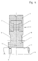
- FIG. 4 reference is made to an embodiment in which the hub ring 1 is provided in the region of its inner circumference with a holding claw 5 which is movable in the radial direction, the holding claw 5 being snapped into a groove 6 of a drive shaft 7 which is used and is open radially outwards.
- the axial fixing of the hub ring 1 on the drive shaft 7 is thereby simplified.
- a further embodiment which is not shown in more detail here, can consist in that in addition to the holding claw which is movable in the radial direction, a hub ring shaft connection is provided which has a polygonal profile or a spline. This ensures additional security in the circumferential direction.
- the support disk according to the invention is characterized by simple production, low manufacturing costs, unbalance phenomena which cannot be determined over the entire speed range and overall by good usage properties.
Landscapes
- Engineering & Computer Science (AREA)
- Mechanical Engineering (AREA)
- Textile Engineering (AREA)
- Mechanical Operated Clutches (AREA)
- Injection Moulding Of Plastics Or The Like (AREA)
- Connection Of Motors, Electrical Generators, Mechanical Devices, And The Like (AREA)
- Spinning Or Twisting Of Yarns (AREA)
Description
- Die Erfindung betrifft eine Stützscheibe nach dem Oberbegriff von Anspruch 1.
- Eine solche Stützscheibe ist aus der US 4,893,947 bekannt. Der Stützring und der Nabenring bestehen jeweils aus polymerem Werkstoff und sind formschlüssig miteinander verbunden. Die formschlüssige Verbindung erfolgt im Bereich des Außenumfangs des Nabenrings, wobei in radialer Richtung hinterschnittene Ausnehmungen des Nabenrings vom Werkstoff des Stützrings vollständig ausgefüllt sind. Der Nabenring besteht aus einem auf Nylon basierenden Thermoplast, der einen Glasfiberanteil von 5 bis 10 Gew.-% aufweist. Der Stützring besteht aus einem flexiblen Elastomer. Der Nabenring ist mit einer zylinderförmigen zentralen Ausnehmung versehen, in der während der bestimmungsgemäßen Verwendung von einer Achse oder Welle durchdrungen ist.
- Aus der US 4,893,946 ist eine weitere Stützscheibe bekannt, deren Stützring aus einem polymeren Werkstoff besteht und formschlüssig mit einem bevorzugt aus metallischem Werkstoff bestehenden Nabenring verbunden ist. Die formschlüssige Verbindung erfolgt dadurch, daß ein in radialer Richtung angeordneter Vorsprung von Nabenring oder Schwungring in einer hinterschnittenen Ausnehmung von Schwungring oder Nabenring angeordnet ist. Die Verbindung kann beispielsweise im Querschnitt betrachtet schwalbenschwanzförmig ausgebildet sein. Der Nabenring weist eine zentrale, zylinderförmige Ausnehmung auf und wird beispielsweise auf eine Auftriebswelle aufgeschrumpft. Besteht der Nabenring aus einem metallischen Werkstoff, ist die Befestigung des Stützringes am Nabenring problematisch. Der Nabenring muß gründlich entfettet und sodann derart behandelt werden, daß der Stützring aus elastomerem Werkstoff am Außenumfang festgelegt und dort während der bestimmungsgemäßen Verwendung zuverlässig gehalten werden kann. In fertigungstechnischer Hinsicht ist die Herstellung eines derartigen Bauteils sehr zeitaufwendig.
- Der Erfindung liegt die Aufgabe zugrunde, eine Stützscheibe der eingangs genannten Art derart weiterzuentwickeln, daß die axiale Positionierung der Stützscheibe auf einer Antriebswelle vereinfacht ist, daß die Stützscheibe einfach, schnell und in wirtschaftlicher Hinsicht kostengünstig herstellbar ist und eine gute Rotationssymmetrie aufweist.
- Diese Aufgabe wird erfindungsgemäß mit den kennzeichnenden Merkmalen von Anspruch 1 gelöst. Auf vorteilhafte Ausgestaltungen nehmen die Unteransprüche Bezug.
- Bei der erfindungsgemäßen Stützscheibe ist es vorgesehen, daß der Nabenring aus einem polymeren Werkstoff besteht, der einen Elastizitätsmodul von 7000 bis 13000 N/mm² aufweist, eine Wärmeformbeständigkeit von 150 bis 250° C sowie eine Bruchdehnung von 1,3 bis 3 % und daß der Nabenring im Bereich seines Innenumfangs mit wenigstens einer in radialer Richtung beweglichen Haltekralle versehen ist und mittels der Haltekralle in einer radial nach außen offenen Nut einer zur Anwendung gelangenden Antriebswelle einschnappbar ist.
- Der Stützring und der Nabenring bilden eine untrennbare Einheit, welche sich problemlos und kostengünstig in großtechnischem Maßstab erzeugen läßt und den vorliegend geforderten Bedingungen in einer ausgezeichneten Weise gerecht wird. Die Einheit zeichnet sich durch eine große Formbeständigkeit aus, was es ermöglicht, im langfristigen Gebrauch eine sichere Festlegung des Nabenringes, beispielsweise auf einer Welle, zu erzielen. Die Verwendung sekundärer Hilfsmittel ist zumeist entbehrlich, und es genügt ein einfaches, axiales Aufpressen des Nabenringes auf die Welle. Im übrigen können selbstverständlich auch aus dem allgemeinen Maschinenbau bekannte Wellen-Nabenverbindungen zur Anwendung gelangen, wie beispielsweise Polygonprofile oder Keilwellenverbindungen.
- Da der Nabenring aus polymerem Werkstoff besteht, ist auch bei der Verwendung einer Welle aus Stahl und aufgepreßtem Nabenring eine Beschädigung des Nabenringes nicht zu befürchten.
- Durch die Verwendung elastomeren Polyurethans für die Herstellung des Stützringes weist dieser eine besonders gute Abriebbeständigkeit in Verbindung mit einem für den Einsatzfall geeigneten Dämpfungsverhalten auf, was die Erzielung einer guten Gebrauchsdauer ermöglicht.
- Um besonderen Gegebenheiten des Anwendungsfalles gerecht zu werden, ist der Nabenring im Bereich seines Innenumfanges mit wenigstens einer in radialer Richtung beweglichen Haltekralle versehen und mittels der Haltekralle in einer nach außen offenen Nut einer zur Anwendung gelangenden Antriebswelle einschnappbar. Die axiale Positionierung der Stützscheibe auf der Antriebswelle ist dadurch besonders einfach.
- Außerdem kann der Nabenring im Bereich seines Innenumfanges zumindest eine quer zur Umfangsrichtung angeordneten Nut aufweisen, die mit zumindest einem Vorsprung der Antriebswelle in Eingriff bringbar ist. Durch diese Ausgestaltung, die beispielsweise auch mit einer Haltekralle kombiniert sein kann, ergibt sich eine zusätzliche Sicherheit gegen eine Verdrehung der Stützscheibe auf der Antriebswelle. Zur Anwendung gelangen bevorzugt Wellen-Nabenverbindungen mit Polygonprofil oder Keilwellenverbindungen.
- Der Nabenring kann im Bereich seiner radial äußeren Begrenzung ein I-förmiges Profil und der Stützring im Bereich seiner radial inneren Begrenzung ein U-förmiges Profil aufweisen, wobei das U-förmige Profil des Stützringes das I-förmige Profil des Nabenringes mit radial nach innen vorstehenden Schenkeln beiderseits umgreift. Die Kontaktfläche des Nabenringes in bezug auf den Stützring erfährt hierdurch eine Vergrößerung, was die Haftung beider Ringe aneinander wesentlich erhöht. Fliehkraftbedingten Deformierungsveränderungen des Stützringes läßt sich hierdurch wirksam begegnen.
- Als zweckmäßig hat es sich erwiesen, wenn die radiale Teilfläche des I-förmigen Profils des Nabenringes von gleichmäßig in Umfangsrichtung verteilten Durchbrechungen durchdrungen ist und wenn die Schenkel des Profils des Stützringes durch die Durchbrechungen hindurch einstückig ineinander übergehend ausgebildet sind. Der Naben- und der Stützring sind durch diese Ausbildung formschlüssig aneinander festgelegt, was auch unter ungünstigen Betriebsbedingungen eine gegenseitige Trennung voneinander so gut wie völlig ausschließt.
- Als günstig in bezug auf die Herstellung von Nabenringen hat sich die Verwendung von Polyharnstoff erwiesen. Dieser weist nicht nur ein Elastizitätsmodul von 7000 bis 13000 N/mm² auf, eine Wärmeformbeständigkeit von 150 bis 250° C und eine Bruchdehnung von 1,3 bis 3 %, sondern darüber hinaus die Eigenschaft hat, dem elastomerem Polyurethan eine gute Haftgrundlage unter Vermeidung aufwendiger Vorbehandlungsmaßnahmen zu bieten. Für die Wirtschaftlichkeit der Herstellung der erfindungsgemäßen Stützscheibe ist das von großem Vorteil.
- Unter Bruchdehnung wird im Rahmen der vorliegenden Erfindung die auf die ursprüngliche Meßlänge des Probekörpers bezogene Längenänderung eines Prüflings zu jedem beliebigen Zeitpunkt verstanden (DIN 53455).
- Unter dem Elastizitätsmodul wird im Rahmen der vorliegenden Erfindung der Zusammenhang zwischen der Spannung und der Dehnung im Falle der Stabdehnung bei ungehinderter Querschnittsverkleinerung verstanden (DIN 53457).
- Unter der Wärmeformbeständigkeit wird im Rahmen der vorliegenden Erfindung die Fähigkeit eines Probekörpers verstanden, unter bestimmter, ruhender Beanspruchung seine Form bis zu einer bestimmten Temperatur weitgehend zu bewahren (DIN 53461).
- Gemäß einer weiteren vorteilhaften Ausgestaltung kann der Nabenring in zumindest einem Teilbereich seiner axialen Begrenzungsflächen einen Signalgeber aufweisen. Bevorzugt, im Hinblick auf die Vermeidung von Unwuchterscheinungen kann der Signalgeber durch eine Licht reflektierende Folie gebildet sein, die adhäsiv auf dem Nabenring festgelegt ist. Durch diese Ausgestaltung kann in besonders einfacher Weise eine Drehzahlüberwachung/-regelung der erfindungsgemäßen Stützscheibe erfolgen. Der Signalaufnehmer kann beispielsweise signalleitend über eine Steuereinrichtung mit dem Antrieb der Stützscheibe verbunden sein. Eine Beeinflussung der Rotationsgeschwindigkeit der Stützscheibe wird hierdurch wesentlich vereinfacht.
- Der Gegenstand der Erfindung wird nachfolgend anhand der als Anlage beigefügten Zeichnung weiter verdeutlicht. Es zeigen:
- Fig. 1
- eine Stützscheibe in der Vorderansicht in teilweise geschnittener Darstellung;
- Fig. 2
- die Stützscheibe gemäß Figur 1 in quergeschnittener Darstellung;
- Fig. 3
- einen Ausschnitt aus der Stützscheibe gemäß Figur 2 in vergrößerter Darstellung;
- Fig. 4
- einen Segmentausschnitt aus einer alternativen Ausführungsform einer Stützscheibe in einer Ansicht von vorn.
- Die in Figur 1 gezeigte Stützscheibe ist für den Rotor einer Offenendspinnmaschine bestimmt, der Drehzahlen im Bereich von 130.000/min erreichen kann.
- Die Stützscheibe besteht aus einem Nabenring 1 aus polymerem Werkstoff, der von rotationssymmetrischer Gestalt ist und in radialer Richtung außenseitig ein I-förmiges Profil aufweist.
- Der Nabenring 1 besteht in diesem Beispiel aus Polyharnstoff und weist einen Elastizitätsmodul von 10000 N/mm² auf, eine Wärmeformbeständigkeit von 200° C und eine Bruchdehnung von 2,5 %.
- Der Nabenring 1 ist der Rotationsachse 9 der Stützscheibe im wesentlichen senkrecht zugeordnet. Er ist im mittleren Bereich seines I-förmigen Profils, innerhalb der radialen Erstreckung von gleichmäßig in Umfangsrichtung verteilten Durchbrechungen 4, in diesem speziellen Fall in Form von Bohrungen, axial durchdrungen (Figuren 1, 3, 4).
- Der Stützring 3 besteht aus elastomerem Polyurethan, welches unmittelbar an den Nabenring 1 angeformt ist. Der Stützring 3 hat ein im wesentlichen U-förmiges Profil, welches das I-förmige Profil des Nabenringes 1 mit radial nach innen vorstehenden Schenkeln 2 umschließt.
- Die Schenkel 2 sind dabei durch die Durchbrechungen 4 des Nabenringes 1 hindurch ineinander übergehend verbunden, wodurch der Stützring 3 nicht nur in adhäsiver Weise an dem Nabenring 1 festgelegt ist, sondern zusätzlich aufgrund einer gegenseitigen, formschlüssigen Umschließung bzw. Durchdringung der Profile (Figur 1, Figur 3). Auch bei höchsten Drehzahlen ist hierdurch eine fliehkraftbedingte Ablösung des Stützringes 3 von dem Nabenring 1 nicht zu befürchten.
- In Figur 4 ist bezug genommen auf eine Ausführung, bei der der Nabenring 1 im Bereich seines Innenumfanges mit einer in radialer Richtung beweglichen Haltekralle 5 versehen ist, wobei die Haltekralle 5 in einer radial nach außen offenen Nut 6 einer zur Anwendung gelangenden Antriebswelle 7 eingeschnappt ist. Die axiale Festlegung des Nabenringes 1 auf der Antriebswelle 7 ist dadurch vereinfacht.
- Eine weitere Ausgestaltung, die hier nicht näher gezeigt ist, kann darin bestehen, daß zusätzlich zu der in radialer Richtung beweglichen Haltekralle eine Nabenring-Wellenverbindung vorgesehen ist, die ein polygonförmiges Profil oder eine Keilverzahnung aufweist. Eine zusätzliche Sicherung in Umfangsrichtung ist dadurch gewährleistet.
- Neben einer besonders guten, rotationssymmetrischen Festlegung des Stützringes 3 auf dem Nabenring 1 zeichnet sich die erfindungsgemäße Stützscheibe durch einfache Produktion, geringe Herstellungskosten, nicht feststellbare Unwuchterscheinungen über den gesamten Drehzahlbereich und insgesamt durch gute Gebrauchseigenschaften aus.
Claims (8)
- Stützscheibe für einen Rotor einer Offenendspinnmaschine, umfassend einen Nabenring (1) und einen auf dessen Außenumfang festgelegten Stützring (3) aus elastomerem Material, wobei der Nabenring (1) aus einem polymeren Werkstoff besteht, dadurch gekennzeichnet, daß der Nabenring (1) aus einem polymeren Werkstoff besteht, der einen Elastizitätsmodul von 7000 bis 13000 N/mm² aufweist, eine Wärmeformbeständigkeit von 150 bis 250° C sowie eine Bruchdehnung von 1,3 bis 3 % und daß der Nabenring (1) im Bereich seines Innenumfangs mit wenigstens einer in radialer Richtung beweglichen Haltekralle (5) versehen ist und mittels der Haltekralle (5) in einer radial nach außen offenen Nut (6) einer zur Anwendung gelangenden Antriebswelle (7) einschnappbar ist.
- Stützscheibe nach Anspruch 1, dadurch gekennzeichnet, daß der Nabenring (1) im Bereich seines Innenumfanges zumindest eine quer zur Umfangsrichtung angeordneten Nut aufweist, die mit zumindest einem Vorsprung der Antriebswelle (7) in Eingriff bringbar ist.
- Stützscheibe nach Anspruch 1 bis 2, dadurch gekennzeichnet, daß der Nabenring (1) im Bereich seiner radial äußeren Begrenzung ein I-förmiges Profil aufweist, daß der Stützring (3) ein U-förmiges Profil aufweist und daß das U-förmige Profil des Stützringes (3) das I-förmige Profil des Nabenringes (1) mit radial nach innen vorstehenden Schenkeln (2) beiderseits umgreift.
- Stützscheibe nach Anspruch 3, dadurch gekennzeichnet, daß das I-Profil des Nabenringes (1) von gleichmäßig in Umfangsrichtung verteilten Durchbrechungen (4) durchdrungen ist und daß die Schenkel (2) des U-förmigen Profils des Stützringes (3) durch die Durchbrechungen (4) hindurch einstückig ineinander übergehend ausgebildet sind.
- Stützscheibe nach Anspruch 1 bis 4, dadurch gekennzeichnet, daß der Nabenring (1) aus Polyharnstoff besteht.
- Stützscheibe nach Anspruch 1 bis 4, dadurch gekennzeichnet, daß der Nabenring (1) aus duroplastischem Polyurethan besteht.
- Stützscheibe nach Anspruch 1 bis 6, dadurch gekennzeichnet, daß der Nabenring (1) in zumindest einem Teilbereich seiner axialen Begrenzungsflächen (10) einen Signalgeber aufweist.
- Stützscheibe nach Anspruch 7, dadurch gekennzeichnet, daß der Signalgeber durch eine Licht reflektierende Folie gebildet ist und daß die Folie adhäsiv auf dem Nabenring (1) festgelegt ist.
Applications Claiming Priority (2)
| Application Number | Priority Date | Filing Date | Title |
|---|---|---|---|
| DE4136793A DE4136793C1 (de) | 1991-11-08 | 1991-11-08 | |
| DE4136793 | 1991-11-08 |
Publications (2)
| Publication Number | Publication Date |
|---|---|
| EP0540818A1 EP0540818A1 (de) | 1993-05-12 |
| EP0540818B1 true EP0540818B1 (de) | 1995-09-27 |
Family
ID=6444365
Family Applications (1)
| Application Number | Title | Priority Date | Filing Date |
|---|---|---|---|
| EP92110026A Expired - Lifetime EP0540818B1 (de) | 1991-11-08 | 1992-06-15 | Stützscheibe |
Country Status (6)
| Country | Link |
|---|---|
| US (1) | US5362160A (de) |
| EP (1) | EP0540818B1 (de) |
| DE (2) | DE4136793C1 (de) |
| ES (1) | ES2078591T3 (de) |
| GR (1) | GR3018264T3 (de) |
| TR (1) | TR26381A (de) |
Families Citing this family (14)
| Publication number | Priority date | Publication date | Assignee | Title |
|---|---|---|---|---|
| DE19511000C2 (de) * | 1995-03-25 | 1998-10-22 | Freudenberg Carl Fa | Stützscheibe |
| US5675964A (en) * | 1993-04-27 | 1997-10-14 | Fritz Stahlecker | Open end spinning supporting disk with asymmetric magnetic rotational speed indicator |
| DE4334985B4 (de) * | 1993-10-14 | 2005-12-29 | Stahlecker, Fritz | Stützscheibe für eine Stützscheibenlagerung eines OE-Spinnrotors und Verfahren zur Herstellung dieser Stützscheibe |
| DE4437182C1 (de) * | 1994-10-18 | 1995-11-02 | Freudenberg Carl Fa | Laufscheibe für eine Textilmaschine, insbesondere Spinnmaschine |
| DE19549466C2 (de) * | 1995-03-25 | 1999-10-14 | Rieter Ingolstadt Spinnerei | Stützscheibe |
| DE19712916A1 (de) * | 1997-03-27 | 1998-10-01 | Novibra Gmbh | Stützscheibe für eine Stützscheibenlagerung von OE-Spinnrotoren |
| DE19756711C2 (de) * | 1997-12-19 | 2001-07-19 | Schlafhorst & Co W | Stützscheibenlagerung für einen Offenend-Spinnrotor |
| DE19804868C2 (de) * | 1998-02-09 | 2000-06-21 | Freudenberg Carl Fa | Stützscheibe |
| DE29806031U1 (de) * | 1998-04-02 | 1998-06-25 | Legrom, Friedrich, 71540 Murrhardt | Seitenscheibe für Stützscheibenlagerung einer Rotorspinnmaschine |
| DE19908922B4 (de) * | 1999-03-02 | 2007-04-19 | Carl Freudenberg Kg | Stützscheibe für die Lagerung eines Rotors |
| DE10039121B4 (de) * | 2000-08-07 | 2007-04-12 | Carl Freudenberg Kg | Stützscheibe für die Lagerung eines Rotors |
| GB0222480D0 (en) | 2002-09-27 | 2002-11-06 | Ricardo Consulting Eng | Torsionally damped rotary shafts |
| US7073474B2 (en) * | 2003-11-06 | 2006-07-11 | Brp Us Inc. | Flywheel with torsional dampening ring |
| ATE383463T1 (de) | 2005-11-22 | 2008-01-15 | Freudenberg Carl Kg | Schützscheibe |
Family Cites Families (8)
| Publication number | Priority date | Publication date | Assignee | Title |
|---|---|---|---|---|
| DE3615777A1 (de) * | 1986-05-10 | 1987-11-12 | Stahlecker Fritz | Stuetzscheibe fuer eine stuetzscheibenlagerung eines oe-spinnrotors |
| DE3630257C2 (de) * | 1986-09-05 | 1995-10-12 | Schlafhorst & Co W | Stützscheibe für die Rotorwelle einer OE-Spinnmaschine |
| DE3719445A1 (de) * | 1987-06-11 | 1988-12-22 | Fritz Stahlecker | Stuetzscheibe fuer eine stuetzscheibenlagerung |
| US4893947A (en) * | 1989-01-23 | 1990-01-16 | Hurley Robert E | Spinning machine rotor shaft disk |
| US4893946A (en) * | 1989-05-15 | 1990-01-16 | Amkor Industries, Inc. | Roller for spinning frame |
| DE4011632A1 (de) * | 1990-04-11 | 1991-10-17 | Fritz Stahlecker | Stuetzscheibe fuer eine stuetzscheibenlagerung |
| DE4019028A1 (de) * | 1990-06-14 | 1991-12-19 | Schurr Stahlecker & Grill | Stuetzscheibe fuer eine stuetzscheibenlagerung fuer oe-spinnrotoren und verfahren zu ihrer herstellung |
| DE4136794A1 (de) * | 1991-11-08 | 1993-05-19 | Freudenberg Carl Fa | Stuetzscheibe |
-
1991
- 1991-11-08 DE DE4136793A patent/DE4136793C1/de not_active Expired - Lifetime
-
1992
- 1992-06-15 ES ES92110026T patent/ES2078591T3/es not_active Expired - Lifetime
- 1992-06-15 DE DE59203830T patent/DE59203830D1/de not_active Expired - Lifetime
- 1992-06-15 EP EP92110026A patent/EP0540818B1/de not_active Expired - Lifetime
- 1992-08-24 US US07/934,141 patent/US5362160A/en not_active Expired - Fee Related
- 1992-09-04 TR TR92/0872A patent/TR26381A/xx unknown
-
1995
- 1995-11-30 GR GR950403381T patent/GR3018264T3/el unknown
Also Published As
| Publication number | Publication date |
|---|---|
| TR26381A (tr) | 1995-03-15 |
| DE59203830D1 (de) | 1995-11-02 |
| ES2078591T3 (es) | 1995-12-16 |
| EP0540818A1 (de) | 1993-05-12 |
| GR3018264T3 (en) | 1996-02-29 |
| US5362160A (en) | 1994-11-08 |
| DE4136793C1 (de) | 1993-06-03 |
Similar Documents
| Publication | Publication Date | Title |
|---|---|---|
| EP0540818B1 (de) | Stützscheibe | |
| DE69929554T2 (de) | Lagervorrichtung mit sphärischen Lagerflächen | |
| DE19733478B4 (de) | Schwingungsdämpfer für eine rohrförmige Gelenkwelle | |
| DE19749761A1 (de) | Entkoppelte Riemenscheibe | |
| EP0266479B1 (de) | Torsionsschwingungsdämpfer mit integriertem Schrumpfring | |
| EP0349702A2 (de) | Kühlwasserpumpe mit Riemenantrieb | |
| EP0640746A1 (de) | Rotorgehäuse, insbesondere Gehäuse für Turbotriebwerke | |
| EP0541898B1 (de) | Stützscheibe | |
| DE19736333C1 (de) | Befestigung eines Laufrades einer Strömungsmaschine an einer Welle | |
| EP1146152B1 (de) | Stützscheibe mit Kautschukbelag für eine Stützscheibenlagerung für Spinnrotoren | |
| DE102009048295A1 (de) | Offenend-Spinnrotor | |
| WO1999051802A1 (de) | Ring für ringspinn- und ringzwirnmaschinen | |
| DE4443103B4 (de) | Reibfläche einer für den Einsatz in einer Riemenspanneinrichtung vorgesehenen Reibscheibe | |
| WO2005019670A1 (de) | Magnetisches lagerelement | |
| DE19756711C2 (de) | Stützscheibenlagerung für einen Offenend-Spinnrotor | |
| DE3716588C2 (de) | ||
| DE4437182C1 (de) | Laufscheibe für eine Textilmaschine, insbesondere Spinnmaschine | |
| EP0661476B1 (de) | Torsionsschwingungstilger | |
| EP1719928A2 (de) | Axialsicherungsanordnung für eine Lagerbüchse bei einem Kreuzgelenk | |
| DE4137113B4 (de) | Drehschwingungsdämpfer, insbesondere für Kraftfahrzeugkupplungsscheiben | |
| EP0985838B1 (de) | Stützlager und Verfahren zu seiner Herstellung | |
| DE19511000C1 (de) | Stützscheibe | |
| DE4310978A1 (de) | Bauelement, bestehend aus Reibbelägen mit einer elastischen Zwischenschicht | |
| DE60119460T2 (de) | Elastisches, schwingungsdämpfendes Lager und Verfahren zur Definierung von dessen Eigenschaften | |
| EP0952365A1 (de) | Elastische Wellenkupplung, insbes. hochdrehelastische Vorschaltkupplung für Kardanwellen |
Legal Events
| Date | Code | Title | Description |
|---|---|---|---|
| PUAI | Public reference made under article 153(3) epc to a published international application that has entered the european phase |
Free format text: ORIGINAL CODE: 0009012 |
|
| 17P | Request for examination filed |
Effective date: 19930305 |
|
| AK | Designated contracting states |
Kind code of ref document: A1 Designated state(s): CH DE ES FR GB GR IT LI PT |
|
| 17Q | First examination report despatched |
Effective date: 19940509 |
|
| RAP3 | Party data changed (applicant data changed or rights of an application transferred) |
Owner name: FIRMA CARL FREUDENBERG |
|
| GRAA | (expected) grant |
Free format text: ORIGINAL CODE: 0009210 |
|
| AK | Designated contracting states |
Kind code of ref document: B1 Designated state(s): CH DE ES FR GB GR IT LI PT |
|
| REF | Corresponds to: |
Ref document number: 59203830 Country of ref document: DE Date of ref document: 19951102 |
|
| ITF | It: translation for a ep patent filed | ||
| ET | Fr: translation filed | ||
| GBT | Gb: translation of ep patent filed (gb section 77(6)(a)/1977) |
Effective date: 19951024 |
|
| REG | Reference to a national code |
Ref country code: ES Ref legal event code: FG2A Ref document number: 2078591 Country of ref document: ES Kind code of ref document: T3 |
|
| REG | Reference to a national code |
Ref country code: GR Ref legal event code: FG4A Free format text: 3018264 |
|
| SC4A | Pt: translation is available |
Free format text: 951122 AVAILABILITY OF NATIONAL TRANSLATION |
|
| PLBE | No opposition filed within time limit |
Free format text: ORIGINAL CODE: 0009261 |
|
| STAA | Information on the status of an ep patent application or granted ep patent |
Free format text: STATUS: NO OPPOSITION FILED WITHIN TIME LIMIT |
|
| 26N | No opposition filed | ||
| REG | Reference to a national code |
Ref country code: GB Ref legal event code: IF02 |
|
| PGFP | Annual fee paid to national office [announced via postgrant information from national office to epo] |
Ref country code: PT Payment date: 20040526 Year of fee payment: 13 |
|
| PGFP | Annual fee paid to national office [announced via postgrant information from national office to epo] |
Ref country code: GR Payment date: 20040527 Year of fee payment: 13 |
|
| PGFP | Annual fee paid to national office [announced via postgrant information from national office to epo] |
Ref country code: GB Payment date: 20040528 Year of fee payment: 13 |
|
| PGFP | Annual fee paid to national office [announced via postgrant information from national office to epo] |
Ref country code: ES Payment date: 20040603 Year of fee payment: 13 |
|
| PGFP | Annual fee paid to national office [announced via postgrant information from national office to epo] |
Ref country code: FR Payment date: 20040618 Year of fee payment: 13 |
|
| PG25 | Lapsed in a contracting state [announced via postgrant information from national office to epo] |
Ref country code: GB Free format text: LAPSE BECAUSE OF NON-PAYMENT OF DUE FEES Effective date: 20050615 |
|
| PG25 | Lapsed in a contracting state [announced via postgrant information from national office to epo] |
Ref country code: ES Free format text: LAPSE BECAUSE OF NON-PAYMENT OF DUE FEES Effective date: 20050616 |
|
| PG25 | Lapsed in a contracting state [announced via postgrant information from national office to epo] |
Ref country code: PT Free format text: LAPSE BECAUSE OF NON-PAYMENT OF DUE FEES Effective date: 20051215 |
|
| PG25 | Lapsed in a contracting state [announced via postgrant information from national office to epo] |
Ref country code: GR Free format text: LAPSE BECAUSE OF NON-PAYMENT OF DUE FEES Effective date: 20060103 |
|
| PG25 | Lapsed in a contracting state [announced via postgrant information from national office to epo] |
Ref country code: FR Free format text: LAPSE BECAUSE OF NON-PAYMENT OF DUE FEES Effective date: 20060228 |
|
| GBPC | Gb: european patent ceased through non-payment of renewal fee |
Effective date: 20050615 |
|
| REG | Reference to a national code |
Ref country code: FR Ref legal event code: ST Effective date: 20060228 |
|
| REG | Reference to a national code |
Ref country code: ES Ref legal event code: FD2A Effective date: 20050616 |
|
| PGFP | Annual fee paid to national office [announced via postgrant information from national office to epo] |
Ref country code: CH Payment date: 20110627 Year of fee payment: 20 |
|
| PGFP | Annual fee paid to national office [announced via postgrant information from national office to epo] |
Ref country code: IT Payment date: 20110620 Year of fee payment: 20 |
|
| PGFP | Annual fee paid to national office [announced via postgrant information from national office to epo] |
Ref country code: DE Payment date: 20110704 Year of fee payment: 20 |
|
| REG | Reference to a national code |
Ref country code: DE Ref legal event code: R071 Ref document number: 59203830 Country of ref document: DE |
|
| REG | Reference to a national code |
Ref country code: DE Ref legal event code: R071 Ref document number: 59203830 Country of ref document: DE |
|
| REG | Reference to a national code |
Ref country code: CH Ref legal event code: PL |
|
| PG25 | Lapsed in a contracting state [announced via postgrant information from national office to epo] |
Ref country code: DE Free format text: LAPSE BECAUSE OF EXPIRATION OF PROTECTION Effective date: 20120616 |