EP0540822A1 - Interface simple pour lecteur code-à-barre - Google Patents
Interface simple pour lecteur code-à-barre Download PDFInfo
- Publication number
- EP0540822A1 EP0540822A1 EP92111284A EP92111284A EP0540822A1 EP 0540822 A1 EP0540822 A1 EP 0540822A1 EP 92111284 A EP92111284 A EP 92111284A EP 92111284 A EP92111284 A EP 92111284A EP 0540822 A1 EP0540822 A1 EP 0540822A1
- Authority
- EP
- European Patent Office
- Prior art keywords
- input
- transistor
- signals
- output
- reader
- Prior art date
- Legal status (The legal status is an assumption and is not a legal conclusion. Google has not performed a legal analysis and makes no representation as to the accuracy of the status listed.)
- Withdrawn
Links
Images


Classifications
-
- G—PHYSICS
- G06—COMPUTING OR CALCULATING; COUNTING
- G06K—GRAPHICAL DATA READING; PRESENTATION OF DATA; RECORD CARRIERS; HANDLING RECORD CARRIERS
- G06K7/00—Methods or arrangements for sensing record carriers, e.g. for reading patterns
- G06K7/10—Methods or arrangements for sensing record carriers, e.g. for reading patterns by electromagnetic radiation, e.g. optical sensing; by corpuscular radiation
- G06K7/10544—Methods or arrangements for sensing record carriers, e.g. for reading patterns by electromagnetic radiation, e.g. optical sensing; by corpuscular radiation by scanning of the records by radiation in the optical part of the electromagnetic spectrum
- G06K7/10821—Methods or arrangements for sensing record carriers, e.g. for reading patterns by electromagnetic radiation, e.g. optical sensing; by corpuscular radiation by scanning of the records by radiation in the optical part of the electromagnetic spectrum further details of bar or optical code scanning devices
- G06K7/10851—Circuits for pulse shaping, amplifying, eliminating noise signals, checking the function of the sensing device
-
- G—PHYSICS
- G06—COMPUTING OR CALCULATING; COUNTING
- G06K—GRAPHICAL DATA READING; PRESENTATION OF DATA; RECORD CARRIERS; HANDLING RECORD CARRIERS
- G06K17/00—Methods or arrangements for effecting co-operative working between equipments covered by two or more of main groups G06K1/00 - G06K15/00, e.g. automatic card files incorporating conveying and reading operations
- G06K17/0022—Methods or arrangements for effecting co-operative working between equipments covered by two or more of main groups G06K1/00 - G06K15/00, e.g. automatic card files incorporating conveying and reading operations arrangements or provisions for transferring data to distant stations, e.g. from a sensing device
Definitions
- the present invention relates to interface circuits for use in digital bar code readers.
- bar code readers customarily employ a multiplicity of jacks. Each provides for a different jack or connector which provides a receptacle for a plug from a different Input/Output (“I/O") device, such as computers, displays, printers and even other bar code readers.
- I/O Input/Output
- a separate jack and plug is used for a battery charger when the reader is portable and uses a rechargeable battery.
- a multiplicity of ports present several problems. First, a relatively large amount of space is needed to accommodate all of the jacks, necessarily resulting in larger bar code readers--an undesirable condition for hand-held instruments. Second, separate connecting cables and plugs are needed to carry each signal, which makes the use of a hand-held reader cumbersome.
- each of a plurality of jacks provides an entrance for the introduction of dirt and other foreign objects into the interior of the reader.
- switches which multiplex the reader to the I/O devices and the battery charger. Circuits for controlling the switches increase the complexity and cost of the bar code reader.
- Another object of the invention is to provide a unitary interface circuit in an instrument such as a bar code reader, which enables the use of a single terminal to provide connections from I/O devices and a battery charger, and which obviates the problems discussed above.
- the invention as embodied is an optical bar code reader including an interface circuit internal of the reader connected to the unitary terminal of the reader.
- the interface circuit includes output means for applying signals generated by the reader to I/O devices external of the reader.
- the interface also includes input means for operating on digital electrical information signals generated externally of the reader for applying these signals to the reader.
- the interface includes battery charging current means for passing current of sufficient magnitude to charge the reader's internal rechargeable battery.
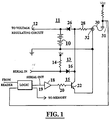
- the upper section 11 of FIG. 1 is the means by which battery charging current is passed through the interface.
- Diode 26 allows charging current to flow to the reader's internal rechargeable battery 10 from an external power supply while simultaneously preventing the discharge of the battery 10 through the same path.
- Terminal 12 may be attached to a voltage regulating circuit to ensure that the proper voltage is always provided from the battery 10 to active circuitry in the reader.
- Resistor 28 limits the flow of current to a desirable rate for charging the internal battery. This shown for "charging" in FIG. 2.
- the middle section 13 of FIG. 1 provides means by which electrical signals generated externally of the reader are delivered to the reader.
- This input circuit allows electrical data signals from an I/O device to flow to the reader via an electrically conductive cable.
- This capability is useful, for instance, when a multiplicity of scanners are to be synchronized under the same operational scheme. For example, signals describing the number of bar code characters to be recognized and the left or right handedness of the operator can be input to a reader simply by passing those signals through the interface circuit.
- my U.S. patent application serial no. 07/ for further information concerning a hand-held bar code print quality measuring and display instrument which uses left and right handedness control signals to flip-over its display to accommodate use of the instrument either in the left or right hand of the operator.
- diode 16 causes a low potential to appear at the anode thereof whenever the voltage at the input-output terminal is pulled low.
- resistor 14 pulls down the serial in 17 potential to a value equal to the sum of the terminal 32 potential and the voltage drop across diode 16.
- the potential at the anode of diode 16 likewise is high, that is, the potential at the anode of diode 16 is greater than the potential at terminal 32 by the drop across the diode 16.
- the lower section 15 of FIG. 1 is the signal output circuitry of the interface.
- the normally high potential at the logic inverter 18 is reduced, resulting in a corresponding rise in the output signal level of logic inverter 18. This is shown for a "serial out" stream of data signal pulses in FIG. 2.
- Resistor 20 protects transistor 22 by limiting base current flow.
- the resulting high potential sensed at the base of transistor 22 causes transistor 22 to conduct, allowing current to flow from collector to emitter.
- the current path from collector to emitter directs the current flowing into the input-output terminal 32 to ground. Consequently, the voltage across input-output terminal 32 is reduced.
- the duration of the changes in the terminal 32 potential defines the information contained in the reader's output signals.
- Switch 30 allows serial out data to be stored internally of the reader in the event that no plug is received in terminal 32.
- switch 30 grounds plug detect line 31. This causes a low signal to be detected by the reader's internal plug detect circuitry, and serial out information is stored in the reader's internal memory.
- switch 30 opens causing the input to the plug detect circuit to be pulled high, and serial out signals are not stored in the reader's internal memory.
- FIG. 3 shows the adapter which is situated externally of the scanner.
- the purpose of the adapter is to direct various signals to or from the scanner through the uniport interface terminal 32, for application to the uniport interface of the reader.
- the DC power shown at 58 (+12v) for the adapter is supplied by the I/O device.
- the voltage across plug 42 is high because of the high impedance of the interface.
- the potential at the junction of resistors 44 and 48 will be high.
- This high potential at the base of transistor 50 causes transistor 50 to conduct current from collector to emitter.
- the current through the collector and emitter flows to ground.
- transistor 46 acts to pull down the voltage sensed at the collector of transistor 50, supplying a low voltage signal to the I/O device.
- the voltage across plug 42 is reduced to a low level.
- the reduced potential is sensed at the base of transistor 50, and causes transistor 50 to turn off. That is, transistor 50 will no longer conduct from collector to emitter. This results in an increased voltage at the collector of transistor 50 and a consequent higher input potential to the I/O device.
- transistor 50 When the signal pulse from the interface returns to its steady state level, transistor 50 again conducts, pulling the collector voltage to its lower, steady state level.
- the normally low signal level at 62 is raised to a high level.
- Resistor 54 protects transistor 52 by limiting its base current. This high value is sensed by the base of transistor 52, causing transistor 52 to conduct current from collector to emitter. This path through transistor 52 is connected to ground. The voltage at the collector of transistor 52 is thereby pulled down to a low level with a consequent reduction in voltage across plug 42.
- Diode 56 acts as a snubbing diode to protect transistor 52 in the event that the voltage at point 62 drops to a negative level.
- FIG. 4 shows a second adapter which simultaneously directs battery charging and input/output signals to and from the reader.
- battery charging current from an external battery charging circuit like the one shown in FIG. 5 enters the adapter at plug 64. This charging current flows through inductor 68 to plug 76, and into the battery charging, upper section 11 of the interface circuit of FIG. 1.
- Transistor 70 therefore turns off, returning the base potential of transistor 74 to a low value, which turns transistor 74 off.
- transistor 74 is turned off, the potential at point 86 is returned to a low level, and battery charging recommences.
- Diode 66 acts as a snubbing diode to limit the base-emitter voltage of transistor 70 in the event that the potential at jack 64 is reduced to a value below the potential at plug 76.
- Diode 82 acts as a snubbing diode to protect transistor 80 in the event that the voltage at point 88 drops to a negative level.
- FIG. 5 shows a battery charging circuit which may be used with the uniport interface circuit.
- the circuit consists of a transformer, the primary 40 of which is supplied with 110 VAC power.
- the secondary is a half-wave rectification circuit consisting of a diode 38, a capacitor 36 and an output plug 34.
- the circuit acts to rectify the AC signal induced at the secondary 38 and supply a DC charging signal to the interface.
Landscapes
- Engineering & Computer Science (AREA)
- Physics & Mathematics (AREA)
- Electromagnetism (AREA)
- General Physics & Mathematics (AREA)
- Theoretical Computer Science (AREA)
- Health & Medical Sciences (AREA)
- General Engineering & Computer Science (AREA)
- General Health & Medical Sciences (AREA)
- Toxicology (AREA)
- Artificial Intelligence (AREA)
- Computer Vision & Pattern Recognition (AREA)
- Charge And Discharge Circuits For Batteries Or The Like (AREA)
- Power Sources (AREA)
Applications Claiming Priority (2)
| Application Number | Priority Date | Filing Date | Title |
|---|---|---|---|
| US07/785,849 US5233169A (en) | 1991-10-31 | 1991-10-31 | Uniport interface for a bar code reading instrument |
| US785849 | 2001-02-16 |
Publications (1)
| Publication Number | Publication Date |
|---|---|
| EP0540822A1 true EP0540822A1 (fr) | 1993-05-12 |
Family
ID=25136813
Family Applications (1)
| Application Number | Title | Priority Date | Filing Date |
|---|---|---|---|
| EP92111284A Withdrawn EP0540822A1 (fr) | 1991-10-31 | 1992-07-03 | Interface simple pour lecteur code-à-barre |
Country Status (3)
| Country | Link |
|---|---|
| US (1) | US5233169A (fr) |
| EP (1) | EP0540822A1 (fr) |
| JP (1) | JPH08227438A (fr) |
Families Citing this family (29)
| Publication number | Priority date | Publication date | Assignee | Title |
|---|---|---|---|---|
| US6631842B1 (en) | 2000-06-07 | 2003-10-14 | Metrologic Instruments, Inc. | Method of and system for producing images of objects using planar laser illumination beams and image detection arrays |
| US7387253B1 (en) | 1996-09-03 | 2008-06-17 | Hand Held Products, Inc. | Optical reader system comprising local host processor and optical reader |
| US5578834A (en) * | 1994-06-21 | 1996-11-26 | Tracker Technologies, Inc. | Electrical/optical interface coupler |
| US6629641B2 (en) | 2000-06-07 | 2003-10-07 | Metrologic Instruments, Inc. | Method of and system for producing images of objects using planar laser illumination beams and image detection arrays |
| US7028899B2 (en) | 1999-06-07 | 2006-04-18 | Metrologic Instruments, Inc. | Method of speckle-noise pattern reduction and apparatus therefore based on reducing the temporal-coherence of the planar laser illumination beam before it illuminates the target object by applying temporal phase modulation techniques during the transmission of the plib towards the target |
| US7010501B1 (en) * | 1998-05-29 | 2006-03-07 | Symbol Technologies, Inc. | Personal shopping system |
| US7162636B2 (en) | 1998-06-22 | 2007-01-09 | Semtek Innovative Solutions, Inc. | Method and apparatus for securing and authenticating encoded data and documents containing such data |
| US7708205B2 (en) | 2003-11-13 | 2010-05-04 | Metrologic Instruments, Inc. | Digital image capture and processing system employing multi-layer software-based system architecture permitting modification and/or extension of system features and functions by way of third party code plug-ins |
| US7607581B2 (en) | 2003-11-13 | 2009-10-27 | Metrologic Instruments, Inc. | Digital imaging-based code symbol reading system permitting modification of system features and functionalities |
| US7540424B2 (en) | 2000-11-24 | 2009-06-02 | Metrologic Instruments, Inc. | Compact bar code symbol reading system employing a complex of coplanar illumination and imaging stations for omni-directional imaging of objects within a 3D imaging volume |
| US7464877B2 (en) | 2003-11-13 | 2008-12-16 | Metrologic Instruments, Inc. | Digital imaging-based bar code symbol reading system employing image cropping pattern generator and automatic cropped image processor |
| US8042740B2 (en) | 2000-11-24 | 2011-10-25 | Metrologic Instruments, Inc. | Method of reading bar code symbols on objects at a point-of-sale station by passing said objects through a complex of stationary coplanar illumination and imaging planes projected into a 3D imaging volume |
| US7128266B2 (en) | 2003-11-13 | 2006-10-31 | Metrologic Instruments. Inc. | Hand-supportable digital imaging-based bar code symbol reader supporting narrow-area and wide-area modes of illumination and image capture |
| US7490774B2 (en) | 2003-11-13 | 2009-02-17 | Metrologic Instruments, Inc. | Hand-supportable imaging based bar code symbol reader employing automatic light exposure measurement and illumination control subsystem integrated therein |
| US7594609B2 (en) | 2003-11-13 | 2009-09-29 | Metrologic Instruments, Inc. | Automatic digital video image capture and processing system supporting image-processing based code symbol reading during a pass-through mode of system operation at a retail point of sale (POS) station |
| DE10126154B4 (de) * | 2001-05-30 | 2005-10-06 | Leuze Electronic Gmbh & Co Kg | Optoelektronische Vorrichtung |
| US7513428B2 (en) | 2001-11-21 | 2009-04-07 | Metrologic Instruments, Inc. | Planar laser illumination and imaging device employing laser current modulation to generate spectral components and reduce temporal coherence of laser beam, so as to achieve a reduction in speckle-pattern noise during time-averaged detection of images of objects illuminated thereby during imaging operations |
| US7430674B2 (en) * | 2002-02-12 | 2008-09-30 | Semtek Innovative Solutions, Inc. | Magnetic stripe reader with power management control for attachment to a PDA device |
| US7841533B2 (en) | 2003-11-13 | 2010-11-30 | Metrologic Instruments, Inc. | Method of capturing and processing digital images of an object within the field of view (FOV) of a hand-supportable digitial image capture and processing system |
| US7364081B2 (en) * | 2003-12-02 | 2008-04-29 | Hand Held Products, Inc. | Method and apparatus for reading under sampled bar code symbols |
| US7506812B2 (en) | 2004-09-07 | 2009-03-24 | Semtek Innovative Solutions Corporation | Transparently securing data for transmission on financial networks |
| US9123042B2 (en) * | 2006-10-17 | 2015-09-01 | Verifone, Inc. | Pin block replacement |
| US9361617B2 (en) | 2008-06-17 | 2016-06-07 | Verifone, Inc. | Variable-length cipher system and method |
| US8769275B2 (en) | 2006-10-17 | 2014-07-01 | Verifone, Inc. | Batch settlement transactions system and method |
| US20080288403A1 (en) * | 2007-05-18 | 2008-11-20 | Clay Von Mueller | Pin encryption device security |
| US8355982B2 (en) | 2007-08-16 | 2013-01-15 | Verifone, Inc. | Metrics systems and methods for token transactions |
| US8144940B2 (en) | 2008-08-07 | 2012-03-27 | Clay Von Mueller | System and method for authentication of data |
| US8251283B1 (en) | 2009-05-08 | 2012-08-28 | Oberon Labs, LLC | Token authentication using spatial characteristics |
| US8392260B2 (en) | 2010-08-30 | 2013-03-05 | Hand Held Products, Inc. | Short-charge cordless scanner for retail terminals |
Citations (2)
| Publication number | Priority date | Publication date | Assignee | Title |
|---|---|---|---|---|
| EP0217665A2 (fr) * | 1985-10-02 | 1987-04-08 | Videx, Inc. | Lecteur de code optique portatif et programmable |
| US4945216A (en) * | 1985-11-06 | 1990-07-31 | Sharp Kabushiki Kaisha | Wireless bar code reader |
Family Cites Families (2)
| Publication number | Priority date | Publication date | Assignee | Title |
|---|---|---|---|---|
| US4970379A (en) * | 1987-04-30 | 1990-11-13 | Norand Corporation | Bar code scanner system and scanner circuitry therefor |
| US5055660A (en) * | 1988-06-16 | 1991-10-08 | Avicom International, Inc. | Portable transaction monitoring unit for transaction monitoring and security control systems |
-
1991
- 1991-10-31 US US07/785,849 patent/US5233169A/en not_active Expired - Fee Related
-
1992
- 1992-07-03 EP EP92111284A patent/EP0540822A1/fr not_active Withdrawn
- 1992-10-30 JP JP4315868A patent/JPH08227438A/ja not_active Withdrawn
Patent Citations (2)
| Publication number | Priority date | Publication date | Assignee | Title |
|---|---|---|---|---|
| EP0217665A2 (fr) * | 1985-10-02 | 1987-04-08 | Videx, Inc. | Lecteur de code optique portatif et programmable |
| US4945216A (en) * | 1985-11-06 | 1990-07-31 | Sharp Kabushiki Kaisha | Wireless bar code reader |
Also Published As
| Publication number | Publication date |
|---|---|
| JPH08227438A (ja) | 1996-09-03 |
| US5233169A (en) | 1993-08-03 |
Similar Documents
| Publication | Publication Date | Title |
|---|---|---|
| US5233169A (en) | Uniport interface for a bar code reading instrument | |
| EP0598798B1 (fr) | Ensemble d'interface servant a detecter des signaux de communication | |
| EP0642202A2 (fr) | Appareil électronique, paquet de batterie et chargeur pour le paquet de batterie | |
| US4255669A (en) | Sensing apparatus | |
| US4438396A (en) | Low cost volt/ampere meter with liquid crystal display | |
| CN1987487B (zh) | 由主机控制的附属装置电压管理系统 | |
| US3719859A (en) | Voltage sensing and switching circuit | |
| EP0689271B1 (fr) | Une unité de courant de défaut à la terre | |
| EP0540187B1 (fr) | Appareil et méthode de commutation électrique entre des dispositifs périphériques | |
| JP5688966B2 (ja) | 遠隔電子基板に対する有線接続装置 | |
| EP0651964A1 (fr) | Aspirateur à connection d'alimentation et communication à trois fils entre les unités fonctionnelles à coupler | |
| CN210428581U (zh) | 一种具备mipi屏接口和lvds屏接口的转接电路 | |
| US5753982A (en) | Apparatus for supplying power to a peripheral device from computer system | |
| US4423292A (en) | Detector circuit for communication lines | |
| US4495494A (en) | Detector circuit for communication lines | |
| CN211744477U (zh) | 电力现场运维通信网络信号检测装置 | |
| CN113555865B (zh) | 供电设备与连线检查方法 | |
| EP0369782A2 (fr) | Circuit de fonctionnement d'un appareil tel q'une imprimante | |
| US5739999A (en) | Current limiting circuit | |
| GB2143094A (en) | Circuit for charging a secondary cell | |
| EP0483434A1 (fr) | Appareil de détermination et de report à une unité centrale d'information d'identification relative à des dispositifs enfichables | |
| US5936389A (en) | Terminating resistance circuit | |
| CN214014394U (zh) | 基于监测显示设备usb输出电压实现自动定位检测电路 | |
| US12278473B2 (en) | Power circuit and electronic device having the same | |
| US20260094780A1 (en) | Ground fault circuit interrupter device and related electrical connection devices and electrical appliances |
Legal Events
| Date | Code | Title | Description |
|---|---|---|---|
| PUAI | Public reference made under article 153(3) epc to a published international application that has entered the european phase |
Free format text: ORIGINAL CODE: 0009012 |
|
| AK | Designated contracting states |
Kind code of ref document: A1 Designated state(s): AT BE CH DE DK ES FR GB GR IT LI LU NL PT SE |
|
| 17P | Request for examination filed |
Effective date: 19931104 |
|
| 17Q | First examination report despatched |
Effective date: 19940224 |
|
| STAA | Information on the status of an ep patent application or granted ep patent |
Free format text: STATUS: THE APPLICATION HAS BEEN WITHDRAWN |
|
| 18W | Application withdrawn |
Withdrawal date: 19970704 |