EP0540911A1 - Dispositif de blocage - Google Patents
Dispositif de blocage Download PDFInfo
- Publication number
- EP0540911A1 EP0540911A1 EP92117514A EP92117514A EP0540911A1 EP 0540911 A1 EP0540911 A1 EP 0540911A1 EP 92117514 A EP92117514 A EP 92117514A EP 92117514 A EP92117514 A EP 92117514A EP 0540911 A1 EP0540911 A1 EP 0540911A1
- Authority
- EP
- European Patent Office
- Prior art keywords
- clamping set
- driven
- set according
- shaft section
- cylindrical
- Prior art date
- Legal status (The legal status is an assumption and is not a legal conclusion. Google has not performed a legal analysis and makes no representation as to the accuracy of the status listed.)
- Withdrawn
Links
- 230000004323 axial length Effects 0.000 claims abstract description 11
- 239000007788 liquid Substances 0.000 claims abstract description 6
- 230000002093 peripheral effect Effects 0.000 description 4
- 230000005540 biological transmission Effects 0.000 description 1
- 230000000694 effects Effects 0.000 description 1
Images


Classifications
-
- F—MECHANICAL ENGINEERING; LIGHTING; HEATING; WEAPONS; BLASTING
- F16—ENGINEERING ELEMENTS AND UNITS; GENERAL MEASURES FOR PRODUCING AND MAINTAINING EFFECTIVE FUNCTIONING OF MACHINES OR INSTALLATIONS; THERMAL INSULATION IN GENERAL
- F16D—COUPLINGS FOR TRANSMITTING ROTATION; CLUTCHES; BRAKES
- F16D1/00—Couplings for rigidly connecting two coaxial shafts or other movable machine elements
- F16D1/06—Couplings for rigidly connecting two coaxial shafts or other movable machine elements for attachment of a member on a shaft or on a shaft-end
- F16D1/08—Couplings for rigidly connecting two coaxial shafts or other movable machine elements for attachment of a member on a shaft or on a shaft-end with clamping hub; with hub and longitudinal key
- F16D1/09—Couplings for rigidly connecting two coaxial shafts or other movable machine elements for attachment of a member on a shaft or on a shaft-end with clamping hub; with hub and longitudinal key with radial clamping due to axial loading of at least one pair of conical surfaces
- F16D1/093—Couplings for rigidly connecting two coaxial shafts or other movable machine elements for attachment of a member on a shaft or on a shaft-end with clamping hub; with hub and longitudinal key with radial clamping due to axial loading of at least one pair of conical surfaces using one or more elastic segmented conical rings forming at least one of the conical surfaces, the rings being expanded or contracted to effect clamping
- F16D1/095—Couplings for rigidly connecting two coaxial shafts or other movable machine elements for attachment of a member on a shaft or on a shaft-end with clamping hub; with hub and longitudinal key with radial clamping due to axial loading of at least one pair of conical surfaces using one or more elastic segmented conical rings forming at least one of the conical surfaces, the rings being expanded or contracted to effect clamping with clamping effected by ring contraction only
-
- F—MECHANICAL ENGINEERING; LIGHTING; HEATING; WEAPONS; BLASTING
- F16—ENGINEERING ELEMENTS AND UNITS; GENERAL MEASURES FOR PRODUCING AND MAINTAINING EFFECTIVE FUNCTIONING OF MACHINES OR INSTALLATIONS; THERMAL INSULATION IN GENERAL
- F16C—SHAFTS; FLEXIBLE SHAFTS; ELEMENTS OR CRANKSHAFT MECHANISMS; ROTARY BODIES OTHER THAN GEARING ELEMENTS; BEARINGS
- F16C3/00—Shafts; Axles; Cranks; Eccentrics
- F16C3/04—Crankshafts, eccentric-shafts; Cranks, eccentrics
- F16C3/22—Cranks; Eccentrics
- F16C3/28—Adjustable cranks or eccentrics
-
- F—MECHANICAL ENGINEERING; LIGHTING; HEATING; WEAPONS; BLASTING
- F16—ENGINEERING ELEMENTS AND UNITS; GENERAL MEASURES FOR PRODUCING AND MAINTAINING EFFECTIVE FUNCTIONING OF MACHINES OR INSTALLATIONS; THERMAL INSULATION IN GENERAL
- F16D—COUPLINGS FOR TRANSMITTING ROTATION; CLUTCHES; BRAKES
- F16D1/00—Couplings for rigidly connecting two coaxial shafts or other movable machine elements
- F16D1/06—Couplings for rigidly connecting two coaxial shafts or other movable machine elements for attachment of a member on a shaft or on a shaft-end
- F16D1/08—Couplings for rigidly connecting two coaxial shafts or other movable machine elements for attachment of a member on a shaft or on a shaft-end with clamping hub; with hub and longitudinal key
- F16D1/09—Couplings for rigidly connecting two coaxial shafts or other movable machine elements for attachment of a member on a shaft or on a shaft-end with clamping hub; with hub and longitudinal key with radial clamping due to axial loading of at least one pair of conical surfaces
- F16D1/093—Couplings for rigidly connecting two coaxial shafts or other movable machine elements for attachment of a member on a shaft or on a shaft-end with clamping hub; with hub and longitudinal key with radial clamping due to axial loading of at least one pair of conical surfaces using one or more elastic segmented conical rings forming at least one of the conical surfaces, the rings being expanded or contracted to effect clamping
- F16D1/095—Couplings for rigidly connecting two coaxial shafts or other movable machine elements for attachment of a member on a shaft or on a shaft-end with clamping hub; with hub and longitudinal key with radial clamping due to axial loading of at least one pair of conical surfaces using one or more elastic segmented conical rings forming at least one of the conical surfaces, the rings being expanded or contracted to effect clamping with clamping effected by ring contraction only
- F16D2001/0955—Couplings for rigidly connecting two coaxial shafts or other movable machine elements for attachment of a member on a shaft or on a shaft-end with clamping hub; with hub and longitudinal key with radial clamping due to axial loading of at least one pair of conical surfaces using one or more elastic segmented conical rings forming at least one of the conical surfaces, the rings being expanded or contracted to effect clamping with clamping effected by ring contraction only the clamping is effected by hub contraction, i.e. a compression of the hub instead of the ring
-
- Y—GENERAL TAGGING OF NEW TECHNOLOGICAL DEVELOPMENTS; GENERAL TAGGING OF CROSS-SECTIONAL TECHNOLOGIES SPANNING OVER SEVERAL SECTIONS OF THE IPC; TECHNICAL SUBJECTS COVERED BY FORMER USPC CROSS-REFERENCE ART COLLECTIONS [XRACs] AND DIGESTS
- Y10—TECHNICAL SUBJECTS COVERED BY FORMER USPC
- Y10T—TECHNICAL SUBJECTS COVERED BY FORMER US CLASSIFICATION
- Y10T403/00—Joints and connections
- Y10T403/16—Joints and connections with adjunctive protector, broken parts retainer, repair, assembly or disassembly feature
- Y10T403/1633—Utilizing fluid pressure
-
- Y—GENERAL TAGGING OF NEW TECHNOLOGICAL DEVELOPMENTS; GENERAL TAGGING OF CROSS-SECTIONAL TECHNOLOGIES SPANNING OVER SEVERAL SECTIONS OF THE IPC; TECHNICAL SUBJECTS COVERED BY FORMER USPC CROSS-REFERENCE ART COLLECTIONS [XRACs] AND DIGESTS
- Y10—TECHNICAL SUBJECTS COVERED BY FORMER USPC
- Y10T—TECHNICAL SUBJECTS COVERED BY FORMER US CLASSIFICATION
- Y10T403/00—Joints and connections
- Y10T403/70—Interfitted members
- Y10T403/7062—Clamped members
- Y10T403/7064—Clamped members by wedge or cam
- Y10T403/7066—Clamped members by wedge or cam having actuator
- Y10T403/7067—Threaded actuator
- Y10T403/7069—Axially oriented
Definitions
- the invention relates to a clamping set, the inner cone ring with its cylindrical inner circumferential surface sits directly or indirectly on a cylindrical outer circumferential surface of a driven shaft section and the outer cone ring sits on the comical outer circumferential surface of the inner cone ring, with the shaft section coaxial clamping screws, by means of which the cone rings can be clamped together and the inner conical ring can be clamped to the shaft section, wherein the pairing of the cylindrical inner / outer peripheral surfaces can be acted upon with a liquid pressure medium via grooves provided in at least one of these cylindrical surfaces.
- a known clamping set of this type serves to clamp an external component, such as the hub of a belt drive drum, on the shaft section in a torque-transmitting manner.
- the axial length of the clamping set and in particular its conical rings is equal to or less than the axial length of the outer component which encloses the shaft section.
- liquid pressure medium occurs not only in a pairing of cylindrical inner / outer peripheral surfaces, but also in the pairing of conical inner / outer peripheral surfaces of the conical rings for the purpose of reducing the frictional resistance in the pairings of the loaded surfaces in order to reduce the number Axial forces in the clamping screws apply greater radial clamping forces of the clamping set between the shaft section and the outer component and thus to be able to transmit a greater torque.
- a particularly simple configuration of the clamping set which usually requires a one-off production, consists in that at least one section of the output sleeve itself, which lies axially outside the output member, is designed as an inner conical ring, on which the outer conical ring then sits.
- mass-produced conical rings can be used in an embodiment in which at least one inner conical ring is seated on at least one section of the driven sleeve lying axially outside the driven member.
- the output member is designed as an eccentric on which a connecting rod can be mounted.
- the position of the stroke of the device actuated by the connecting rod to the angular position of the shaft section can be adjusted.
- the same effect can be achieved by using the tensioning set if the output element is designed as a toothed wheel with which a toothed wheel or a toothed belt meshes.
- the inner cone ring is designed as a double cone ring with opposite conicity and the outer cone ring consists of two separate, axially spaced partial rings.
- a plurality of double-cone rings can also be arranged axially next to one another on at least one section of the driven sleeve lying axially outside the driven member.
- sections of the driven sleeve lying axially outside the driven member can also be provided axially on both sides of the driven member.
- an output sleeve is arranged on the shaft section designed as an eccentric 1, which consists of an eccentric sleeve 2 and a section designed as an inner conical ring 3.
- an outer cone ring 4 On the inner cone ring 3 is an outer cone ring 4, which is clamped by means of clamping screws 5 to the inner cone ring 3, whereby the output sleeve on the eccentric 1 is tense.
- the cylindrical outer peripheral surface of the eccentric 1 is provided with grooves 6, which can be acted upon with liquid pressure medium via a central bore 7.
- a connecting rod 8 is mounted on the eccentric bushing 2 and is used to drive a device (not shown).
- an output sleeve is arranged on the shaft section designed as an eccentric 11, which consists of an eccentric bush 12 and a section 13 lying next to it.
- an inner double cone ring 14 is arranged with opposite taper.
- the two partial rings of the outer double-cone ring 15 are seated on this and can be braced against one another by means of clamping screws 16. Grooves, a central bore and a connecting rod are as in the embodiment according to FIGS. 1 and 2 available.
- an output sleeve is arranged on the shaft section 21, which consists of an eccentric 22 and a section 23 lying next to it.
- two inner double cone rings 24 are arranged with opposite conicity.
- Grooves, a central bore and a connecting rod are present as in the exemplary embodiments according to FIGS. 1, 2 and 3, 4.
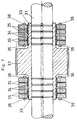
- an output sleeve is arranged on the shaft section 31, which consists of a toothed wheel 37 and sections 33 lying on both sides thereof.
- the shaft section 31 which consists of a toothed wheel 37 and sections 33 lying on both sides thereof.
- two inner double cone rings 34 are arranged with opposite conicity.
- the two partial rings of the outer double cone rings 35 which can be clamped against one another by means of clamping screws 36, sit on these. Grooves and a central bore are present as in the other exemplary embodiments.
Landscapes
- Engineering & Computer Science (AREA)
- General Engineering & Computer Science (AREA)
- Mechanical Engineering (AREA)
- Ocean & Marine Engineering (AREA)
- Clamps And Clips (AREA)
- Devices For Conveying Motion By Means Of Endless Flexible Members (AREA)
Applications Claiming Priority (2)
| Application Number | Priority Date | Filing Date | Title |
|---|---|---|---|
| DE4136216A DE4136216A1 (de) | 1991-11-02 | 1991-11-02 | Spannsatz |
| DE4136216 | 1991-11-02 |
Publications (1)
| Publication Number | Publication Date |
|---|---|
| EP0540911A1 true EP0540911A1 (fr) | 1993-05-12 |
Family
ID=6444015
Family Applications (1)
| Application Number | Title | Priority Date | Filing Date |
|---|---|---|---|
| EP92117514A Withdrawn EP0540911A1 (fr) | 1991-11-02 | 1992-10-14 | Dispositif de blocage |
Country Status (3)
| Country | Link |
|---|---|
| US (1) | US5496124A (fr) |
| EP (1) | EP0540911A1 (fr) |
| DE (1) | DE4136216A1 (fr) |
Cited By (2)
| Publication number | Priority date | Publication date | Assignee | Title |
|---|---|---|---|---|
| CN105065478A (zh) * | 2011-01-31 | 2015-11-18 | 西门子公司 | 用于将空心轴或毂固定在轴上的夹紧装置 |
| CN105240356A (zh) * | 2015-10-28 | 2016-01-13 | 湘潭电机股份有限公司 | 一种用于提供预应力的复合锥套装置 |
Families Citing this family (11)
| Publication number | Priority date | Publication date | Assignee | Title |
|---|---|---|---|---|
| DE9308717U1 (de) * | 1993-06-11 | 1994-10-20 | Müllenberg, Ralph, 41516 Grevenbroich | Konusspannanordnung |
| DE102011075583A1 (de) * | 2011-05-10 | 2012-11-15 | Siemens Aktiengesellschaft | Befestigung einer Axiallagerscheibe in einer magnetgelagerten Turbomaschine mittels einer Schrumpfscheibenverbindung |
| GB201117049D0 (en) * | 2011-10-04 | 2011-11-16 | Ecolok Ltd | Method and apparatus for gripping |
| CN102990019B (zh) * | 2012-11-29 | 2015-03-25 | 燕山大学 | 一种无径向间隙的结晶器振动偏心机构 |
| DE102013208568A1 (de) * | 2013-05-08 | 2014-11-13 | Lenze Drives Gmbh | Anordnung mit Hohlwelle, Antriebswelle und Spannvorrichtung |
| FI127781B (en) | 2015-01-21 | 2019-02-15 | Lappeenrannan Teknillinen Yliopisto | A rotor assembly for an axial magnetic bearing |
| CN105508447B (zh) * | 2016-01-19 | 2018-09-14 | 十堰风神汽车橡塑制品有限公司 | 一种新型组装式风扇联轴器 |
| CN106870548A (zh) * | 2017-03-27 | 2017-06-20 | 苏州标杆知识产权运营有限公司 | 一种机械压力机偏心轴 |
| US10473205B2 (en) * | 2017-07-21 | 2019-11-12 | Hewlett-Packard Development Company, L.P. | Metal compression rings |
| CZ310484B6 (cs) * | 2024-04-23 | 2025-07-30 | VÚTS, a.s. | Sestava hřídele a alespoň dvou akčních členů |
| DE102024124728A1 (de) * | 2024-08-29 | 2026-03-05 | Ringfeder Power Transmission Gmbh | Spannsatz |
Citations (14)
| Publication number | Priority date | Publication date | Assignee | Title |
|---|---|---|---|---|
| US1565264A (en) * | 1924-03-22 | 1925-12-15 | Dubi Boris | Adjustable eccentric |
| DE862847C (de) * | 1951-07-11 | 1953-01-12 | Ringfeder Gmbh | Spannringe |
| DE897773C (de) * | 1950-04-28 | 1953-11-23 | Ringfeder Gmbh | Einrichtung zur Befestigung eines Bolzens in einem Werkstueck |
| US2764437A (en) * | 1951-05-31 | 1956-09-25 | Skf Ind Inc | Press fitting joint and means for making and separating the same |
| US3375730A (en) * | 1965-10-18 | 1968-04-02 | Antonenko Fedor Arsentievich | Crank mechanism with adjustable eccentricity |
| DE1752371A1 (de) * | 1968-05-16 | 1971-06-03 | Heinrich Hermann | Walze mit aufgeschrumpften Ringen |
| CH541734A (de) * | 1971-08-04 | 1973-09-15 | Maschb Ing O Klammer | Einrichtung zur stufenlosen Verstellung des Hubes einer auf einer Exzenterwelle gelagerten Pleuelstange |
| FR2373357A1 (fr) * | 1976-12-10 | 1978-07-07 | Sulzer Ag | Procede et dispositif de fixation d'une came sur un arbre |
| DE2942531A1 (de) * | 1979-10-20 | 1981-04-30 | Werner 4100 Duisburg Winckelhaus | Vorrichtung zur befestigung eines nabenansatzes auf einer welle |
| DE3120224C1 (de) * | 1981-05-21 | 1982-12-09 | Ralph 4048 Grevenbroich Müllenberg | Konusspannanordnung |
| DE3338894A1 (de) * | 1983-10-27 | 1985-05-15 | Werner 4100 Duisburg Winckelhaus | Vorrichtung zur befestigung einer mit einem nabenansatz versehenen nabe auf einer welle |
| DE8514085U1 (de) * | 1985-05-10 | 1985-08-08 | Enderlein, Robby, 6368 Bad Vilbel | Spannvorrichtung für eine Wellen-Naben-Verbindung |
| DE3701876A1 (de) * | 1987-01-23 | 1988-08-18 | Ralph Muellenberg | Konusspannanordnung |
| DE3707716A1 (de) * | 1987-03-11 | 1988-09-29 | Hausmann Und Haensgen Fa | Spannsatz fuer naben-wellen-verbindungen |
Family Cites Families (5)
| Publication number | Priority date | Publication date | Assignee | Title |
|---|---|---|---|---|
| US2817142A (en) * | 1952-07-19 | 1957-12-24 | Timken Roller Bearing Co | Hydraulic assembly for removing interference-fitted rings |
| CH450829A (de) * | 1966-01-26 | 1968-04-30 | Metallschlauchfabrik Ag | Kupplungsanordnung für Wellen |
| US3782841A (en) * | 1972-02-18 | 1974-01-01 | W Winckelhaus | System for securing an annular member to a shaft for torque transmission therebetween |
| SE419574B (sv) * | 1980-09-19 | 1981-08-10 | Skf Nova Ab | Axelkoppling |
| US4906124A (en) * | 1988-02-22 | 1990-03-06 | Deere & Company | Multi-piece eccentric assembly |
-
1991
- 1991-11-02 DE DE4136216A patent/DE4136216A1/de not_active Ceased
-
1992
- 1992-10-14 EP EP92117514A patent/EP0540911A1/fr not_active Withdrawn
-
1994
- 1994-06-28 US US08/266,782 patent/US5496124A/en not_active Expired - Fee Related
Patent Citations (14)
| Publication number | Priority date | Publication date | Assignee | Title |
|---|---|---|---|---|
| US1565264A (en) * | 1924-03-22 | 1925-12-15 | Dubi Boris | Adjustable eccentric |
| DE897773C (de) * | 1950-04-28 | 1953-11-23 | Ringfeder Gmbh | Einrichtung zur Befestigung eines Bolzens in einem Werkstueck |
| US2764437A (en) * | 1951-05-31 | 1956-09-25 | Skf Ind Inc | Press fitting joint and means for making and separating the same |
| DE862847C (de) * | 1951-07-11 | 1953-01-12 | Ringfeder Gmbh | Spannringe |
| US3375730A (en) * | 1965-10-18 | 1968-04-02 | Antonenko Fedor Arsentievich | Crank mechanism with adjustable eccentricity |
| DE1752371A1 (de) * | 1968-05-16 | 1971-06-03 | Heinrich Hermann | Walze mit aufgeschrumpften Ringen |
| CH541734A (de) * | 1971-08-04 | 1973-09-15 | Maschb Ing O Klammer | Einrichtung zur stufenlosen Verstellung des Hubes einer auf einer Exzenterwelle gelagerten Pleuelstange |
| FR2373357A1 (fr) * | 1976-12-10 | 1978-07-07 | Sulzer Ag | Procede et dispositif de fixation d'une came sur un arbre |
| DE2942531A1 (de) * | 1979-10-20 | 1981-04-30 | Werner 4100 Duisburg Winckelhaus | Vorrichtung zur befestigung eines nabenansatzes auf einer welle |
| DE3120224C1 (de) * | 1981-05-21 | 1982-12-09 | Ralph 4048 Grevenbroich Müllenberg | Konusspannanordnung |
| DE3338894A1 (de) * | 1983-10-27 | 1985-05-15 | Werner 4100 Duisburg Winckelhaus | Vorrichtung zur befestigung einer mit einem nabenansatz versehenen nabe auf einer welle |
| DE8514085U1 (de) * | 1985-05-10 | 1985-08-08 | Enderlein, Robby, 6368 Bad Vilbel | Spannvorrichtung für eine Wellen-Naben-Verbindung |
| DE3701876A1 (de) * | 1987-01-23 | 1988-08-18 | Ralph Muellenberg | Konusspannanordnung |
| DE3707716A1 (de) * | 1987-03-11 | 1988-09-29 | Hausmann Und Haensgen Fa | Spannsatz fuer naben-wellen-verbindungen |
Cited By (3)
| Publication number | Priority date | Publication date | Assignee | Title |
|---|---|---|---|---|
| CN105065478A (zh) * | 2011-01-31 | 2015-11-18 | 西门子公司 | 用于将空心轴或毂固定在轴上的夹紧装置 |
| CN105065478B (zh) * | 2011-01-31 | 2018-11-20 | 西门子公司 | 用于将空心轴或毂固定在轴上的夹紧装置 |
| CN105240356A (zh) * | 2015-10-28 | 2016-01-13 | 湘潭电机股份有限公司 | 一种用于提供预应力的复合锥套装置 |
Also Published As
| Publication number | Publication date |
|---|---|
| DE4136216A1 (de) | 1993-05-06 |
| US5496124A (en) | 1996-03-05 |
Similar Documents
| Publication | Publication Date | Title |
|---|---|---|
| DE1801672C3 (de) | Spannfutter | |
| DE1625452C3 (de) | Vorrichtung zum loesbaren Verbinden zweier Verbindungskoerper,insbesondere einer Scheibe mit einer Welle | |
| CH659511A5 (de) | Kupplung zur reibschluessigen drehverbindung von maschinenteilen. | |
| EP0540911A1 (fr) | Dispositif de blocage | |
| DE4141818C2 (de) | Vorrichtungen zum Klemmen und Spannen | |
| DE2832917A1 (de) | Verbindungsanordnung | |
| WO1991007600A1 (fr) | Systeme de serrage conique | |
| DE2544498B2 (de) | Gewindering | |
| DE1099806B (de) | Spannsatz zwischen einem zylindrischen Bauteil und einem dazu konzentrisch angeordneten Koerper | |
| DE3000637A1 (de) | Loesbare kraftschluessige befestigung einer welle in einer nabe | |
| DE2422639C2 (de) | Elastische Kupplung | |
| DE1491029A1 (de) | Zahnaertzliches Handstueck | |
| DE3604454C1 (de) | Druckaufbaudorn zum druckdichten Befestigen eines Rohres in einer OEffnung eines Rohrbodens | |
| DE2318612B2 (de) | Elastische Wellenkupplung | |
| DE2317214C3 (de) | Elastische Wellenkupplung | |
| DE2659547A1 (de) | Vorrichtung zum verbinden von nabe und welle durch reibschluss | |
| DE2011012A1 (de) | Spannsatz zwischen einem zylindrischen Bauteil und einem dazu konzentrisch ange ordneten Korper | |
| DE3339186C1 (de) | Pneumatisch schaltbare Überlast-Klauenkupplung mit automatischer Entkupplung bei Drehmomentüberschreitung | |
| EP0574683B1 (fr) | Accouplement à friction d'un arbre avec un élément de machine | |
| DE19939729A1 (de) | Antriebsanordnung | |
| DE3626257C2 (fr) | ||
| DE8030671U1 (de) | Vorrichtung zur kraftschlüssigen Verbindung von Maschinenteilen o.dgl. | |
| AT288820B (de) | Reibwerkzeug | |
| AT226491B (de) | Mit Freilaufeinrichtung versehenes Getriebe zur Umwandlung der Drehbewegung eines Antriebsorganes in eine Axialverschiebung des angetriebenen Teiles | |
| DE2356604C3 (de) | Hydraulische Spannvorrichtung zum Befestigen eines Schraubbolzens mit einer Mutter unter Vorspannung |
Legal Events
| Date | Code | Title | Description |
|---|---|---|---|
| PUAI | Public reference made under article 153(3) epc to a published international application that has entered the european phase |
Free format text: ORIGINAL CODE: 0009012 |
|
| AK | Designated contracting states |
Kind code of ref document: A1 Designated state(s): DE ES FR GB IT |
|
| 17P | Request for examination filed |
Effective date: 19931104 |
|
| 17Q | First examination report despatched |
Effective date: 19931215 |
|
| RAP1 | Party data changed (applicant data changed or rights of an application transferred) |
Owner name: SCHULER PRESSEN GMBH & CO. |
|
| STAA | Information on the status of an ep patent application or granted ep patent |
Free format text: STATUS: THE APPLICATION IS DEEMED TO BE WITHDRAWN |
|
| 18D | Application deemed to be withdrawn |
Effective date: 19960208 |