EP0540955A1 - Vorrichtung zum Befestigen eines stabförmigen Dauermagneten - Google Patents
Vorrichtung zum Befestigen eines stabförmigen Dauermagneten Download PDFInfo
- Publication number
- EP0540955A1 EP0540955A1 EP92118146A EP92118146A EP0540955A1 EP 0540955 A1 EP0540955 A1 EP 0540955A1 EP 92118146 A EP92118146 A EP 92118146A EP 92118146 A EP92118146 A EP 92118146A EP 0540955 A1 EP0540955 A1 EP 0540955A1
- Authority
- EP
- European Patent Office
- Prior art keywords
- holder
- permanent magnet
- circuit board
- fastening
- shaped
- Prior art date
- Legal status (The legal status is an assumption and is not a legal conclusion. Google has not performed a legal analysis and makes no representation as to the accuracy of the status listed.)
- Granted
Links
Images


Classifications
-
- H—ELECTRICITY
- H01—ELECTRIC ELEMENTS
- H01F—MAGNETS; INDUCTANCES; TRANSFORMERS; SELECTION OF MATERIALS FOR THEIR MAGNETIC PROPERTIES
- H01F7/00—Magnets
- H01F7/02—Permanent magnets [PM]
- H01F7/0205—Magnetic circuits with PM in general
- H01F7/0221—Mounting means for PM, supporting, coating, encapsulating PM
-
- H—ELECTRICITY
- H05—ELECTRIC TECHNIQUES NOT OTHERWISE PROVIDED FOR
- H05K—PRINTED CIRCUITS; CASINGS OR CONSTRUCTIONAL DETAILS OF ELECTRIC APPARATUS; MANUFACTURE OF ASSEMBLAGES OF ELECTRICAL COMPONENTS
- H05K3/00—Apparatus or processes for manufacturing printed circuits
- H05K3/30—Assembling printed circuits with electric components, e.g. with resistors
- H05K3/301—Assembling printed circuits with electric components, e.g. with resistors by means of a mounting structure
-
- H—ELECTRICITY
- H05—ELECTRIC TECHNIQUES NOT OTHERWISE PROVIDED FOR
- H05K—PRINTED CIRCUITS; CASINGS OR CONSTRUCTIONAL DETAILS OF ELECTRIC APPARATUS; MANUFACTURE OF ASSEMBLAGES OF ELECTRICAL COMPONENTS
- H05K7/00—Constructional details common to different types of electric apparatus
- H05K7/02—Arrangements of circuit components or wiring on supporting structure
- H05K7/12—Resilient or clamping means for holding component to structure
Definitions
- the invention relates to an arrangement for fastening a rod-shaped permanent magnet on a circuit board, in particular on a printed circuit board.
- Such an arrangement is an atypical measure, since a permanent magnet is a non-electrical component, which is therefore not provided with contact pins, which, as a rule in electrical components, not only make contact with the conductor tracks provided on the printed circuit board, but also serve the mechanical fastening of the component in question.
- the resonant circuit coil of which is a magnetic sensor
- the measured value is formed by changing the magnetic properties of the resonant circuit coil or its coil core and the permanent magnet is used for biasing, in other words the operating point setting of the magnetic sensor, a suitable spatial assignment of the resonant circuit coil and permanent magnet is required.
- the resonant circuit coil is expediently arranged directly and thus line-free on a central circuit board of a measuring, control or data acquisition device carrying the means for processing and processing measured values and further electronic functional groups, this has the consequence that the permanent magnet is also on this PCB is to be attached.
- the usual fastening methods are not applicable. Tightening, for example by means of a clamp or retaining bridge screwed to the relevant printed circuit board, requires a considerable area of the printed circuit board which cannot be covered with conductor tracks. In addition, such an attachment is unsuitable because it does not interfere with the assembly flow PCB fits. Fastening the permanent magnet by direct gluing to the circuit board, apart from the need for a relatively exact positioning of the permanent magnet, does not permit readjustment and causes production delays due to the reaction times of the glue.
- the object of the present invention is therefore to provide an arrangement which allows a permanent magnet to be fastened to a printed circuit board under high-volume conditions.
- the solution to this problem provides that a holder receiving the permanent magnet is provided and that the holder can be connected to the circuit board in a latching manner.
- a preferred embodiment is characterized in that the holder is essentially U-shaped and two fixing pins and at least one locking pawl are formed on the side of the holder opposite the legs of the U-profile.
- the advantage that the invention offers is that a rod-shaped permanent magnet can be mounted, so to speak, by means of the holder according to the solution in the course of the assembly of a printed circuit board and, due to the latching connection provided, can ultimately be mechanically assembled.
- the greatest possible mutual spacing of the fixing pins allows the relatively coarse tolerances customary in printed circuit board bores, but also necessary for assembly, while in particular the U-shaped design means both replacement or subsequent insertion and easy adjustment and fastening of the permanent magnet Gluing allowed.
- the design of the holder causes a vibration-proof seat of the permanent magnet and thus suitability for use in the motor vehicle.
- a permanent magnet 1 is fastened in a U-shaped holder 2, the latter being arranged on a printed circuit board 3.
- ribs 6 and 7 pointing inwards are formed on the legs 4 and 5 of the U-shaped holder 2, which together with a certain resilience of the legs 4 and 5 are a holder of an inserted permanent magnet 1 and thus also allow mechanical handling of an assembly pre-assembled from the permanent magnet 1 and the holder 2.
- the holder 2 is provided with latches 8 and 9 and with fixing pins 10 and 11. This configuration requires suitable bores for the fixing pins 10 and 11 and the slots 8 and 9 assigned to the latches in the printed circuit board 3, on which the holder 2 is seated directly.
- the height of the permanent magnet 1 above the printed circuit board 3 is determined by the thickness of the web of the holder 2, which connects the legs 4 and 5 and is not specified.
- FIGS. 4 and 5 show a holder 12 on which, instead of the U-shaped profile for receiving a permanent magnet 1 with a rectangular cross-section, a cup-shaped holder, which is particularly suitable for holding a cylindrical permanent magnet, is formed.
- the cylindrical permanent magnet is largely encapsulated by the holder 12 and protected from mechanical damage.
- the permanent magnet can be attached directly to the circuit board.
- a window 14 mounted in the shell wall 13 is used to move an inserted permanent magnet, the length of which, in order to be able to move, must be a certain amount smaller than the distance between the end walls 15 and 16 of the holder 12.
- the window 14 is used for specifying an adhesive drop for attaching the permanent magnet in the holder 12.
- the latches designated 17 and 18 act in the same way as the latches 8 and 9 formed on the holder 2.
- the fixing pins 19 and 20 are in the embodiment according to FIGS. 4 and 5 on the End walls 15 and 16 formed.
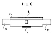
- FIG. 6 shows an embodiment variant in which two permanent magnets 21 and 22 are fastened in the holder 2.
- the additional, mutual displacement of the permanent magnets 21 and 22 provides a more flexible adjustment of the magnetic circuit in question.
Landscapes
- Engineering & Computer Science (AREA)
- Microelectronics & Electronic Packaging (AREA)
- Physics & Mathematics (AREA)
- Electromagnetism (AREA)
- Power Engineering (AREA)
- Manufacturing & Machinery (AREA)
- Magnetic Resonance Imaging Apparatus (AREA)
- Details Of Connecting Devices For Male And Female Coupling (AREA)
- Mounting Components In General For Electric Apparatus (AREA)
- Particle Accelerators (AREA)
- Permanent Field Magnets Of Synchronous Machinery (AREA)
- Mounting Of Printed Circuit Boards And The Like (AREA)
Abstract
Description
- Die Erfindung betrifft eine Anordnung zum Befestigen eines stabförmigen Dauermagneten auf einer Platine, insbesondere auf einer Leiterplatte. Eine solche Anordnung ist eine an sich untypische Maßnahme, da es sich bei einem Dauermagneten um ein nichtelektrisches Bauelement handelt, das demnach nicht mit Kontaktstiften versehen ist, die in der Regel bei elektrischen Bauteilen nicht allein der Kontaktierung mit den auf der Leiterplatte vorgesehenen Leiterbahnen sondern auch der mechanischen Befestigung des betreffenden Bauteils dienen.
- Ist ein derartiger Dauermagnet Teil eines magnetfeldgesteuerten Oszillators, dessen Schwingkreisspule einen magnetischen Sensor darstellt, d. h. die Meßwertbildung durch Änderung der magnetischen Eigenschaften der Schwingkreisspule bzw. deren Spulenkerns erfolgt und der Dauermagnet der Vormagnetisierung, mit anderen Worten der Arbeitspunkteinstellung des magnetischen Sensors dient, ist eine geeignete räumliche Zuordnung von Schwingkreisspule und Dauermagnet erforderlich.
- Wird in einem solchen Falle zweckmäßigerweise die Schwingkreisspule unmittelbar und somit leitungsfrei auf einer zentralen, die Mittel zur Meßwertaufbereitung und -verarbeitung sowie weitere elektronische Funktionsgruppen tragenden Leiterplatte eines Meß-, Steuer- oder Datenerfassungsgerätes angeordnet, hat dies zur Folge, daß der Dauermagnet ebenfalls auf dieser Leiterplatte zu befestigen ist. Dabei sind die üblichen Befestigungsmethoden nicht anwendbar. Ein Festschrauben beispielsweise mittels einer mit der betreffenden Leiterplatte verschraubten Schelle oder Haltebrücke beansprucht ein erhebliches Leiterplattenareal, das nicht mit Leiterbahnen belegt werden kann. Außerdem ist eine derartige Befestigung insofern ungeeignet, weil sie nicht in den Bestückungsfluß einer Leiterplatte paßt. Ein Befestigen des Dauermagneten durch unmittelbares Kleben auf die Leiterplatte läßt, vom Erfordernis einer relativ exakten Positionierung des Dauermagneten abgesehen, kein Nachjustieren zu und bedingt Fertigungsverzögerungen durch Einhalten von Reaktionszeiten des Klebers.
- Die Aufgabe der vorliegenden Erfindung besteht somit darin, eine Anordnung zu schaffen, die eine Befestigung eines Dauermagneten auf einer Leiterplatte unter Großserienbedingungen gestattet.
- Die Lösung dieser Aufgabe sieht vor, daß ein den Dauermagneten aufnehmender Halter vorgesehen ist und daß der Halter mit der Leiterplatte rastend verbindbar ist.
- Ein bevorzugtes Ausführungsbeispiel ist dadurch gekennzeichnet, daß der Halter im wesentlichen U-förmig profiliert ist und zwei Fixierzapfen und wenigstens eine Rastklinke an der den Schenkeln des U-Profils entgegengesetzten Seite des Halters ausgebildet sind.
- Der Vorteil, den die Erfindung bietet, ist darin zu sehen, daß ein stabförmiger Dauermagnet mittels des lösungsgemäßen Halters sozusagen im Zuge der Bestückung einer Leiterplatte montiert werden kann und aufgrund der vorgesehenen Rastverbindung letzten Endes maschinell montierbar ist. Dabei läßt der möglichst große, gegenseitige Abstand der Fixierzapfen die bei Leiterplattenbohrungen üblichen, für die Bestückung aber auch notwendigen, relativ groben Toleranzen zu, während insbesondere die U-förmige Ausbildung sowohl ein Austauschen oder nachträgliches Einsetzen als auch ein leichtes Justieren und Befestigen des Dauermagneten durch Kleben gestattet. Ferner bewirkt die Bauform des Halters einen rüttelsicheren Sitz des Dauermagneten und somit eine Eignung für die Verwendung im Kraftfahrzeug.
- Im folgenden sei die Erfindung anhand der Zeichnungen näher erläutert. Es zeigen
- Fig. 1 eine perspektivische Übersichtsdarstellung der erfindungsgemäßen Anordnung,
- Fig. 2 eine perspektivische Darstellung eines bevorzugten Ausführungsbeispiels des Halters,
- Fig. 3 einen Schnitt des Halters gemäß dem mit der Fig. 2 dargestellten Ausführungsbeispiel,
- Fig. 4 einen Längsschnitt eines weiteren Ausführungsbeispiels des Halters,
- Fig. 5 einen Querschnitt des Halters gemäß Fig. 4,
- Fig. 6 eine Draufsicht auf den Halter gemäß Fig. 2, wobei im Halter zwei Dauermagnete aufgenommen sind.
- Gemäß Fig. 1 ist ein Dauermagnet 1 in einem U-förmigen Halter 2 befestigt, wobei letzterer auf einer Leiterplatte 3 angeordnet ist.
- Wie aus der Fig. 2 und der Schnittdarstellung Fig. 3 ersichtlich ist, sind an den Schenkeln 4 und 5 des U-förmigen Halters 2 nach innen weisende Rippen 6 und 7 angeformt, die zusammen mit einer gewissen Federungsfähigkeit der Schenkel 4 und 5 eine Halterung eines eingesetzten Dauermagneten 1 und somit auch eine maschinelle Handhabung einer aus dem Dauermagneten 1 und dem Halter 2 vormontierten Baugruppe gestatten. Außerdem ist der Halter 2 mit Rastklinken 8 und 9 sowie mit Fixierzapfen 10 und 11 versehen. Diese Ausbildung bedingt geeignete Bohrungen für die Fixierzapfen 10 und 11 sowie den Rastklinken 8 und 9 zugeordnete Schlitze in der Leiterplatte 3, auf welcher der Halter 2 unmittelbar aufsitzt. Die Höhe des Dauermagneten 1 über der Leiterplatte 3 wird dabei durch die Stärke des die Schenkel 4 und 5 verbindenden, nicht näher bezeichneten Steges des Halters 2 bestimmt.
- Denkbar ist in diesem Zusammenhang auch die Anordnung auf einer Platine oder Leiterplatte, auf der im wesentlichen nur die Bauelemente des betreffenden Sensors angeordnet sind und die mittels einer geeigneten, mechanisch zweckdienlichen Steckverbindung mit der Leiterplatte 3 verbunden ist oder an einer anderen Stelle des betreffenden Gerätes befestigt und mit der Leiterplatte 3 in geeigneter Weise verdrahtet ist.
- Die Fig. 4 und 5 zeigen einen Halter 12, an welchem anstatt des U-Profils zur Aufnahme vorzugsweise eines Dauermagneten 1 mit rechteckförmigem Querschnitt eine insbesondere für die Halterung eines zylindrischen Dauermagneten geeignete, schalenförmige Fassung ausgebildet ist. Bei dieser Lösung ist der zylindrische Dauermagnet durch den Halter 12 weitgehend gekapselt und vor mechanischen Beschädigungen geschützt. Außerdem kann der Dauermagnet unmittelbar auf der Leiterplatte befestigt werden. Ein in der Schalenwand 13 angebrachtes Fenster 14 dient dem Verschieben eines eingelegten Dauermagneten, dessen Länge, um ein Verschieben zu ermöglichen, um ein gewisses Maß kleiner sein muß als der Abstand der Stirnwände 15 und 16 des Halters 12. Außerdem dient das Fenster 14 dem Angeben eines Klebstofftropfens zum Befestigen des Dauermagneten im Halter 12. Die mit 17 und 18 bezeichneten Rastklinken wirken in gleicher Weise wie die am Halter 2 ausgebildeten Rastklinken 8 und 9. Die Fixierzapfen 19 und 20 sind bei dem Ausführungsbeispiel gemäß den Fig. 4 und 5 an den Stirnwänden 15 und 16 angeformt.
- Die Fig. 6 zeigt eine Ausführungsvariante, bei der in dem Halter 2 zwei Dauermagnete 21 und 22 befestigt sind. In diesem Falle ist durch die zusätzliche, gegenseitige Verschiebbarkeit der Dauermagnete 21 und 22 eine flexiblere Justierung des betreffenden Magnetkreises gegeben.
Claims (5)
- Anordnung zum Befestigen eines stabförmigen Dauermagneten auf eine Platine, insbesondere auf einer Leiterplatte,
dadurch gekennzeichnet,
daß ein den Dauermagneten (1) aufnehmender Halter (2) vorgesehen ist und
daß der Halter (2) mit der Leiterplatte (3) rastend verbindbar ist. - Anordnung nach Anspruch 1,
dadurch gekennzeichnet,
daß der Dauermagnet (1) in dem Halter (2) in axialer Richtung verschiebbar ist und der Halter (2) an seiner der Leiterplatte (3) abgewandten Seite eine Öffnung aufweist. - Anordnung nach Anspruch 1,
dadurch gekennzeichnet,
daß an dem Halter (2) zwei Fixierzapfen (10, 11) und wenigstens eine Rastklinke (8 bzw. 9) ausgebildet sind. - Anordnung nach Anspruch 1,
dadurch gekennzeichnet,
daß der Halter (2) im wesentlichen U-förmig profiliert ist und die Fixierzapfen (10, 11) und wenigstens eine Rastklinke (8 bzw. 9) an der den Schenkeln (4, 5) des U-Profils entgegengesetzten Seite des Halters (2) ausgebildet sind. - Anordnung nach Anspruch 1,
dadurch gekennzeichnet,
daß der Halter (12) schalen- oder schellenförmig ausgebildet ist und
daß die Fixierzapfen (19, 20) und wenigstens eine Rastklinke (17 bzw. 18) an der Seite des Halters (12) ausgebildet sind, an welcher die den Dauermagneten aufnehmende Öffnung vorgesehen ist.
Applications Claiming Priority (2)
| Application Number | Priority Date | Filing Date | Title |
|---|---|---|---|
| DE9113780U | 1991-11-06 | ||
| DE9113780U DE9113780U1 (de) | 1991-11-06 | 1991-11-06 | Anordnung zum Befestigen eines stabförmigen Dauermagneten |
Publications (2)
| Publication Number | Publication Date |
|---|---|
| EP0540955A1 true EP0540955A1 (de) | 1993-05-12 |
| EP0540955B1 EP0540955B1 (de) | 1996-03-27 |
Family
ID=6872968
Family Applications (1)
| Application Number | Title | Priority Date | Filing Date |
|---|---|---|---|
| EP92118146A Expired - Lifetime EP0540955B1 (de) | 1991-11-06 | 1992-10-23 | Vorrichtung zum Befestigen eines stabförmigen Dauermagneten |
Country Status (4)
| Country | Link |
|---|---|
| EP (1) | EP0540955B1 (de) |
| JP (1) | JPH0559807U (de) |
| AT (1) | ATE136193T1 (de) |
| DE (2) | DE9113780U1 (de) |
Cited By (3)
| Publication number | Priority date | Publication date | Assignee | Title |
|---|---|---|---|---|
| US5673757A (en) * | 1992-12-23 | 1997-10-07 | Vibra Blade New Zealand Limited | Ground opening device |
| WO2002085084A1 (de) * | 2001-04-12 | 2002-10-24 | Siemens Ag Österreich | Halteelement für elektrische bauteile zur montage auf schaltungsträgern |
| WO2003054959A3 (de) * | 2001-12-20 | 2004-04-29 | Eupec Gmbh & Co Kg | Schaltungsanordnung mit elektronischen bauelementen auf einem isolierenden trägersubstrat |
Families Citing this family (1)
| Publication number | Priority date | Publication date | Assignee | Title |
|---|---|---|---|---|
| JPH081850B2 (ja) * | 1992-09-19 | 1996-01-10 | 株式会社吉川国工業所 | 磁石の取付構造 |
Citations (2)
| Publication number | Priority date | Publication date | Assignee | Title |
|---|---|---|---|---|
| EP0177798A1 (de) * | 1984-10-09 | 1986-04-16 | Mannesmann Kienzle GmbH | An einer Platine lösbar befestigbarer Elektromagnet |
| DE3844310A1 (de) * | 1988-06-06 | 1989-12-07 | Bosch Gmbh Robert | Halterung fuer freistehende elektronische bauteile |
Family Cites Families (1)
| Publication number | Priority date | Publication date | Assignee | Title |
|---|---|---|---|---|
| JPS61234013A (ja) * | 1986-04-17 | 1986-10-18 | Taamo:Kk | 係合具 |
-
1991
- 1991-11-06 DE DE9113780U patent/DE9113780U1/de not_active Expired - Lifetime
-
1992
- 1992-10-23 DE DE59205837T patent/DE59205837D1/de not_active Expired - Fee Related
- 1992-10-23 AT AT92118146T patent/ATE136193T1/de active
- 1992-10-23 EP EP92118146A patent/EP0540955B1/de not_active Expired - Lifetime
- 1992-11-05 JP JP076229U patent/JPH0559807U/ja active Pending
Patent Citations (2)
| Publication number | Priority date | Publication date | Assignee | Title |
|---|---|---|---|---|
| EP0177798A1 (de) * | 1984-10-09 | 1986-04-16 | Mannesmann Kienzle GmbH | An einer Platine lösbar befestigbarer Elektromagnet |
| DE3844310A1 (de) * | 1988-06-06 | 1989-12-07 | Bosch Gmbh Robert | Halterung fuer freistehende elektronische bauteile |
Cited By (4)
| Publication number | Priority date | Publication date | Assignee | Title |
|---|---|---|---|---|
| US5673757A (en) * | 1992-12-23 | 1997-10-07 | Vibra Blade New Zealand Limited | Ground opening device |
| WO2002085084A1 (de) * | 2001-04-12 | 2002-10-24 | Siemens Ag Österreich | Halteelement für elektrische bauteile zur montage auf schaltungsträgern |
| US6801432B2 (en) | 2001-04-12 | 2004-10-05 | Siemens Ag Osterreich | Retainer element for electrical components for assembly on circuit supports |
| WO2003054959A3 (de) * | 2001-12-20 | 2004-04-29 | Eupec Gmbh & Co Kg | Schaltungsanordnung mit elektronischen bauelementen auf einem isolierenden trägersubstrat |
Also Published As
| Publication number | Publication date |
|---|---|
| EP0540955B1 (de) | 1996-03-27 |
| ATE136193T1 (de) | 1996-04-15 |
| DE59205837D1 (de) | 1996-05-02 |
| JPH0559807U (ja) | 1993-08-06 |
| DE9113780U1 (de) | 1991-12-19 |
Similar Documents
| Publication | Publication Date | Title |
|---|---|---|
| DE19739298C1 (de) | Vorrichtung zur Befestigung eines Entfernungssensors an einem Kraftfahrzeug | |
| DE4129961C2 (de) | Videoendoskop mit Festkörperbildaufnahmevorrichtung | |
| EP1130368B1 (de) | Messgerät mit Seilsonde und Verfahren zum Kürzen der Seilsonde | |
| DE10038001B4 (de) | Sensoranordnung | |
| EP3685476B1 (de) | Modularer anschlussblock | |
| DE4416667B4 (de) | Festkörperelektrolytkondensator | |
| EP0540955B1 (de) | Vorrichtung zum Befestigen eines stabförmigen Dauermagneten | |
| DE10201880B4 (de) | Magnetostriktives Sensor-Element | |
| DE102011082755A1 (de) | Montagevorrichtung eines Längenmesssystems | |
| DE19839118C2 (de) | Konstruktionsanordnung für die Befestigung eines Bauelements auf einer gedruckten Leiterplatte und elektronische Geräte mit dieser Konstruktion | |
| DE29504286U1 (de) | Eckenprofil | |
| DE10106478B4 (de) | Magnetische Längenmessvorrichtung | |
| DE9102779U1 (de) | Schwingkreisspule für einen magnetfeldgesteuerten Oszillator | |
| DE3610613A1 (de) | Messinstrumenten-gehaeuse | |
| DE2652672A1 (de) | Gehaeuse fuer geraete der elektrischen nachrichten- und messtechnik | |
| DE102007038847A1 (de) | Stator für einen Linearmotor | |
| EP0972954A2 (de) | Befestigungssystem | |
| DE102006036746A1 (de) | Positionsmesseinrichtung und Verfahren zur Montage einer Positionsmesseinrichtung | |
| DE9218701U1 (de) | Schrittmotor | |
| DE3922237C2 (de) | ||
| EP3853621B1 (de) | Formteil zur aufnahme eines c-förmigen magnetfeldkonzentrationselements, magnetfeldkonzentrationsvorrichtung und stromrichter | |
| DE102018215496A1 (de) | Sensorvorrichtung aufweisend ein Gehäuse und einen wenigstens einachsigen Vibrationssensor | |
| DE29718791U1 (de) | Drehwertgeber | |
| DE2817469C2 (de) | Montageelement für die Befestigung von Drucktastern, Leuchtmeldern o.dgl. an einer Befestigungsplatte | |
| DE102024134943A1 (de) | Befestigungsvorrichtung und damit gebildete Einrichtung |
Legal Events
| Date | Code | Title | Description |
|---|---|---|---|
| PUAI | Public reference made under article 153(3) epc to a published international application that has entered the european phase |
Free format text: ORIGINAL CODE: 0009012 |
|
| AK | Designated contracting states |
Kind code of ref document: A1 Designated state(s): AT CH DE ES FR GB IT LI |
|
| 17P | Request for examination filed |
Effective date: 19931022 |
|
| 17Q | First examination report despatched |
Effective date: 19940603 |
|
| GRAA | (expected) grant |
Free format text: ORIGINAL CODE: 0009210 |
|
| RAP1 | Party data changed (applicant data changed or rights of an application transferred) |
Owner name: VDO ADOLF SCHINDLING AG |
|
| AK | Designated contracting states |
Kind code of ref document: B1 Designated state(s): AT CH DE ES FR GB IT LI |
|
| PG25 | Lapsed in a contracting state [announced via postgrant information from national office to epo] |
Ref country code: IT Free format text: LAPSE BECAUSE OF FAILURE TO SUBMIT A TRANSLATION OF THE DESCRIPTION OR TO PAY THE FEE WITHIN THE PRESCRIBED TIME-LIMIT;WARNING: LAPSES OF ITALIAN PATENTS WITH EFFECTIVE DATE BEFORE 2007 MAY HAVE OCCURRED AT ANY TIME BEFORE 2007. THE CORRECT EFFECTIVE DATE MAY BE DIFFERENT FROM THE ONE RECORDED. Effective date: 19960327 Ref country code: ES Free format text: THE PATENT HAS BEEN ANNULLED BY A DECISION OF A NATIONAL AUTHORITY Effective date: 19960327 |
|
| REF | Corresponds to: |
Ref document number: 136193 Country of ref document: AT Date of ref document: 19960415 Kind code of ref document: T |
|
| REF | Corresponds to: |
Ref document number: 59205837 Country of ref document: DE Date of ref document: 19960502 |
|
| GBT | Gb: translation of ep patent filed (gb section 77(6)(a)/1977) |
Effective date: 19960524 |
|
| ET | Fr: translation filed | ||
| PG25 | Lapsed in a contracting state [announced via postgrant information from national office to epo] |
Ref country code: AT Effective date: 19961023 |
|
| PG25 | Lapsed in a contracting state [announced via postgrant information from national office to epo] |
Ref country code: CH Effective date: 19961031 Ref country code: LI Effective date: 19961031 |
|
| PLBE | No opposition filed within time limit |
Free format text: ORIGINAL CODE: 0009261 |
|
| STAA | Information on the status of an ep patent application or granted ep patent |
Free format text: STATUS: NO OPPOSITION FILED WITHIN TIME LIMIT |
|
| 26N | No opposition filed | ||
| REG | Reference to a national code |
Ref country code: CH Ref legal event code: PL |
|
| PGFP | Annual fee paid to national office [announced via postgrant information from national office to epo] |
Ref country code: FR Payment date: 20001012 Year of fee payment: 9 |
|
| PGFP | Annual fee paid to national office [announced via postgrant information from national office to epo] |
Ref country code: DE Payment date: 20011217 Year of fee payment: 10 |
|
| REG | Reference to a national code |
Ref country code: GB Ref legal event code: IF02 |
|
| PG25 | Lapsed in a contracting state [announced via postgrant information from national office to epo] |
Ref country code: FR Free format text: LAPSE BECAUSE OF NON-PAYMENT OF DUE FEES Effective date: 20020628 |
|
| REG | Reference to a national code |
Ref country code: FR Ref legal event code: ST |
|
| PGFP | Annual fee paid to national office [announced via postgrant information from national office to epo] |
Ref country code: GB Payment date: 20021010 Year of fee payment: 11 |
|
| PG25 | Lapsed in a contracting state [announced via postgrant information from national office to epo] |
Ref country code: DE Free format text: LAPSE BECAUSE OF NON-PAYMENT OF DUE FEES Effective date: 20030501 |
|
| PG25 | Lapsed in a contracting state [announced via postgrant information from national office to epo] |
Ref country code: GB Free format text: LAPSE BECAUSE OF NON-PAYMENT OF DUE FEES Effective date: 20031023 |
|
| GBPC | Gb: european patent ceased through non-payment of renewal fee |
Effective date: 20031023 |