EP0540958B1 - Inductance toroidale - Google Patents
Inductance toroidale Download PDFInfo
- Publication number
- EP0540958B1 EP0540958B1 EP92118169A EP92118169A EP0540958B1 EP 0540958 B1 EP0540958 B1 EP 0540958B1 EP 92118169 A EP92118169 A EP 92118169A EP 92118169 A EP92118169 A EP 92118169A EP 0540958 B1 EP0540958 B1 EP 0540958B1
- Authority
- EP
- European Patent Office
- Prior art keywords
- partial windings
- partial
- toroidal inductor
- winding
- inductor according
- Prior art date
- Legal status (The legal status is an assumption and is not a legal conclusion. Google has not performed a legal analysis and makes no representation as to the accuracy of the status listed.)
- Expired - Lifetime
Links
- 238000004804 winding Methods 0.000 claims description 82
- 239000004020 conductor Substances 0.000 claims description 12
- 239000002826 coolant Substances 0.000 claims description 10
- 238000001816 cooling Methods 0.000 claims description 6
- 230000002093 peripheral effect Effects 0.000 claims description 6
- 230000000295 complement effect Effects 0.000 claims description 2
- 230000013011 mating Effects 0.000 claims 2
- 229910052751 metal Inorganic materials 0.000 description 7
- 239000002184 metal Substances 0.000 description 7
- RYGMFSIKBFXOCR-UHFFFAOYSA-N Copper Chemical compound [Cu] RYGMFSIKBFXOCR-UHFFFAOYSA-N 0.000 description 4
- 229910052802 copper Inorganic materials 0.000 description 4
- 239000010949 copper Substances 0.000 description 4
- 229910000831 Steel Inorganic materials 0.000 description 3
- 238000005520 cutting process Methods 0.000 description 3
- 239000010959 steel Substances 0.000 description 3
- XEEYBQQBJWHFJM-UHFFFAOYSA-N Iron Chemical group [Fe] XEEYBQQBJWHFJM-UHFFFAOYSA-N 0.000 description 2
- 238000005452 bending Methods 0.000 description 2
- 239000007788 liquid Substances 0.000 description 2
- 239000007787 solid Substances 0.000 description 2
- 238000003466 welding Methods 0.000 description 2
- 238000004026 adhesive bonding Methods 0.000 description 1
- WYTGDNHDOZPMIW-RCBQFDQVSA-N alstonine Natural products C1=CC2=C3C=CC=CC3=NC2=C2N1C[C@H]1[C@H](C)OC=C(C(=O)OC)[C@H]1C2 WYTGDNHDOZPMIW-RCBQFDQVSA-N 0.000 description 1
- 229910052782 aluminium Inorganic materials 0.000 description 1
- XAGFODPZIPBFFR-UHFFFAOYSA-N aluminium Chemical compound [Al] XAGFODPZIPBFFR-UHFFFAOYSA-N 0.000 description 1
- 239000011324 bead Substances 0.000 description 1
- 238000005219 brazing Methods 0.000 description 1
- 239000003990 capacitor Substances 0.000 description 1
- 238000005266 casting Methods 0.000 description 1
- 239000000919 ceramic Substances 0.000 description 1
- 238000006073 displacement reaction Methods 0.000 description 1
- 238000010292 electrical insulation Methods 0.000 description 1
- 230000004907 flux Effects 0.000 description 1
- 239000011888 foil Substances 0.000 description 1
- 239000003365 glass fiber Substances 0.000 description 1
- 238000009434 installation Methods 0.000 description 1
- 239000012212 insulator Substances 0.000 description 1
- 239000000463 material Substances 0.000 description 1
- 238000010791 quenching Methods 0.000 description 1
- 230000000171 quenching effect Effects 0.000 description 1
- 239000011347 resin Substances 0.000 description 1
- 229920005989 resin Polymers 0.000 description 1
- 238000005476 soldering Methods 0.000 description 1
- 239000011343 solid material Substances 0.000 description 1
- 125000006850 spacer group Chemical group 0.000 description 1
- 238000003892 spreading Methods 0.000 description 1
- 230000007704 transition Effects 0.000 description 1
Images
Classifications
-
- H—ELECTRICITY
- H01—ELECTRIC ELEMENTS
- H01F—MAGNETS; INDUCTANCES; TRANSFORMERS; SELECTION OF MATERIALS FOR THEIR MAGNETIC PROPERTIES
- H01F27/00—Details of transformers or inductances, in general
- H01F27/28—Coils; Windings; Conductive connections
- H01F27/2895—Windings disposed upon ring cores
-
- H—ELECTRICITY
- H01—ELECTRIC ELEMENTS
- H01F—MAGNETS; INDUCTANCES; TRANSFORMERS; SELECTION OF MATERIALS FOR THEIR MAGNETIC PROPERTIES
- H01F37/00—Fixed inductances not covered by group H01F17/00
- H01F37/005—Fixed inductances not covered by group H01F17/00 without magnetic core
Definitions
- the invention is based on a toroidal throttle according to the preamble of patent claim 1.
- the invention relates to a prior art, as is known from DE-AS 1 115 829.
- the high-voltage choke coil specified there with a solid material winding consisting of 2 parallel partial conductors with 8 turns around a ring-shaped iron core the partial conductors have slots lying one above the other perpendicular to the surface of the iron core and not made to the edge of the partial conductor, in order to reduce eddy current losses.
- These partial conductors do not have any notable area-like support and there is no peripheral clamping.
- a ring transformer is known in which the winding conductors of the primary windings and the secondary windings are designed in a sector-shaped cross-section and alternately windings of the primary and secondary windings lie side by side in the circumferential direction.
- the secondary windings are liquid cooled.
- Inner conductor sections of the primary and secondary winding have a greater radial height than the outer conductor sections.
- the one into a ring interconnected transformer coils are housed in a jacket.
- This throttle structure requires a relatively large volume. In the event of a short circuit, the stability and mutual support of the winding parts are unsatisfactory.
- a commutation choke for converter systems made of twisted stranded wires is known, in which the non-segmented turns of the coil consist of many conductor strands which are interwoven in a tubular manner.
- the cross section of the tubular conductor is compressed into the shape of a rectangle.
- Several tubular or rectangular conductors can be arranged concentrically to one another.
- a toroidal air choke coil which has a medium inductance and can be loaded with a current which is strongly affected by harmonics.
- Such chokes are used as swinging and quenching chokes in power converters of mass transit vehicles.
- Such a choke is not suitable for short-circuit currents of the order of 100 kA - 140 kA, as can occur in high-performance converters due to ignition.
- Such short-circuit currents can, for. B. occur when in a bridge circuit 2 belonging to the same phase unintentionally or incorrectly ignite simultaneously and thus short-circuit the intermediate circuit capacitor of a converter with a DC intermediate circuit.
- the invention solves the problem of further developing a toroidal choke of the type mentioned at the outset in such a way that it can be used for currents of 100 100 kA and has a minimal volume and small losses.
- An advantage of the invention is that the segment throttle can be connected in series or in parallel from a plurality of segments of a toroid or annular bead after the windings have been assembled. Relatively dimensionally stable segments with high current carrying capacity can be used, which do not have to be able to be wound. A high mechanical strength of the toroidal choke can thus be achieved.
- the toroidal choke is easy to assemble, while ensuring a high short-circuit strength.
- a given installation volume can be better used, whereby the geometry of the toroidal choke can be reproduced very precisely.
- the number of turns and thus the inductance of the toroidal choke can be easily changed or set.
- the copper used for the segments can be stressed up to several times its yield point.
- a high fill factor with a large passage area for the magnetic field can be achieved with minimal leakage flux.
- a modular choke structure is possible by choosing more or fewer turns or radially offset turns.
- the chokes can be rectangular on the outside. Natural or liquid cooling with forced circulation, e.g. Oil cooling are possible.
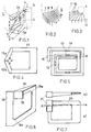
- (1) denotes a partial toroidal choke, which is constructed from a plurality of U-shaped winding elements or segmented partial windings (2).
- the partial windings (2) are arranged in a ring around a central, cylindrical recess (6) and each have a lower leg (2a) and an upper leg (2b).
- the partial windings (2) At the inner edge (4), the partial windings (2) have a width a that is smaller than a width b on their outer edge (5).
- the two legs (2a, 2b) have a height c near the inner edge (4) which is greater than their height d on the outer edge (5).
- the widths a and b are dimensioned so that the available volume for the toroidal choke (1) is used well.
- the associated heights c and d are dimensioned such that a current cross-sectional area through each partial winding (2) is the same.
- electrical connecting elements (3) connect the individual partial windings (2) to form a single toroidal turn or connect them in series.
- the toroidal choke (1) has 360 / ⁇ partial windings, where ⁇ denotes a segment pitch angle measured in degrees.
- FIG. 2 shows a section around a central recess (6) of a plurality of separate segmented partial windings arranged in a circle, the partial windings (7 - 9) adjacent to one another having a different length (1) in the radial direction.
- Such a staggering enables a high element density or number of turns of the toroidal choke (1) to be achieved. In this way, a high fill factor can be obtained with a large conductor cross section.
- Fig. 3 shows a detail of a toroidal choke (1) with a plurality of partial windings (10), which have different lengths in the radial direction and rectangular boundaries along the perpendicular surfaces (11, 12) on the outer edge.
- the toroidal throttle (1) can be adapted to a given volume.
- the external boundary also z. B. 5-sided, 6-sided, etc. could be selected.
- Fig. 4 shows a U-shaped partial winding (13) with 2 symmetrical, angled connecting elements (13a, 13b) which have an internal angle ( ⁇ ) in the range of 90 ° - 150 °, preferably in the range of 100 ° - 130 ° between them lock in.
- Such partial windings (13) can, for. B. made of aluminum or copper, made as flat sheet metal cuts and used in multiple layers if necessary.
- Fig. 5 shows a partial winding or a winding element (14) with several serpentine windings arranged one above the other, which are mutually insulated by means of electrically insulating spacers or insulators (15).
- the reference number (16) denotes one Connection area and the reference number (17) an externally folded and insulated connection end.
- Fig. 6 shows a partial winding (18) in an angular profile with chamfered inner corners (18a) and enlarged outer surfaces, which are obtained by bending from a sheet metal cut. (19) denotes connection areas for a screw connection, not shown. With similar geometry, massive partial windings (18) z. B. cast, pressed or deep drawn.
- Fig. 7a shows a partial winding (20) made of stranded wire, which is cast with a thermal resin to form a compact, dimensionally stable element.
- (21) a connection profile is designated.
- Fig. 7b shows a sectional view along a line A-A in Fig. 7a.
- a partial winding (20) can also be produced from individual sheet metal strips by gluing, the sheet metal strips crumpling, i. H. are twisted so that the outer sheet metal strips come cyclically inwards and the inner ones outwards. A small current displacement is thus achieved.
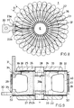
- FIG. 8 shows a toroidal choke (1) with a plurality of winding segments or partial windings (22), each separated by insulating foils or insulating layers (23), which are arranged in a circle around the central recess (6) and whose geometry can be better seen in FIG. 10 are.
- the segment pitch angle is again designated with ⁇ .
- 2 separately designed power connection elements (30) and (31) are attached, which can be seen better in FIG. 9.
- the insulating film (23) is slotted in the outer area as seen in the radial direction, so that there it has an upper and lower insulating film section (23a, 23b), which sections in FIG.
- the power connector (30) forms z. B. the beginning of the overall winding and the power connector (31), the z. B. could also be led out horizontally, the end.
- FIG. 9 shows the toroidal choke (1) according to FIG. 8 in a vertical cross section through its center and additionally a central clamping bolt (28) in the recess (6), upper and lower insulating plates (25), an upper disk-shaped clamping plate (26) , a lower disc-shaped clamping plate (27) and an electrically insulated pressure bandage (29) around the central part of the torus, d. H. around an outer edge (41) of the partial windings (22).
- the high-strength tensioning structure made of steel or a glass fiber material, is designed in such a way that it can absorb the majority of the expansion forces of the winding that occur during a surge current load. (In the case of partial windings from a simple sheet metal cut, the insulating plates (25) would be provided with radial grooves.)
- the central clamping bolt (28) is connected to steel disc-shaped clamping plates (26, 27) by thread.
- the clamping bolt (28) has a central cavity or coolant channel (28a) in its interior. It is electrically insulated from the partial windings (22) by insulating rings (24).
- a coolant inflow channel (34) and a coolant outflow channel (35) can be provided in a partial winding (2).
- the arrows show the direction of flow of the coolant.
- coolant can be drawn into the interior of the toroidal throttle (1) through slot-shaped openings or coolant inflow channels (32), and from there through coolant outflow channels (33) and the coolant channel (28a) inside the clamping bolt (28) get outside.
- the current heat to be dissipated can alternatively or additionally also be dissipated to the surroundings by means of cooling fins (not shown). Transition points to an adjacent, partial winding (22) lying behind are identified by (39).
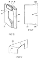
- FIG. 10 shows a segment or a partial winding (22) of the toroidal choke (1) according to FIG. 8 from a solid winding in a perspective view in detail.
- the partial winding (22) has a 1st or initial connection piece (36) and a 2nd or end connection piece (37) with a lateral, vertical pressure contact surface (37 ') and a horizontal contact surface (37'') through a recess (38) are spaced apart.
- the upper insulating film section (23a) is pushed into this recess (38) during assembly of the toroidal choke (1).
- the remaining part of the insulating film (23) serves for the electrical insulation of a partial winding (22) from the neighboring one, cf. 8 and 11.
- An electrical connection is guaranteed by the contact pressure.
- start and end connecting pieces (36, 37) fit to one another or are designed to be complementary to one another, so that area contact is ensured when adjacent partial windings (22) are applied.
- Relatively thick partial windings (22) can be produced in the desired, spread shape by casting.
- Flat partial windings (22) can be made from an annular disc by cutting along a cutting line leading from the inside outwards z. B. by means of a laser beam and subsequent bending or spreading.
- Adjacent partial windings (22) are then soldered or preferably welded along these cutting lines in order to obtain an overall winding.
- Fig. 12 shows a section of a partial winding (39) with a flat design and enlarged outer surfaces to reduce high-frequency losses.
- An arrow (B) points in the direction of the connection point, not shown.
- the connecting elements can be soft-soldered, hard-soldered or welded. Press and screw connections are suitable for solid partial windings.
- the partial windings (2) are inserted one after the other radially into a winding body, not shown, and the contact points z. B. fixed by screws.
Landscapes
- Engineering & Computer Science (AREA)
- Power Engineering (AREA)
- Coils Of Transformers For General Uses (AREA)
Claims (10)
- Inductance toroïdale (1)a) en plusieurs parties de bobinages respectivement en bobinages partiels (2, 7 - 10, 13, 18, 22, 39), disposés côte à côte en tore,b) dont chaque bobinage partiel présente au moins une spire etc) avec au moins un élément de liaison (3 ; 36 ; 37) pour le branchement en série et/ou en parallèle des bobinages partiels qui sont en liaison électrique,d) avec lequel la largeur (a) des membres (2a, 2b) des bobinages partiels (2) sont plus petit dans un périmètre central intérieur (4) du tore, que la largeur (b) au bord extérieur (5) de la périphérie
caractérisée en ce que,e) les bobinages partiels (2) présentent selon leur longueur une surface de coupe transversale au moins approximativement constante etf) sont entourés d'un bandage de contrainte périphérique (29). - Inductance toroïdale selon la revendication 1, caractérisée en ce que la hauteur (c) des membres (2a, 2b) dans le périmètre intérieur central (4) est supérieure à la hauteur (d) au bord périphérique extérieur (5) du tore.
- Inductance toroïdale selon l'une quelconque des revendications 1 ou 2, caractérisée en ce que des membres voisins de bobinages partiels (7 - 10) présentent des longueurs différentes, mesurées du périmètre intérieur central (4) vers le bord périphérique extérieur (5, 11, 12) du tore.
- Inductance toroïdale selon l'une quelconque des revendications 1 à 3, caractérisée en ce quea) la périphérie du tore est anguleuse,b) notamment délimitée par un rectangle (11, 12)
- Inductance toroïdale selon l'une quelconque des revendications 1 à 4, caractérisée en ce quea) le bobinage partiel (18) présente un profil de boîte avec des angles intérieurs (18a) arrondis ou chanfreinés,b) notamment en ce que les surfaces extérieures des bobinages partiels (18) sont agrandies par rapport à leurs surfaces intérieures,
- Inductance toroïdale selon l'une quelconque des revendications 1 à 4, caractérisée en ce quea) les bobinages partiels (13) présentent 2 éléments de liaison (13a, 13b) qui forment mutuellement un angle interne (a) dans la plage 90° - 150°b) notamment dans la plage 100° - 130°.
- Inductance toroïdale selon l'une quelconque des revendications 1 à 6, caractérisée en ce quea) les bobinages partiels (20) sont constitués de torons,b) notamment en ce que les bobinages partiels sont fabriqués à partir de découpes de tôles tordues respectivement vrillées.
- Inductance toroïdale selon l'une quelconque des revendications 1 à 7, caractérisée en ce quea) les bobinages partiels (22) présentent des éléments de refroidissement respectivement des installations de refroidissement (32 - 35) intérieurs et/ou extérieurs,b) au centre de l'inductance toroïdale (1) est notamment prévu un boulon de serrage (28) avec un canal de refroidissement intérieur (28a).
- Inductance toroïdale selon l'une quelconque des revendications 1 à 8, caractérisée en ce que les bobinages partiels (14) présentent plusieurs enroulements superposés.
- Inductance toroïdale selon l'une quelconque des revendications 1 à 8, caractérisée en ce quea) au moins un bobinage partiel (22) présente un élément de bobinage avec un enroulement,b) et une première pièce de liaison respectivement de début (36) avec au moins une première surface de contact ainsi qu'une seconde pièce de liaison respectivement de fin (37) avec au moins une seconde surface de contact (37', 37"), qui sont séparées l'une de l'autrec) ces pièces de liaison sont mutuellement réunies de manière croisée,d) notamment en ce que la pièce de liaison de début (36) présente un ajustage en forme d'un évidement ou d'un épaulement, qui est complémentaire à un ajustage (37') de la pièce de liaison de fin (37), et quee) les pièces de liaison de début et de fin (36, 37) sont raccordées aux bobinages partiels voisins (22) au moyen d'un cordon de soudure.
Applications Claiming Priority (2)
| Application Number | Priority Date | Filing Date | Title |
|---|---|---|---|
| DE4136176 | 1991-11-02 | ||
| DE4136176A DE4136176A1 (de) | 1991-11-02 | 1991-11-02 | Toroiddrossel |
Publications (2)
| Publication Number | Publication Date |
|---|---|
| EP0540958A1 EP0540958A1 (fr) | 1993-05-12 |
| EP0540958B1 true EP0540958B1 (fr) | 1996-04-17 |
Family
ID=6443986
Family Applications (1)
| Application Number | Title | Priority Date | Filing Date |
|---|---|---|---|
| EP92118169A Expired - Lifetime EP0540958B1 (fr) | 1991-11-02 | 1992-10-23 | Inductance toroidale |
Country Status (3)
| Country | Link |
|---|---|
| EP (1) | EP0540958B1 (fr) |
| JP (1) | JPH05283252A (fr) |
| DE (2) | DE4136176A1 (fr) |
Families Citing this family (6)
| Publication number | Priority date | Publication date | Assignee | Title |
|---|---|---|---|---|
| EP0669629A1 (fr) * | 1994-02-25 | 1995-08-30 | Alcatel N.V. | Transformateur toroidal |
| DE19822468A1 (de) | 1998-05-19 | 1999-11-25 | Ashland Suedchemie Kernfest | Alkydharzemulsionen und deren Anwendungen |
| DE202005008757U1 (de) * | 2005-06-02 | 2006-10-12 | Sts Spezial-Transformatoren-Stockach Gmbh & Co. | Transformator |
| JP5270576B2 (ja) * | 2007-01-11 | 2013-08-21 | プラナーマグ インコーポレイテッド | 平面型広帯域トランス |
| DE202011003256U1 (de) * | 2011-02-25 | 2012-05-30 | Sekels Gmbh | Hochstromfeste, stromkompensierte Funkentstördrossel |
| DE102014005118A1 (de) * | 2014-04-08 | 2015-10-08 | Rosenberger Hochfrequenztechnik Gmbh & Co. Kg | Entstördrossel |
Family Cites Families (10)
| Publication number | Priority date | Publication date | Assignee | Title |
|---|---|---|---|---|
| DE1071220B (de) * | 1959-12-17 | Siemens-Schuckertwerke Aktiengesellschaft, Berlin Und Erlangen | Starkstrom-Drosselspule mit ringförmigem Eisenkern, insbesondere Schaltdrosselspule für Kontaktumformer | |
| DE937184C (de) * | 1937-12-16 | 1955-12-29 | Siemens Ag | Schaltdrossel |
| CH231434A (de) * | 1941-11-04 | 1944-03-15 | Licentia Gmbh | Anordnung zum Betrieb von Stromrichtern, bei denen eine Stromkreisunterbrechung auf mechanischem Wege erfolgt. |
| DE970447C (de) * | 1951-04-14 | 1958-09-18 | Siemens Ag | Drosselspule |
| DE1115829B (de) * | 1959-01-16 | 1961-10-26 | Siemens Ag | Starkstrom-Drosselspule |
| DE1638610C3 (de) * | 1967-09-28 | 1974-02-21 | Siemens Ag, 1000 Berlin U. 8000 Muenchen | Luftdrossel-Ringspule mit veränderlicher Induktivität |
| DE2658774C2 (de) * | 1976-12-24 | 1983-07-14 | Brown, Boveri & Cie Ag, 6800 Mannheim | Elektrische Spule mit einer Wicklung aus einer Anzahl gegeneinander isolierten, miteinander verdrillten Litzendrähten bestehenden schlauchförmigen Leitersträngen |
| SU904004A1 (ru) * | 1979-08-06 | 1982-02-07 | Ордена Ленина И Ордена Трудового Красного Знамени Институт Электросварки Им.Е.О.Патона | Кольцевой трансформатор |
| CA1192281A (fr) * | 1982-01-06 | 1985-08-20 | John L. Fisher | Transformateur electrique toroidal et methode de fabrication |
| SU1410118A1 (ru) * | 1986-12-30 | 1988-07-15 | Предприятие П/Я А-7866 | Электромагнитное устройство |
-
1991
- 1991-11-02 DE DE4136176A patent/DE4136176A1/de not_active Withdrawn
-
1992
- 1992-10-23 EP EP92118169A patent/EP0540958B1/fr not_active Expired - Lifetime
- 1992-10-23 DE DE59206030T patent/DE59206030D1/de not_active Expired - Fee Related
- 1992-11-02 JP JP4294149A patent/JPH05283252A/ja active Pending
Also Published As
| Publication number | Publication date |
|---|---|
| JPH05283252A (ja) | 1993-10-29 |
| DE59206030D1 (de) | 1996-05-23 |
| EP0540958A1 (fr) | 1993-05-12 |
| DE4136176A1 (de) | 1993-05-06 |
Similar Documents
| Publication | Publication Date | Title |
|---|---|---|
| DE3836415A1 (de) | Elektromagnetische vorrichtung mit kuehleinrichtung | |
| DE2915791A1 (de) | Starkstromtransformator oder drossel mit einer einrichtung zur streuflussteuerung | |
| DE112017002471T5 (de) | Flüssigkeitsgekühltes magnetisches Element | |
| EP0540958B1 (fr) | Inductance toroidale | |
| EP0688028A1 (fr) | Coupleur électromagnétique | |
| DE1287203B (de) | Drossel ohne Eisenkern | |
| EP0557549B1 (fr) | Transformateur à noyau annulaire | |
| DE3590224T1 (de) | Leistungstransformator für integrierte Höchstgeschwindigkeitsschaltungen | |
| DE4022243A1 (de) | Scheibentransformator | |
| EP0049382B1 (fr) | Dispositif d'enroulement pour transformateurs à section du noyau quadratique | |
| EP3510607B1 (fr) | Noyau pour dispositif d'induction électrique | |
| DE2344403C3 (de) | Vorschaltgerät für Leuchtstofflampen, Drosselspule o.dgl.induktives Gerät | |
| EP0109024B1 (fr) | Ligne pour courant fort triphasé | |
| DE2417125C3 (de) | Leistungstransformator | |
| DE69207146T2 (de) | Mit Isoliermittel gekühlter Transformator oder Drossel | |
| DE2813026C2 (fr) | ||
| DE1293334B (de) | Eisenkernlose Hoechstspannungs-Nebenschlussdrossel | |
| DE69128478T2 (de) | Spulen mit bandwindungen | |
| DE19920268C1 (de) | Induktivitätsanordnung | |
| DE3918187A1 (de) | Eisenkern fuer elektromagnetische geraete | |
| DE2115574B2 (de) | Leistungstransformator fuer mittelfrequenz | |
| DE4226764A1 (de) | Drosselspule | |
| CH643679A5 (en) | High-current inductor coil | |
| DE3105356A1 (de) | Radialgeblechter eisenkern fuer drosselspulen | |
| DE134137C (fr) |
Legal Events
| Date | Code | Title | Description |
|---|---|---|---|
| PUAI | Public reference made under article 153(3) epc to a published international application that has entered the european phase |
Free format text: ORIGINAL CODE: 0009012 |
|
| AK | Designated contracting states |
Kind code of ref document: A1 Designated state(s): DE FR GB IT |
|
| 17P | Request for examination filed |
Effective date: 19931009 |
|
| 17Q | First examination report despatched |
Effective date: 19941222 |
|
| GRAH | Despatch of communication of intention to grant a patent |
Free format text: ORIGINAL CODE: EPIDOS IGRA |
|
| GRAA | (expected) grant |
Free format text: ORIGINAL CODE: 0009210 |
|
| AK | Designated contracting states |
Kind code of ref document: B1 Designated state(s): DE FR GB IT |
|
| REF | Corresponds to: |
Ref document number: 59206030 Country of ref document: DE Date of ref document: 19960523 |
|
| ITF | It: translation for a ep patent filed | ||
| ET | Fr: translation filed | ||
| GBT | Gb: translation of ep patent filed (gb section 77(6)(a)/1977) |
Effective date: 19960628 |
|
| PLBE | No opposition filed within time limit |
Free format text: ORIGINAL CODE: 0009261 |
|
| STAA | Information on the status of an ep patent application or granted ep patent |
Free format text: STATUS: NO OPPOSITION FILED WITHIN TIME LIMIT |
|
| 26N | No opposition filed | ||
| REG | Reference to a national code |
Ref country code: GB Ref legal event code: 732E |
|
| REG | Reference to a national code |
Ref country code: FR Ref legal event code: TP |
|
| REG | Reference to a national code |
Ref country code: GB Ref legal event code: 732E |
|
| REG | Reference to a national code |
Ref country code: FR Ref legal event code: TP |
|
| REG | Reference to a national code |
Ref country code: GB Ref legal event code: IF02 |
|
| PGFP | Annual fee paid to national office [announced via postgrant information from national office to epo] |
Ref country code: GB Payment date: 20020923 Year of fee payment: 11 |
|
| PGFP | Annual fee paid to national office [announced via postgrant information from national office to epo] |
Ref country code: DE Payment date: 20020925 Year of fee payment: 11 |
|
| PGFP | Annual fee paid to national office [announced via postgrant information from national office to epo] |
Ref country code: FR Payment date: 20020926 Year of fee payment: 11 |
|
| PG25 | Lapsed in a contracting state [announced via postgrant information from national office to epo] |
Ref country code: GB Free format text: LAPSE BECAUSE OF NON-PAYMENT OF DUE FEES Effective date: 20031023 |
|
| PG25 | Lapsed in a contracting state [announced via postgrant information from national office to epo] |
Ref country code: DE Free format text: LAPSE BECAUSE OF NON-PAYMENT OF DUE FEES Effective date: 20040501 |
|
| GBPC | Gb: european patent ceased through non-payment of renewal fee |
Effective date: 20031023 |
|
| PG25 | Lapsed in a contracting state [announced via postgrant information from national office to epo] |
Ref country code: FR Free format text: LAPSE BECAUSE OF NON-PAYMENT OF DUE FEES Effective date: 20040630 |
|
| REG | Reference to a national code |
Ref country code: FR Ref legal event code: ST |
|
| PG25 | Lapsed in a contracting state [announced via postgrant information from national office to epo] |
Ref country code: IT Free format text: LAPSE BECAUSE OF NON-PAYMENT OF DUE FEES;WARNING: LAPSES OF ITALIAN PATENTS WITH EFFECTIVE DATE BEFORE 2007 MAY HAVE OCCURRED AT ANY TIME BEFORE 2007. THE CORRECT EFFECTIVE DATE MAY BE DIFFERENT FROM THE ONE RECORDED. Effective date: 20051023 |