EP0541326A2 - Bestimmung des Zustandes eines Steuerungssystems - Google Patents
Bestimmung des Zustandes eines Steuerungssystems Download PDFInfo
- Publication number
- EP0541326A2 EP0541326A2 EP92310046A EP92310046A EP0541326A2 EP 0541326 A2 EP0541326 A2 EP 0541326A2 EP 92310046 A EP92310046 A EP 92310046A EP 92310046 A EP92310046 A EP 92310046A EP 0541326 A2 EP0541326 A2 EP 0541326A2
- Authority
- EP
- European Patent Office
- Prior art keywords
- signals
- probability
- sensor
- state
- doors
- Prior art date
- Legal status (The legal status is an assumption and is not a legal conclusion. Google has not performed a legal analysis and makes no representation as to the accuracy of the status listed.)
- Withdrawn
Links
Images
Classifications
-
- G—PHYSICS
- G05—CONTROLLING; REGULATING
- G05D—SYSTEMS FOR CONTROLLING OR REGULATING NON-ELECTRIC VARIABLES
- G05D1/00—Control of position, course, altitude or attitude of land, water, air or space vehicles, e.g. using automatic pilots
- G05D1/0055—Control of position, course, altitude or attitude of land, water, air or space vehicles, e.g. using automatic pilots with safety arrangements
- G05D1/0077—Control of position, course, altitude or attitude of land, water, air or space vehicles, e.g. using automatic pilots with safety arrangements using redundant signals or controls
-
- G—PHYSICS
- G05—CONTROLLING; REGULATING
- G05B—CONTROL OR REGULATING SYSTEMS IN GENERAL; FUNCTIONAL ELEMENTS OF SUCH SYSTEMS; MONITORING OR TESTING ARRANGEMENTS FOR SUCH SYSTEMS OR ELEMENTS
- G05B9/00—Safety arrangements
- G05B9/02—Safety arrangements electric
Definitions
- This invention relates to control systems having multiple sensor feedback providing the status of each of a plurality of controlled elements such as elements of an aircraft and an aircraft engine and, more particularly, to the assessment of a control situation in the presence of a single or multiple possible sensor failure(s).
- Control systems are employed in numerous situations including industry and vehicular transportation, by way of example.
- a situation of particular interest is the control of the jet engine of an aircraft in response to commands of a pilot, wherein the control system includes various actuators to control fuel flow and flap position, by way of example, and various sensors including backup sensors to measure engine parameters such as compressor stator angle, temperatures of air and burning fuel, fan speed, and thrust-reverser door positions, by way of example.
- various sensors including backup sensors to measure engine parameters such as compressor stator angle, temperatures of air and burning fuel, fan speed, and thrust-reverser door positions, by way of example.
- a sensed failure of an engine component to assume its designated position may result in a cutting back of thrust to an engine idle condition. This compromises aircraft safety in the situation wherein the engine is performing correctly, but a sensor is faulty. Fortunately, the failure rate of sensors is exceedingly low.
- a control system operative with a process for analysis of system status by computing the most probable state of the system with single or multiple system feedback system failures. This involves computations of probability using the commanded position as a basis from previously determined failure rates of various components of the system including sensors, subsystems operative with the sensors, actuators, and subsystems operative with the actuators.
- the joint probabilities of possible system states are calculated to determine the apparent state of the system, thereby allowing appropriate action to be taken automatically or by intervention of a pilot of the aircraft. Determination of reliability of subsystems includes mechanical and electrical components and various interconnecting parts such as connectors, cabling, and interfaces which affect the performance of sensors and data-processing of sensor data.
- the invention relates to the operation of a control system, and will be demonstrated with respect to an automatic control system suitable for control of an aircraft.
- a computer in the case of automatic control, or a pilot, in the case of manual control, provides command signals which operate actuators for positioning elements of an engine to develop desired thrust.
- the command signals also operate actuators for positioning airfoils employed in providing a desired attitude for the aircraft.
- Sensors of the positions of the engine elements and of the airfoils provide feedback signals to the control system to enable proper system response.
- the procedure of the invention provides for an analysis of the various sets of sensor signals associated with the various states of the system to determine the most likely state of the system.
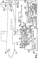
- an aircraft 10 having movable airfoils, namely, an aileron 12, an elevator. 14 and a rudder 16 located an rear edges respectively of a wing 18, and a horizontal stabilizer 20 and a vertical stabilizer 22 for controlling an attitude of the aircraft 10.
- the airfoils operate in response to control signals of a pilot in the cockpit 24, during manual control, and in response to signals of a control system 26 having a computer 28, during automatic control. Positions of the airfoils are communicated to the computer 28 by sensors 30, 32 and 34 which sense positions, respectively, of the aileron 12., the elevator 14 and the rudder 16.
- the aircraft 10 includes a jet engine 36 mounted on the wing 18 for propelling the aircraft 10 with a thrust provided on command by a signal of the pilot, during manual control, or by a signal of the computer 28 during automatic control.
- the engine 36 includes a combustion chamber 18 for burning fuel in air to obtain exhaust thrust which exits the engine 36 via an exhaust nozzle 40 to propel the aircraft 10, and also serves to drive a turbine 42 which, by means of a shaft 44, rotates a compressor fan 46 at the engine inlet. 48.
- the fan 46 forces air into the combustion chamber 38 and also forces air via a bypass duct 50 around the combustion chamber 38 to the nozzle 40.
- the engine 36 is provided with a thrust reverser 52 comprising four doors 54 of which two of the doors are shown in the drawing.
- Command signals developed within the computer 28 are applied to an actuation system for positioning the doors 54, one actuator 56 of the actuation system being shown in the drawing.
- Feedback signals describing the positions of each of the doors 54 are provided by a set of sensors in the form of switches 60 and 62 attached to a housing or frame of the engine 36 at the site of each door 54 to generate electrical signals indicating that, with respect to each door 54, the door is stowed, not stowed, or deployed.
- Mechanical connection of the switches to a door 54 is indicated by a dashed line 64.
- the switch 60 has two output poles. For each door 54, the switch 60 outputs an electric current from a suitable source (not shown) at one of two output poles to indicate a stow condition, and at the second output pole to indicate an unstowed condition, depending on the position of the switch.
- the switch 62 of each door 54 outputs a current to indicate a deployed condition.
- the signal currents provided by the switches 60 of each of the four doors 54 are combined to provide a single logic signal having either of two logic states, either a state of 1 or True, or a state of 0 or False.
- the signal currents provided by the respective output poles of the switches 60 of the four doors 54 are combined to provide logic signals indicating a stow condition and a not-stowed condition.
- the signal currents provided by the switches 62 are combined to provide a single logic signal indicating a deployed condition.
- the combining of the switch currents to provide the logic signals is accomplished, in practice, by the manner in which the switches 60 are wired together in parallel connection to provide the logic OR function, and the switches 62 are wired together in series connection to provide the logic AND function.
- the connections are represented by a logic unit 66 including OR gates 68 and 70, and an AND gate 72 which provide three system feedback signals and three redundant system feedback signals for the computer 28 designating status of the doors 54 as follows.
- a signal indicating that one, two, three, or all four doors 54 are stowed is provided by use of the OR gate 68 in the logic unit 66 wherein output currents of the first output pole of each of the switches 60 of all four doors 54 are applied to input terminals of the OR gate 68.
- a signal indicating that one, two, three, or all four doors 54 are unstowed is provided by use of the OR gate 70 wherein output currents of the second output pole of each of the switches 60 of all four doors 54 are applied to input terminals of the OR gate 70.
- a signal indicating that all four doors 54 are deployed is provided by use of the AND gate 72 wherein output currents of the switches 62 of all four doors 54 are applied to input terminals of the AND gate 72.
- Output signals of the three gates 68, 70 and 72 are applied to the computer 28.
- Backup switches 60A and 62A are connected to each of the doors 54 and output signals to the logic unit 66 for providing backup signals to the computer 28, the switches 60A and 62A functioning in the same fashion as the corresponding switches, respectively, 60 and 62.
- the logic unit 66 includes additional gates 68A, 70A and 72A for combining signals of the backup switches to provide the backup sensor signals for the computer 28.
- the logic unit 66 outputs six logic signals to the computer 28, namely, the stow signals S1 and S2 from the gates 68 and 68A, the not-stowed signals N1 and N2 from the gates 70 and 70A, and the deployed signals D1 and D2 from the gates 72 and 72A.
- the invention is to be demonstrated for the specific situation of evaluating the status of the thrust reverser 52, as has been noted above.
- the principles of the invention may be used to evaluate other aspects in the control of the aircraft 10 such as, by way of example, the status of fuel delivery.
- engine sensors 74, 76, 78 and 80 for providing to the computer 28, respectively, rotational speed in revolutions per minute (RPM) of the fan 46, temperature downstream of the fan 46, output pressure of the fan 46, and output temperature of the turbine 42.
- Fuel delivery is provided at 82 in the combustion chamber 38.
- the six logic signals outputted by the logic unit 66 can be viewed as a truth table for describing states of the control system 26 with respect to the status of the four thrust-reverser doors 54.
- Each of the signals has a logic state of 1 or True, or 0 or False.
- these six signals have the values, respectively, 0,0,1,1,1,1.
- these six signals have the values respectively, 1,1,0,0,0,0.
- the system 26 recognizes the foregoing four sets of logic signals which represent the possible positions of the thrust reverser 52, each set having six signals. If the logic unit 66 were to output a further set of signals such as 0,0,0,0,1,1, by way of example, which set is not part of the foregoing tabulation of four reference sets, the further set is a failure case, and indicates that there is a fault in the generation of one or more of the logic signals due to either a sensor problem or an actuation system problem or both.
- Case 1 differs from the failure case by a group of four parameters, namely, there are four logic signals N1, N2, D1 and D2 which differ between the failure set and the reference set.
- Case 2 differs from the failure case by a group of two parameters, the logic signals N1 and N2.
- Case 3 differs from the failure case by a group of four parameters, the logic signals S1, S2, D1 and D2.
- Case 4 differs from the failure case by a group of all six parameters, the logic signals S1, S2, N1, N2, D1 and D2.
- Each of the parameter groups is unique, in this particular example, in the sense that each parameter group has a set of logic signals differing from that of any other parameter group.
- the procedure of the invention addresses this question by use of probability by calculating the probability of occurrence of each of the parameter groups based on the commanded positions of the doors 54, as commanded by the computer 28 via signals applied to the actuators 56.
- the first situation (Command 1) requires the doors remain stowed 54 when the aircraft is in flight.
- the second situation (Command 2) requires a stowing of the doors 54 when the aircraft is on the ground.
- the third situation (Command 3) requires a deployment of the doors 54 when the aircraft is on the ground.
- Case 1 - Case 4 the invention proceeds by considering the probability of faulty operation of the sensor circuits producing the logic signals of the four parameter groups, namely, the four differing parameters of Case 1, the two differing parameters of Case 2, the four differing parameters of Case 1, and the six differing parameters of Case 4.
- the probability of faulty operation of the sensor circuits producing the logic signals of the four parameter groups namely, the four differing parameters of Case 1, the two differing parameters of Case 2, the four differing parameters of Case 1, and the six differing parameters of Case 4.
- the first parameter group (Case 1)
- Failures rates measured in terms of failures per flight hour, are very small typically, being on the order by way of example, of one part in a million or one part in a billion.
- the failure rates of switches and similar components are provided generally by the manufacturer of the component, as well as by analysis of repair service experienced, and this data is used to compute the probability of failure of the circuitry of a switch, such information being stored in a memory 84 of the computer 28.
- the probability of failure simultaneously of the sensor circuits producing the faults of any one of the foregoing parameter groups, such as the first parameter group of logic signals N1, N2, D1 and D2, is attained in accordance with well-known rules of probability for combining the probabilities of failure of the circuits of the switches 60, 60A, 62, and 62A. Similar combinations of the probabilities of the switch circuits are employed for calculation of the probabilities of occurrence of the other parameter groups.
- the probability of occurrence of one of the parameter groups is based also on the possibility of a failure in the actuation system including hydraulic and/or mechanical and/or electrical portions which may be present in the implementation of the actuation system.
- the probability of the four actuators 56 acting in a prescribed fashion to position the four doors 54 depends on the command situation, namely, Command 1, Command 2 or Command 3. These probabilities are calculated in a fashion analogous to that of the sensor circuits, and are based on failure rates of the individual components of each mechanical circuit of an actuator.
- the probability of occurrence of a parameter group is the joint probability of failure of sensor circuitry and of actuation system circuitry. The joint probability is obtained by multiplying together the failure probability of the sensor circuitry by the failure probability of the mechanical circuitry.
- the various probabilities are compared, in a manner to be described, to select the most probable system state which is presumed to be the actual system state for purposes of controlling the aircraft 10.
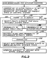
- Fig. 2 shows the procedure of the invention.
- the procedure begins at block 86 in which the computer 28 scans the sensor logic signals of the logic unit 66 and notes the present actuator command to the actuators 56.
- the computer 28 compares the present set of sensor signals with the set of reference sensor signals corresponding to the system state as established by the actuator command, the reference signals having been stored previously in the computer memory 84. If a match is obtained at block 90, the procedure advances to block 92 wherein the aircraft 10 is operated in accord with the actual system state.
- the procedure advances to block 94 in which the present set of sensor logic signals are evaluated for each possible system state by comparing the present sensor logic signals to each of the reference sets of sensor logic signals to select the faulty signals for each parameter group.
- the two probabilities are multiplied together at block 100 to obtain the joint probability of the occurrence of each parameter group of faulty signals.
- the various probabilities of block 100 are normalized at block 102. Normalization is accomplished by summing together the values of the individual probabilities to obtain a sum, and then by dividing each of the probabilities by the sum.
- each parameter group is associated with a specific system state and, accordingly, the state of the most-likely parameter group is taken as the actual system state.
- the procedure then advances to block 92 for operation of the aircraft 10 in accordance with the actual system state.
Landscapes
- Engineering & Computer Science (AREA)
- Physics & Mathematics (AREA)
- General Physics & Mathematics (AREA)
- Automation & Control Theory (AREA)
- Aviation & Aerospace Engineering (AREA)
- Radar, Positioning & Navigation (AREA)
- Remote Sensing (AREA)
- Feedback Control In General (AREA)
Applications Claiming Priority (2)
| Application Number | Priority Date | Filing Date | Title |
|---|---|---|---|
| US78744991A | 1991-11-04 | 1991-11-04 | |
| US787449 | 1991-11-04 |
Publications (2)
| Publication Number | Publication Date |
|---|---|
| EP0541326A2 true EP0541326A2 (de) | 1993-05-12 |
| EP0541326A3 EP0541326A3 (en) | 1993-06-09 |
Family
ID=25141513
Family Applications (1)
| Application Number | Title | Priority Date | Filing Date |
|---|---|---|---|
| EP19920310046 Withdrawn EP0541326A3 (en) | 1991-11-04 | 1992-11-03 | Determination of control system status |
Country Status (1)
| Country | Link |
|---|---|
| EP (1) | EP0541326A3 (de) |
Cited By (8)
| Publication number | Priority date | Publication date | Assignee | Title |
|---|---|---|---|---|
| WO1999006892A1 (en) * | 1997-07-29 | 1999-02-11 | Skf Condition Monitoring, Inc. | Method and system for fast probe failure determination |
| EP0830647A4 (de) * | 1995-06-07 | 2000-04-26 | Aurora Flight Sciences Corp | Automatisches fehlertolerantes steuerungssystem unter verwendung analytischer redundanz |
| WO2002088850A1 (en) * | 2001-04-26 | 2002-11-07 | Abb As | Method for detecting and correcting sensor failure in oil and gas production system |
| EP1217333A3 (de) * | 2000-12-07 | 2003-05-14 | EIM Company, Inc. | Positionskodiervorrichtung |
| WO2003042928A3 (en) * | 2001-11-13 | 2003-11-13 | Goodrich Pump & Engine Control | Fault management system for gas turbine engines |
| EP2874065A3 (de) * | 2013-11-15 | 2015-10-21 | Ultra Electronics Limited | Verfahren und Vorrichtung zur Steuerung von Flugzeugsteuerungssystemen |
| US20210262399A1 (en) * | 2020-02-24 | 2021-08-26 | General Electric Company | Autonomous safety mode for distributed conrtol of turbomachines |
| CN113602507A (zh) * | 2021-08-26 | 2021-11-05 | 中国商用飞机有限责任公司 | 一种自动反推控制系统和方法 |
Family Cites Families (2)
| Publication number | Priority date | Publication date | Assignee | Title |
|---|---|---|---|---|
| US3845370A (en) * | 1973-08-10 | 1974-10-29 | Ibm | Credibility testing in sampled-data systems |
| JPS60167007A (ja) * | 1984-02-10 | 1985-08-30 | Hitachi Ltd | プラントの故障原因推定方式 |
-
1992
- 1992-11-03 EP EP19920310046 patent/EP0541326A3/en not_active Withdrawn
Cited By (12)
| Publication number | Priority date | Publication date | Assignee | Title |
|---|---|---|---|---|
| EP0830647A4 (de) * | 1995-06-07 | 2000-04-26 | Aurora Flight Sciences Corp | Automatisches fehlertolerantes steuerungssystem unter verwendung analytischer redundanz |
| WO1999006892A1 (en) * | 1997-07-29 | 1999-02-11 | Skf Condition Monitoring, Inc. | Method and system for fast probe failure determination |
| US6199422B1 (en) | 1997-07-29 | 2001-03-13 | Skf Condition Monitoring, Inc. | Method and system for fast probe failure determination |
| EP1217333A3 (de) * | 2000-12-07 | 2003-05-14 | EIM Company, Inc. | Positionskodiervorrichtung |
| WO2002088850A1 (en) * | 2001-04-26 | 2002-11-07 | Abb As | Method for detecting and correcting sensor failure in oil and gas production system |
| WO2003042928A3 (en) * | 2001-11-13 | 2003-11-13 | Goodrich Pump & Engine Control | Fault management system for gas turbine engines |
| US6843060B2 (en) | 2001-11-13 | 2005-01-18 | Goodrich Pump & Engine Control Systems, Inc. | Fault management system for gas turbine engines |
| EP2874065A3 (de) * | 2013-11-15 | 2015-10-21 | Ultra Electronics Limited | Verfahren und Vorrichtung zur Steuerung von Flugzeugsteuerungssystemen |
| US20210262399A1 (en) * | 2020-02-24 | 2021-08-26 | General Electric Company | Autonomous safety mode for distributed conrtol of turbomachines |
| US11661895B2 (en) * | 2020-02-24 | 2023-05-30 | General Electric Comapny | Autonomous safety mode for distributed control of turbomachines |
| CN113602507A (zh) * | 2021-08-26 | 2021-11-05 | 中国商用飞机有限责任公司 | 一种自动反推控制系统和方法 |
| CN113602507B (zh) * | 2021-08-26 | 2022-08-02 | 中国商用飞机有限责任公司 | 一种自动反推控制系统和方法 |
Also Published As
| Publication number | Publication date |
|---|---|
| EP0541326A3 (en) | 1993-06-09 |
Similar Documents
| Publication | Publication Date | Title |
|---|---|---|
| EP0110885B1 (de) | Autopilotflugrichtungssystem | |
| US5001638A (en) | Integrated aircraft air data system | |
| US4032757A (en) | Control apparatus | |
| EP1756685B1 (de) | Verfahren zum testen eines kombinierten dynamischen positionierungs- und leistungsverwaltungssystems | |
| US6578794B1 (en) | Methods and systems for jet engine overthrust protection | |
| EP0244344B1 (de) | Verteiltes Flugdatenzustandsbewertungssystem und Verfahren | |
| EP1960855B1 (de) | Verfahren und system zur prüfung eines energieverwaltungssystems eines seefahrzeugs | |
| EP0653690B1 (de) | Doppelsteuerung mit Mittelwertbildung und Austausch von zwei Sensoren | |
| US3851157A (en) | Self-correcting feedback control system | |
| CN1123488C (zh) | 控制舱压的控制装置、舱压控制系统以及方法 | |
| EP1444658B1 (de) | Fehlerverwaltungssystem für gasturbinentriebwerke | |
| US10822113B2 (en) | Actuator monitoring system using inertial sensors | |
| GB2436366A (en) | Monitoring Gas Turbine Engines | |
| EP0541326A2 (de) | Bestimmung des Zustandes eines Steuerungssystems | |
| US8881529B2 (en) | Modular fuel supply device for a gas turbine including a fuel supply device having an integrated control device | |
| JP3965243B2 (ja) | 操縦装置 | |
| EP4019396B1 (de) | System und verfahren zur erkennung von propellerfehlfunktionen | |
| EP1101026A1 (de) | Drehzahlanpassungssystem für ein gasturbinentriebwerk um schubüberschuss zu kompensieren | |
| CN113401337B (zh) | 飞行器及其控制方法、控制装置 | |
| CN111382500B (zh) | 一种航空发动机涡轮增压系统的安全性分析验证方法 | |
| US6393353B1 (en) | Self-testable architecture for overspeed limitation and cutoff systems when the turbojet stops | |
| JP2877912B2 (ja) | 内燃機関の電子制御装置 | |
| EP1837506A2 (de) | Überwachung von Gasturbinentriebwerken | |
| STEWART et al. | Flight-testing of the self-repairing flight control system using theF-15 highly integrated digital electronic control flight research facility | |
| RU2810867C1 (ru) | Способ защиты газотурбинного двигателя от помпажа компрессора электронной двухканальной системой автоматического управления |
Legal Events
| Date | Code | Title | Description |
|---|---|---|---|
| PUAI | Public reference made under article 153(3) epc to a published international application that has entered the european phase |
Free format text: ORIGINAL CODE: 0009012 |
|
| PUAL | Search report despatched |
Free format text: ORIGINAL CODE: 0009013 |
|
| AK | Designated contracting states |
Kind code of ref document: A2 Designated state(s): DE FR GB |
|
| AK | Designated contracting states |
Kind code of ref document: A3 Designated state(s): DE FR GB |
|
| 18D | Application deemed to be withdrawn |
Effective date: 19931210 |