EP0541336A1 - Hydraulisches Steuerungssystem - Google Patents
Hydraulisches Steuerungssystem Download PDFInfo
- Publication number
- EP0541336A1 EP0541336A1 EP92310069A EP92310069A EP0541336A1 EP 0541336 A1 EP0541336 A1 EP 0541336A1 EP 92310069 A EP92310069 A EP 92310069A EP 92310069 A EP92310069 A EP 92310069A EP 0541336 A1 EP0541336 A1 EP 0541336A1
- Authority
- EP
- European Patent Office
- Prior art keywords
- pilot
- valve
- pressure
- actuator
- spool
- Prior art date
- Legal status (The legal status is an assumption and is not a legal conclusion. Google has not performed a legal analysis and makes no representation as to the accuracy of the status listed.)
- Granted
Links
Images



Classifications
-
- F—MECHANICAL ENGINEERING; LIGHTING; HEATING; WEAPONS; BLASTING
- F15—FLUID-PRESSURE ACTUATORS; HYDRAULICS OR PNEUMATICS IN GENERAL
- F15B—SYSTEMS ACTING BY MEANS OF FLUIDS IN GENERAL; FLUID-PRESSURE ACTUATORS, e.g. SERVOMOTORS; DETAILS OF FLUID-PRESSURE SYSTEMS, NOT OTHERWISE PROVIDED FOR
- F15B13/00—Details of servomotor systems ; Valves for servomotor systems
- F15B13/02—Fluid distribution or supply devices characterised by their adaptation to the control of servomotors
- F15B13/04—Fluid distribution or supply devices characterised by their adaptation to the control of servomotors for use with a single servomotor
- F15B13/0401—Valve members; Fluid interconnections therefor
- F15B13/0405—Valve members; Fluid interconnections therefor for seat valves, i.e. poppet valves
Definitions
- This invention relates to hydraulic control systems and particularly to hydraulic control systems for controlling the movement of linear or rotary actuators.
- This invention relates to hydraulic systems for controlling a plurality of actuators such as hydraulic cylinders which are found, for example, in earth moving equipment such as excavators and cranes.
- actuators such as hydraulic cylinders which are found, for example, in earth moving equipment such as excavators and cranes.
- it is conventional to provide a pilot operated control valve for each actuator which is controlled by a manually or fluid or electric operated controller through a pilot hydraulic circuit.
- the control valve functions to supply hydraulic fluid to the actuator to control the speed and direction of operation of the actuator.
- a hydraulic control system comprising a hydraulic actuator, a pilot controller and a pump.
- the actuator includes a movable element and a pair of openings adapted to function alternately as inlets or outlets for moving the element in opposite directions.
- the pilot controller supplies fluid to the system at pilot pressure and the pump supplies fluid at pump pressure to the actuator.
- the control system includes a line adapted for connected to each of the openings and a meter-out valve associated with each of the lines for controlling fluid flow from the actuator.
- the meter-out valves are each selectively pilot operated by pilot pressure from the pilot controller.
- a meter-in valve means controls fluid flow from the pump to the actuator and is selectively operable by pilot pressure from the pilot controller.
- a hydraulic control system for controlling a hydraulic actuator comprising a pump for supplying fluid to the actuator and a directional valve for controlling the flow of fluid to the actuator.
- the directional valve includes a poppet piston that together with the housing provides a variable orifice.
- the position of the poppet piston is controlled by a pilot flow controlled by a pilot valve which may be controlled by a solenoid controller.
- the flow out of the pilot valve is directed to a position downstream from the directional valve.
- a pressure compensator is provided between the inlet to the directional valve and maintains a constant pilot flow each pilot valve position regardless of the pressure, differential of the directional valve.
- the pressure of fluid being applied to the actuator by the directional valve is also sensed and caused to produce a force opposing the opening force applied to the pilot valve to result in a smooth and accurate control of the load.
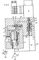
- Fig. 2 is a part sectional schematic view of a modified form of hydraulic control system.
- Fig. 2A is a fragmentary view of an enlarged scale of a portion of Fig. 2.
- Fig. 3 is a sectional schematic of a further modified form of hydraulic control system.
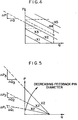
- Fig. 4 is a diagram of curves of pressure versus flow for hydraulic control system embodying the invention.
- Fig. 5 is a diagram of curves of pressure versus flow for a hydraulic system as shown in Fig. 1.
- Fig. 6 is a part sectional view of a prior art hydraulic control system.
- a hydraulic control system embodying the invention comprises a pump P that is adapted to supply fluid to an inlet of an actuator A.
- the pump P directs fluid to the inlet 10 of a directional valve 11 that includes a sleeve 12 surrounding a poppet piston 13 that has a plurality of axial slots 14 therein.
- the sleeve 12 includes passages 15 that supply the fluid from the pump to the grooves 14 so that as the piston 13 moves a variable orifice is provided.
- the poppet piston 13 is movable to a maximum closed position defined by a seat 16.
- the poppet piston 13 is movable to a maximum open position defined by the upper valve body.
- Poppet piston 13 includes an upper portion having a larger diameter than the lower portion.
- the valve 11 is of the type shown in the aforementioned U.S. Patents Nos. 4,535,809 and 4,964,611, incorporated herein by reference.
- a portion of the fluid at the inlet 10 is provided by slots 14 to a pilot valve 18 through a passage 17 from the space 17a above the poppet valve 13 and through a line 17b to the pilot valve 18 that includes a pilot spool 19 controlling the flow past an orifice 20 by a conical portion 21 engaging a seat 22.
- the position of the pilot spool 19 is controlled by a pilot controller herein shown as a variable position solenoid S.
- a pilot controller herein shown as a variable position solenoid S.
- an electrical signal provides a magnetic field that determines the force on the spool 19 urging the pilot spool to open orifice 20.
- the spool 19 is placed under a yielding force which can be opposed, as presently described.
- a manual controller could be used, but it would be required that a spring be positioned between the manual controller and the end of the spool 19. Fluid moving past the orifice 20 communicates with a outlet 23 through a line 24.
- a feedback piston 30 is provided in the spring chamber 31 of the pilot valve 18 and the end of the piston 30 communicates through a line 32 to line 24.
- the feedback piston 30 senses the outlet pressure from the directional valve 11 through line 32 and applies a force opposing the force of the solenoid S and thereby provide for a smooth and accurate control of the movement of the actuator A.
- the feedback spool or pin 30a senses the pressure in the line 24 through openings 26 and 27 in the pilot spool 19 to thereby provide an opposing force to the force from the solenoid S on the pilot spool 19.
- the feedback is achieved by having a reduced portion 40 of the spool 18 such that a force is provided opposing the movement of the pilot spool.
- the manner in which the variation in diameter affects the amount of dampening is shown by reference to Fig. 6.
- the several curves showing the amount of dampening is varied by the diameter and, in turn, the amount of force that is opposing movement of the pilot valve.
Landscapes
- Engineering & Computer Science (AREA)
- Physics & Mathematics (AREA)
- Fluid Mechanics (AREA)
- Mechanical Engineering (AREA)
- General Engineering & Computer Science (AREA)
- Fluid-Pressure Circuits (AREA)
- Operation Control Of Excavators (AREA)
- Servomotors (AREA)
Applications Claiming Priority (2)
| Application Number | Priority Date | Filing Date | Title |
|---|---|---|---|
| US787260 | 1991-11-04 | ||
| US07/787,260 US5170692A (en) | 1991-11-04 | 1991-11-04 | Hydraulic control system |
Publications (2)
| Publication Number | Publication Date |
|---|---|
| EP0541336A1 true EP0541336A1 (de) | 1993-05-12 |
| EP0541336B1 EP0541336B1 (de) | 1996-01-10 |
Family
ID=25140910
Family Applications (1)
| Application Number | Title | Priority Date | Filing Date |
|---|---|---|---|
| EP92310069A Expired - Lifetime EP0541336B1 (de) | 1991-11-04 | 1992-11-03 | Hydraulisches Steuerungssystem |
Country Status (6)
| Country | Link |
|---|---|
| US (1) | US5170692A (de) |
| EP (1) | EP0541336B1 (de) |
| JP (1) | JPH05263804A (de) |
| BR (1) | BR9204272A (de) |
| CA (1) | CA2082039A1 (de) |
| DE (1) | DE69207556T2 (de) |
Families Citing this family (14)
| Publication number | Priority date | Publication date | Assignee | Title |
|---|---|---|---|---|
| DE69626537T2 (de) * | 1995-12-15 | 2004-02-12 | Parker Hannifin Plc, Hemel Hempstead | Steuerventile |
| KR20010071204A (ko) | 1999-03-04 | 2001-07-28 | 세구치 류이치 | 유압회로장치 |
| JP3583643B2 (ja) * | 1999-03-05 | 2004-11-04 | 日立建機株式会社 | 油圧回路装置 |
| WO2001009513A1 (en) * | 1999-07-30 | 2001-02-08 | Crs Services, Inc. | Hydraulic pump manifold |
| US6691604B1 (en) | 1999-09-28 | 2004-02-17 | Caterpillar Inc | Hydraulic system with an actuator having independent meter-in meter-out control |
| US6557822B1 (en) | 2000-11-21 | 2003-05-06 | Caterpillar Inc. | Dynamically stable flow amplifying poppet valve |
| US6814409B2 (en) | 2001-04-12 | 2004-11-09 | A-Dec, Inc. | Hydraulic drive system |
| US8256739B2 (en) * | 2008-12-22 | 2012-09-04 | Husco International, Inc. | Poppet valve operated by an electrohydraulic poppet pilot valve |
| US8684037B2 (en) * | 2009-08-05 | 2014-04-01 | Eaton Corportion | Proportional poppet valve with integral check valve |
| US8291934B2 (en) * | 2010-01-20 | 2012-10-23 | Eaton Corporation | Proportional valve assembly |
| US8770543B2 (en) | 2011-07-14 | 2014-07-08 | Eaton Corporation | Proportional poppet valve with integral check valves |
| US9198349B2 (en) * | 2013-07-12 | 2015-12-01 | Deere & Company | Articulated harvesting head ground force control circuit |
| DE102016006545A1 (de) * | 2016-05-25 | 2017-11-30 | Hydac System Gmbh | Ventilvorrichtung |
| IT201700096057A1 (it) * | 2017-08-25 | 2019-02-25 | Bosch Gmbh Robert | Unita' valvola di ritegno comandata elettricamente |
Citations (3)
| Publication number | Priority date | Publication date | Assignee | Title |
|---|---|---|---|---|
| EP0023416A2 (de) * | 1979-07-26 | 1981-02-04 | Vickers Incorporated | Hydraulisches Ventil |
| EP0291140A2 (de) * | 1987-05-14 | 1988-11-17 | Hitachi Construction Machinery Co., Ltd. | Durchflusssteuerventil |
| EP0297682A2 (de) * | 1987-06-30 | 1989-01-04 | Hitachi Construction Machinery Co., Ltd. | Hydraulisches Antriebssystem |
Family Cites Families (7)
| Publication number | Priority date | Publication date | Assignee | Title |
|---|---|---|---|---|
| US3972267A (en) * | 1975-03-05 | 1976-08-03 | Caterpillar Tractor Co. | Overruning load control for hydraulic jacks |
| JPS6024961Y2 (ja) * | 1980-05-30 | 1985-07-26 | 焼結金属工業株式会社 | シリンダ駆動装置 |
| US4407122A (en) * | 1981-05-18 | 1983-10-04 | Vickers, Incorporated | Power transmission |
| US4466336A (en) * | 1982-02-08 | 1984-08-21 | Lakeland Hydraulics, Inc. | Control valve for hydraulic motor apparatus |
| DE3705170C1 (de) * | 1987-02-18 | 1988-08-18 | Heilmeier & Weinlein | Hydraulische Steuervorrichtung |
| DE3812300C1 (de) * | 1988-04-13 | 1989-03-02 | Hydromatik Gmbh, 7915 Elchingen, De | |
| SE462349B (sv) * | 1988-11-15 | 1990-06-11 | Bahco Hydrauto Ab | Tryckmediumventil |
-
1991
- 1991-11-04 US US07/787,260 patent/US5170692A/en not_active Expired - Lifetime
-
1992
- 1992-11-03 DE DE69207556T patent/DE69207556T2/de not_active Expired - Fee Related
- 1992-11-03 EP EP92310069A patent/EP0541336B1/de not_active Expired - Lifetime
- 1992-11-03 CA CA002082039A patent/CA2082039A1/en not_active Abandoned
- 1992-11-04 JP JP4295197A patent/JPH05263804A/ja active Pending
- 1992-11-04 BR BR929204272A patent/BR9204272A/pt not_active Application Discontinuation
Patent Citations (3)
| Publication number | Priority date | Publication date | Assignee | Title |
|---|---|---|---|---|
| EP0023416A2 (de) * | 1979-07-26 | 1981-02-04 | Vickers Incorporated | Hydraulisches Ventil |
| EP0291140A2 (de) * | 1987-05-14 | 1988-11-17 | Hitachi Construction Machinery Co., Ltd. | Durchflusssteuerventil |
| EP0297682A2 (de) * | 1987-06-30 | 1989-01-04 | Hitachi Construction Machinery Co., Ltd. | Hydraulisches Antriebssystem |
Also Published As
| Publication number | Publication date |
|---|---|
| BR9204272A (pt) | 1993-05-11 |
| US5170692A (en) | 1992-12-15 |
| DE69207556T2 (de) | 1996-05-15 |
| EP0541336B1 (de) | 1996-01-10 |
| CA2082039A1 (en) | 1993-05-05 |
| JPH05263804A (ja) | 1993-10-12 |
| DE69207556D1 (de) | 1996-02-22 |
Similar Documents
| Publication | Publication Date | Title |
|---|---|---|
| EP0541336B1 (de) | Hydraulisches Steuerungssystem | |
| US8726646B2 (en) | Hydraulic system having multiple actuators and an associated control method | |
| EP0900962B1 (de) | Elektromagnetisch betätigtes Steuerventil und hydraulisches Steuersystem unter Verwendung desselben | |
| KR100432381B1 (ko) | 전기-유압식비례제어밸브조립체 | |
| US6745992B2 (en) | Pilot operated control valve having a poppet with integral pressure compensating mechanism | |
| US6467264B1 (en) | Hydraulic circuit with a return line metering valve and method of operation | |
| KR100576930B1 (ko) | 유압모터로의 유체 흐름을 조절하기 위한 세개의 전동유압밸브를 가지는 유압 시스템 | |
| JP4653091B2 (ja) | 少なくとも2つの流体圧コンシューマに圧力手段を供給するための制御装置および方法 | |
| US6318079B1 (en) | Hydraulic control valve system with pressure compensated flow control | |
| EP0085962B1 (de) | Hydraulisches Steuersystem,insbesondere für schwenkende Lasten | |
| CA1169334A (en) | Power transmission | |
| EP0953776B1 (de) | Elektromagnetisch betätigte Ventileinheit mit zwei Kolbenschiebern | |
| US6073652A (en) | Pilot solenoid control valve with integral pressure sensing transducer | |
| EP0066150A2 (de) | Servogesteuertes Wegeventil mit variabeler Verstärkung | |
| EP0128740A1 (de) | Druckregler | |
| EP0427865B1 (de) | Hydraulische antriebsanordnung einer bauvorrichtung | |
| JPH0364744B2 (de) | ||
| JPH0674204A (ja) | 複数の消費器のための油圧式の制御装置 | |
| US6148856A (en) | Control valve | |
| EP0116739A2 (de) | Hydraulisches Ventil | |
| US5027856A (en) | Electrohydraulic signal converter | |
| JPH0359307B2 (de) | ||
| EP0280808A1 (de) | Proportionalventile mit elektrohydraulischer Regelung | |
| GB2328524A (en) | An electro hydraulic proportional control valve assembly | |
| JPS6134927Y2 (de) |
Legal Events
| Date | Code | Title | Description |
|---|---|---|---|
| PUAI | Public reference made under article 153(3) epc to a published international application that has entered the european phase |
Free format text: ORIGINAL CODE: 0009012 |
|
| AK | Designated contracting states |
Kind code of ref document: A1 Designated state(s): DE FR GB IT SE |
|
| 17P | Request for examination filed |
Effective date: 19930910 |
|
| 17Q | First examination report despatched |
Effective date: 19950302 |
|
| GRAA | (expected) grant |
Free format text: ORIGINAL CODE: 0009210 |
|
| AK | Designated contracting states |
Kind code of ref document: B1 Designated state(s): DE FR GB IT SE |
|
| ITF | It: translation for a ep patent filed | ||
| REF | Corresponds to: |
Ref document number: 69207556 Country of ref document: DE Date of ref document: 19960222 |
|
| ET | Fr: translation filed | ||
| PLBE | No opposition filed within time limit |
Free format text: ORIGINAL CODE: 0009261 |
|
| 26N | No opposition filed | ||
| REG | Reference to a national code |
Ref country code: GB Ref legal event code: IF02 |
|
| PGFP | Annual fee paid to national office [announced via postgrant information from national office to epo] |
Ref country code: GB Payment date: 20051004 Year of fee payment: 14 |
|
| PGFP | Annual fee paid to national office [announced via postgrant information from national office to epo] |
Ref country code: FR Payment date: 20051104 Year of fee payment: 14 |
|
| PGFP | Annual fee paid to national office [announced via postgrant information from national office to epo] |
Ref country code: SE Payment date: 20051107 Year of fee payment: 14 |
|
| PGFP | Annual fee paid to national office [announced via postgrant information from national office to epo] |
Ref country code: DE Payment date: 20051130 Year of fee payment: 14 |
|
| PG25 | Lapsed in a contracting state [announced via postgrant information from national office to epo] |
Ref country code: SE Free format text: LAPSE BECAUSE OF NON-PAYMENT OF DUE FEES Effective date: 20061104 |
|
| PGFP | Annual fee paid to national office [announced via postgrant information from national office to epo] |
Ref country code: IT Payment date: 20061130 Year of fee payment: 15 |
|
| PG25 | Lapsed in a contracting state [announced via postgrant information from national office to epo] |
Ref country code: DE Free format text: LAPSE BECAUSE OF NON-PAYMENT OF DUE FEES Effective date: 20070601 |
|
| EUG | Se: european patent has lapsed | ||
| GBPC | Gb: european patent ceased through non-payment of renewal fee |
Effective date: 20061103 |
|
| REG | Reference to a national code |
Ref country code: FR Ref legal event code: ST Effective date: 20070731 |
|
| PG25 | Lapsed in a contracting state [announced via postgrant information from national office to epo] |
Ref country code: GB Free format text: LAPSE BECAUSE OF NON-PAYMENT OF DUE FEES Effective date: 20061103 |
|
| PG25 | Lapsed in a contracting state [announced via postgrant information from national office to epo] |
Ref country code: FR Free format text: LAPSE BECAUSE OF NON-PAYMENT OF DUE FEES Effective date: 20061130 |
|
| PG25 | Lapsed in a contracting state [announced via postgrant information from national office to epo] |
Ref country code: IT Free format text: LAPSE BECAUSE OF NON-PAYMENT OF DUE FEES Effective date: 20071103 |