EP0541348B1 - Seilklemme - Google Patents
Seilklemme Download PDFInfo
- Publication number
- EP0541348B1 EP0541348B1 EP92310093A EP92310093A EP0541348B1 EP 0541348 B1 EP0541348 B1 EP 0541348B1 EP 92310093 A EP92310093 A EP 92310093A EP 92310093 A EP92310093 A EP 92310093A EP 0541348 B1 EP0541348 B1 EP 0541348B1
- Authority
- EP
- European Patent Office
- Prior art keywords
- rope
- members
- link
- attitude
- clutch according
- Prior art date
- Legal status (The legal status is an assumption and is not a legal conclusion. Google has not performed a legal analysis and makes no representation as to the accuracy of the status listed.)
- Expired - Lifetime
Links
Images


Classifications
-
- F—MECHANICAL ENGINEERING; LIGHTING; HEATING; WEAPONS; BLASTING
- F16—ENGINEERING ELEMENTS AND UNITS; GENERAL MEASURES FOR PRODUCING AND MAINTAINING EFFECTIVE FUNCTIONING OF MACHINES OR INSTALLATIONS; THERMAL INSULATION IN GENERAL
- F16G—BELTS, CABLES, OR ROPES, PREDOMINANTLY USED FOR DRIVING PURPOSES; CHAINS; FITTINGS PREDOMINANTLY USED THEREFOR
- F16G11/00—Means for fastening cables or ropes to one another or to other objects; Caps or sleeves for fixing on cables or ropes
- F16G11/10—Quick-acting fastenings; Clamps holding in one direction only
- F16G11/101—Quick-acting fastenings; Clamps holding in one direction only deforming the cable by moving a part of the fastener
-
- Y—GENERAL TAGGING OF NEW TECHNOLOGICAL DEVELOPMENTS; GENERAL TAGGING OF CROSS-SECTIONAL TECHNOLOGIES SPANNING OVER SEVERAL SECTIONS OF THE IPC; TECHNICAL SUBJECTS COVERED BY FORMER USPC CROSS-REFERENCE ART COLLECTIONS [XRACs] AND DIGESTS
- Y10—TECHNICAL SUBJECTS COVERED BY FORMER USPC
- Y10T—TECHNICAL SUBJECTS COVERED BY FORMER US CLASSIFICATION
- Y10T24/00—Buckles, buttons, clasps, etc.
- Y10T24/39—Cord and rope holders
- Y10T24/3936—Pivoted part
- Y10T24/394—Cam lever
- Y10T24/3949—Link-connected parallel jaws
-
- Y—GENERAL TAGGING OF NEW TECHNOLOGICAL DEVELOPMENTS; GENERAL TAGGING OF CROSS-SECTIONAL TECHNOLOGIES SPANNING OVER SEVERAL SECTIONS OF THE IPC; TECHNICAL SUBJECTS COVERED BY FORMER USPC CROSS-REFERENCE ART COLLECTIONS [XRACs] AND DIGESTS
- Y10—TECHNICAL SUBJECTS COVERED BY FORMER USPC
- Y10T—TECHNICAL SUBJECTS COVERED BY FORMER US CLASSIFICATION
- Y10T24/00—Buckles, buttons, clasps, etc.
- Y10T24/39—Cord and rope holders
- Y10T24/3936—Pivoted part
- Y10T24/394—Cam lever
- Y10T24/3951—Dual cam
-
- Y—GENERAL TAGGING OF NEW TECHNOLOGICAL DEVELOPMENTS; GENERAL TAGGING OF CROSS-SECTIONAL TECHNOLOGIES SPANNING OVER SEVERAL SECTIONS OF THE IPC; TECHNICAL SUBJECTS COVERED BY FORMER USPC CROSS-REFERENCE ART COLLECTIONS [XRACs] AND DIGESTS
- Y10—TECHNICAL SUBJECTS COVERED BY FORMER USPC
- Y10T—TECHNICAL SUBJECTS COVERED BY FORMER US CLASSIFICATION
- Y10T24/00—Buckles, buttons, clasps, etc.
- Y10T24/39—Cord and rope holders
- Y10T24/3936—Pivoted part
- Y10T24/3956—Jaws locked together by cam, wedge, lever, or screw
Definitions
- the present invention relates to a rope clutch - also known as a rope clamp - for use in sailing boats and the like.
- the present invention provides a rope clutch having an adaptable link so as to ensure as far as possible that the user of the rope clutch always initiates release at adequate mechanical advantage.
- a rope clutch has a variable toggle linkage between a release actuating lever and its clamping mechanism with a link engaging between the handle and the member(s) by an abutment and an aperture, an edge of which defines a plurality of locations at which it may engage an abutment.
- the aperture is preferably in the link and the abutment a cross pin associated with the pivotable member(s).
- the working range of clutch in relation to rope diameters is less constrained by the need for the user to have adequate mechanical advantage when initiating release; by adoption of the appropriate location, a sufficient amount of toggle action and of initial mechanical advantage can be obtained over a wide range of rope sizes, since the adoption allows the nearest possible approach to alignment between the abutment location and the axes of the handle axis and link pivot axis, over a range of clamping member angles.
- the rope clutch comprises a plurality of clamping members each having an opening through which the rope is to pass.
- the clamping members can pivot about fixed coplanar and parallel axes at their bases and are preferably pivotally joined at the top to a connecting element that ensures that the clamping members remain parallel to each other and a fixed pitch apart.
- the openings through the clamping members are preferably obliquely angled with respect to the members. In any case, clamping action is produced by a load on the rope pulling the clamping members into an attitude wherein it is trapped in a zig-zag in and between the members.
- a link may have two or more parallel link members to provide the toggle action between the lever and the clamping mechanism.
- a means between the link member and the release handle may be included to ensure the release handle and link tend to move in unison until the correct location is adopted. This may be friction between them.
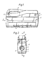
- the rope clutch 1 has side plates 2,3 trapping between them rings 4,5 defining a rope path through the clutch.
- Clamping members 7 are pivoted on stub axles 6 and define a variable-width through passage 8 in the path, as will be described in more detail later.
- a handle 9 is also pivoted between the side plates and is manually pivotable in upwards rotation (clockwise in Figure 1) to actuate the clamping members.
- the handle 9 is preferably of a plastics material moulded with an open cellular undersurface.
- Screws 10 hold the side plates 2,3 together towards their upper edge; at their lower edge they are held together by claws 11 of plates 12,13 ( Figure 3) engaging in holes in a floor surface 14 of the respective side plates.
- Claws 11 preferably have wedging side surfaces (not shown) to clamp the side plates together as the plates 12,13 are drawn downwardly.
- each clamping member 7 has a forked lower end terminating in outwardly-directed stub axles 6 to engage pivotally with apertures in the side plates and define for the members a plurality of parallel pivotal axes.
- Each member 7 has at its upper portion an aperture 15 - see the two sectioned members 7 in Figure 3.
- the apertures are closed to both lateral sides of the members 7.
- Each aperture has upper and lower surfaces 16,17 inclined at an angle to the general plane 18 of the member, here at about 65-70°. However the surfaces as seen in section are somewhat curved and are radiused at 19,20 where they would intersect the faces of the members.
- members 7 At their upper ends members 7 have outwardly-directed stub axles 21. These are engaged by connecting plates 22, one on each lateral side of the members 7, so as to cause all the members to pivot in unison and maintain their planes 18 parallel.
- connecting plates 22 Projecting from the laterally outer sides of connecting plates 22 is a cross pin 23, preferably formed from a rolled cylinder of sprung steel. This is to act as an abutment in a variable toggle mechanism which links the actuating lever, the handle 9, to the clamping mechanism provided by the members 7.
- the handle 9 is pivoted between the side plates at axle 24.
- the toggle mechanism has a pivot axle 25 penetrating the handle and on which link plates 26, lying laterally outside of the handle 9 and the connecting plates 22 can pivot relative to the handle 9.
- the plates 26 have frictional drag resisting that pivoting, preferably provided by friction or spring washers (not shown) entrapped between the plates 26 and the sides of the handle.
- Each plate 26 has a generally triangular aperture 27 in it. At its edge 28 remote from the pivot 25 each aperture has a plurality of engagement locations 29 defined by scallops. The distance of the various scallops from the pivot 25 is different, the lowest scallops being nearest and the highest furthest from it.
- the abutment 23 projects into the aperture 27 and is for engagement with its edges, and in particular with the locations 29 on edge 28.
- Figure 3 also shows how side plates 2,3 have reinforcement bosses 30,31 around the pivot axis 24 and the axes of the stub axles 6, and strengthening ribs 32 running between them, and how plate 13 has upstanding ears 33 which include an overhanging lug 34 which entraps stub axles 6 of the endmost member 7.
- Plates 12,13 have apertures for the reception of bolts or the like (not shown) for securing the clutch to a deck 35 of a boat by drawing them downwardly onto that deck.
- a rope 40,41,42 is secured in the rope clutch 1 by the action of the load (to the left in the figures) which tends to increase the obliqueness of the clamping members 7, thereby constricting the channel 8 in which the rope is situated and gripping the rope by the upper and lower edges 16,17 of the apertures 15 and particularly by their radiused corners 19,20. Additional load on the rope 40 has the effect of causing further anticlockwise angling of the clamping members 7 and hence tightening the grip of the rope clutch on the rope 2.
- the clamping members 7 are required to take up a variety of clamping angles while clamping a rope, depending upon the diameter of that rope. Compare the angles which the clamping members 7 adopt when in their clamping positions, as seen respectively in Figures 4, 5 and 6, where the ropes 40,41,42 are of respectively smaller diameters, D1>D2>D3. Despite these differing angles the fact that locations 29′,29 ⁇ ,29 ⁇ ′ are at different distances from the pivot 25 allows the release handle 9 to initiate release action upon the members 7 through the toggle mechanism at a position 9′,9 ⁇ ,9 ⁇ ′ close enough to the maximum mechanical advantage, over a variety of clamping angles of the members.
- toggle mechanism including a pair of parallel plate link members 26
- the number of clamping members may be greater or less than that shown, even down to a single member if appropriate.
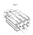
- Units of embodiments of the invention may be banked together as shown in Figure 7.
- handles 9 are of separate and individually operable clutches as described, acting on ropes 43,44,45 going to different operating areas of the boat.
Landscapes
- Engineering & Computer Science (AREA)
- General Engineering & Computer Science (AREA)
- Mechanical Engineering (AREA)
- Mechanical Operated Clutches (AREA)
- Clamps And Clips (AREA)
Claims (7)
- Seilklemme mit einem oder mehreren schwenkbaren Klemmelementen (7), wobei in einer ersten Stellung davon ein Kanal (8) gebildet wird, durch den ein Seil (40, 41, 42) hindurchgeführt werden kann, und wobei in einer zweiten Stellung davon der Kanal (8) verengt wird, sodaß das Seil durch das oder die Element(e) (7) gefaßt würde, und mit einem Lösemechanismus zum Bewirken einer Schwenkbewegung des oder der Element(e) hin zur ersten Stellung bei der Bewegung eines Betätigungshebels (9), wobei der Lösemechanismus einen Knebelmechanismus (25, 26, 27, 29) enthält, dadurch gekennzeichnet, daß der Knebelmechanismus (25, 26, 27, 29) variabel mit dem oder den Element(en) (7) durch ein Verbindungsglied (26) verbunden ist, das zwischen dem Betätigungshebel (9) und den Elementen (7) durch eine Öffnung (27) und ein Widerlager (23) einen Eingriff herstellt, wobei die Öffnung (27) eine Vielzahl an Eingriffspositionen (29) für das Widerlager (23) aufweist, sodaß eine Vielzahl an Beziehungen zwischen dem Winkel des/der Elements/e (7) in ihrer zweiten Stellung und der Position des Betätigungshebels (9), an der die Schwenkbewegung eingeleitet wird, möglich ist.
- Seilklemme nach Anspruch 1, worin die Verbreiterung des Kanals (8) durch das Schwenken des/der Elements/e (7) hin zur Ausrichtung der Achsen einer oder mehrerer schiefwinkeliger Öffnung(en) (15) in dem oder den Element(en) (7) mit der Achse des durch die Klemme geführten Seils (40, 41, 42) bewirkt wird.
- Seilklemme nach Anspruch 1 oder 2, worin eine Vielzahl an Klemmelementen (7) vorhanden ist, ein Verbindungselement (22) schwenkbar an den Elementen (7) befestigt ist, um sie zu einem Schwenken im Gleichklang zu zwingen, und das Verbindungsglied (26) variabel mit dem Verbindungselement (22) verbunden ist.
- Seilklemme nach Anspruch 3, worin das Verbindungsglied (26) eine Öffnung (27) aufweist, die mit einem Kreuzzapien (23) auf dem Verbindungselement (22) an einer beliebigen einer Vielzahl an Stellen (29) an einem Rand der Öffnung fern und in unterschiedlichen Abständen von einem Drehpunkt (25) der Verbindung auf dem Hebel (9) in Eingriff bringbar ist.
- Seilklemme nach einem der vorhergehenden Ansprüche, worin die Reibung mit dem Betätigungshebel (9) bewirkt, daß sich das Verbindungsglied (26) mit dem Hebel (9) zu bewegen trachtet.
- Seilklemme nach einem der vorhergehenden Ansprüche, worin der Betätigungshebel (9) einen händisch betriebenen Griffteil besitzt.
- Seilklemme nach einem der vorhergehenden Ansprüche, worin elastische Mittel (36) in die Elemente (7) eingreifen können, um sie zur zweiten Stellung hin zu drücken.
Applications Claiming Priority (2)
| Application Number | Priority Date | Filing Date | Title |
|---|---|---|---|
| GB919123584A GB9123584D0 (en) | 1991-11-06 | 1991-11-06 | Rope clutch |
| GB9123584 | 1991-11-06 |
Publications (2)
| Publication Number | Publication Date |
|---|---|
| EP0541348A1 EP0541348A1 (de) | 1993-05-12 |
| EP0541348B1 true EP0541348B1 (de) | 1996-03-20 |
Family
ID=10704182
Family Applications (1)
| Application Number | Title | Priority Date | Filing Date |
|---|---|---|---|
| EP92310093A Expired - Lifetime EP0541348B1 (de) | 1991-11-06 | 1992-11-04 | Seilklemme |
Country Status (6)
| Country | Link |
|---|---|
| US (1) | US5279020A (de) |
| EP (1) | EP0541348B1 (de) |
| AU (1) | AU654405B2 (de) |
| DE (1) | DE69209232T2 (de) |
| DK (1) | DK0541348T3 (de) |
| GB (1) | GB9123584D0 (de) |
Families Citing this family (10)
| Publication number | Priority date | Publication date | Assignee | Title |
|---|---|---|---|---|
| US6899203B1 (en) * | 2004-02-18 | 2005-05-31 | Thayne J. Golden | Rope management apparatus |
| US8235172B2 (en) * | 2004-06-01 | 2012-08-07 | Morgan Thompson | Combination ascender/descender |
| US20060081418A1 (en) * | 2004-06-01 | 2006-04-20 | Morgan Thompson | Ascender/descender |
| US8069803B1 (en) | 2009-08-25 | 2011-12-06 | Peter James Crawford | Boat tiller restraining device |
| DE102012010775A1 (de) * | 2012-05-31 | 2013-12-05 | Götz Siegmann | Seilklemme |
| DE102012219420B4 (de) * | 2012-10-24 | 2015-06-25 | Siemens Aktiengesellschaft | Seilbefestigungseinrichtung |
| CN113398410A (zh) * | 2014-09-16 | 2021-09-17 | 费雪派克医疗保健有限公司 | 头帽组件和具有头帽的接口组件 |
| CA2970322A1 (en) * | 2016-06-14 | 2017-12-14 | Polygroup Macau Limited (Bvi) | Control wire clamp and loop systems and methods |
| US10729210B1 (en) * | 2017-05-30 | 2020-08-04 | Apple Inc. | Watchband securement with clamp pads |
| NO345113B1 (no) * | 2018-06-25 | 2020-10-05 | Shm Solutions As | Låsemekanisme for et tau på et fartøy |
Citations (1)
| Publication number | Priority date | Publication date | Assignee | Title |
|---|---|---|---|---|
| EP0424307A2 (de) * | 1989-10-20 | 1991-04-24 | Sophus Berendsen A/S | Seilklemme |
Family Cites Families (9)
| Publication number | Priority date | Publication date | Assignee | Title |
|---|---|---|---|---|
| US1361643A (en) * | 1920-07-31 | 1920-12-07 | Norman Read | Wire and cable clamp |
| US3437981A (en) * | 1967-06-29 | 1969-04-08 | Robert Joseph Keller | Electrical wire joiner |
| FR2097028B3 (de) * | 1970-07-29 | 1976-02-20 | Ind Dev | |
| DE3160325D1 (en) * | 1980-01-29 | 1983-07-07 | Gotz Siegmann | Rope clamp |
| US4465011A (en) * | 1982-07-19 | 1984-08-14 | Schaefer Marine, Inc. | Halyard stopper |
| US4450603A (en) * | 1982-09-29 | 1984-05-29 | M. David Hirsch | Sail line stopper |
| DE3246638A1 (de) * | 1982-12-16 | 1984-06-20 | Heinz-Dieter Dr.-Ing. 1000 Berlin Adomeit | Vorrichtung zum loesbaren festklemmen eines strangfoermigen materials |
| DK153677C (da) * | 1984-09-26 | 1988-12-27 | Berendsen Sophus Marine As | Laasemekanisme til fastlaasning af et tov, en line eller et lignende langstrakt, boejeligt traekorgan |
| DE3601233A1 (de) * | 1985-01-18 | 1986-07-24 | Pfeiffer Gerätebau GmbH, 7760 Radolfzell | Klemm-beschlag fuer tauwerk |
-
1991
- 1991-11-06 GB GB919123584A patent/GB9123584D0/en active Pending
-
1992
- 1992-11-04 DK DK92310093.7T patent/DK0541348T3/da active
- 1992-11-04 EP EP92310093A patent/EP0541348B1/de not_active Expired - Lifetime
- 1992-11-04 DE DE69209232T patent/DE69209232T2/de not_active Expired - Lifetime
- 1992-11-05 US US07/972,291 patent/US5279020A/en not_active Expired - Lifetime
- 1992-11-05 AU AU28168/92A patent/AU654405B2/en not_active Expired
Patent Citations (1)
| Publication number | Priority date | Publication date | Assignee | Title |
|---|---|---|---|---|
| EP0424307A2 (de) * | 1989-10-20 | 1991-04-24 | Sophus Berendsen A/S | Seilklemme |
Also Published As
| Publication number | Publication date |
|---|---|
| AU654405B2 (en) | 1994-11-03 |
| DK0541348T3 (da) | 1996-06-10 |
| DE69209232T2 (de) | 1996-09-19 |
| AU2816892A (en) | 1993-05-13 |
| DE69209232D1 (de) | 1996-04-25 |
| GB9123584D0 (en) | 1992-01-02 |
| US5279020A (en) | 1994-01-18 |
| EP0541348A1 (de) | 1993-05-12 |
Similar Documents
| Publication | Publication Date | Title |
|---|---|---|
| EP0541348B1 (de) | Seilklemme | |
| EP0424307B1 (de) | Seilklemme | |
| US4217847A (en) | Self-release cam cleat | |
| US3765061A (en) | Lever-release cam cleat | |
| US6360408B1 (en) | Hooked latch with ball lock sliding sleeve retainer | |
| EP0179302B1 (de) | Klemmvorrichtung für Seile | |
| US7673917B2 (en) | Variable diameter lifting tongs | |
| JPH01216139A (ja) | ロープ把持装置 | |
| US20030071253A1 (en) | Lifting device | |
| US5797639A (en) | Lock box | |
| US11118655B2 (en) | Assembling structure for timely and securely locking and releasing a rope | |
| US4113298A (en) | Lifting clamp and spring therefor | |
| US6601829B2 (en) | Pulley system with gripping block and tackle for load handling | |
| US20070063522A1 (en) | Lifting assembly | |
| US5429463A (en) | Load binder having removable handle | |
| US3297354A (en) | Lifting clamp | |
| US3395892A (en) | Over-center load binder and gripping device | |
| US5755476A (en) | Hoist lock | |
| EP0079593B1 (de) | Flaschenzug | |
| US4569548A (en) | Remotely releasable choker | |
| EP1082197B1 (de) | Werkzeug zum spannen von drähten | |
| CA2858230C (en) | Bundle grapple | |
| US4455720A (en) | Clamp apparatus | |
| US20040187271A1 (en) | Sliding buckle for a rescue sling | |
| US10787347B1 (en) | Self-locking pulley |
Legal Events
| Date | Code | Title | Description |
|---|---|---|---|
| PUAI | Public reference made under article 153(3) epc to a published international application that has entered the european phase |
Free format text: ORIGINAL CODE: 0009012 |
|
| AK | Designated contracting states |
Kind code of ref document: A1 Designated state(s): DE DK FR GB IT NL SE |
|
| 17P | Request for examination filed |
Effective date: 19930924 |
|
| 17Q | First examination report despatched |
Effective date: 19941102 |
|
| GRAA | (expected) grant |
Free format text: ORIGINAL CODE: 0009210 |
|
| AK | Designated contracting states |
Kind code of ref document: B1 Designated state(s): DE DK FR GB IT NL SE |
|
| REF | Corresponds to: |
Ref document number: 69209232 Country of ref document: DE Date of ref document: 19960425 |
|
| ITF | It: translation for a ep patent filed | ||
| REG | Reference to a national code |
Ref country code: DK Ref legal event code: T3 |
|
| ET | Fr: translation filed | ||
| PLBE | No opposition filed within time limit |
Free format text: ORIGINAL CODE: 0009261 |
|
| 26N | No opposition filed | ||
| REG | Reference to a national code |
Ref country code: GB Ref legal event code: IF02 |
|
| PGFP | Annual fee paid to national office [announced via postgrant information from national office to epo] |
Ref country code: DE Payment date: 20101026 Year of fee payment: 19 |
|
| PGFP | Annual fee paid to national office [announced via postgrant information from national office to epo] |
Ref country code: IT Payment date: 20101027 Year of fee payment: 19 Ref country code: GB Payment date: 20101020 Year of fee payment: 19 |
|
| PGFP | Annual fee paid to national office [announced via postgrant information from national office to epo] |
Ref country code: SE Payment date: 20111026 Year of fee payment: 20 Ref country code: NL Payment date: 20111031 Year of fee payment: 20 Ref country code: DK Payment date: 20111026 Year of fee payment: 20 Ref country code: FR Payment date: 20111103 Year of fee payment: 20 |
|
| REG | Reference to a national code |
Ref country code: DE Ref legal event code: R071 Ref document number: 69209232 Country of ref document: DE |
|
| REG | Reference to a national code |
Ref country code: DK Ref legal event code: EUP |
|
| REG | Reference to a national code |
Ref country code: DE Ref legal event code: R071 Ref document number: 69209232 Country of ref document: DE |
|
| REG | Reference to a national code |
Ref country code: NL Ref legal event code: V4 Effective date: 20121104 |
|
| REG | Reference to a national code |
Ref country code: GB Ref legal event code: PE20 Expiry date: 20121103 |
|
| REG | Reference to a national code |
Ref country code: SE Ref legal event code: EUG |
|
| PG25 | Lapsed in a contracting state [announced via postgrant information from national office to epo] |
Ref country code: GB Free format text: LAPSE BECAUSE OF EXPIRATION OF PROTECTION Effective date: 20121103 |