EP0541392B1 - Metallnachweis - Google Patents
Metallnachweis Download PDFInfo
- Publication number
- EP0541392B1 EP0541392B1 EP92310192A EP92310192A EP0541392B1 EP 0541392 B1 EP0541392 B1 EP 0541392B1 EP 92310192 A EP92310192 A EP 92310192A EP 92310192 A EP92310192 A EP 92310192A EP 0541392 B1 EP0541392 B1 EP 0541392B1
- Authority
- EP
- European Patent Office
- Prior art keywords
- predetermined point
- circuit
- processing line
- metal
- electric circuit
- Prior art date
- Legal status (The legal status is an assumption and is not a legal conclusion. Google has not performed a legal analysis and makes no representation as to the accuracy of the status listed.)
- Expired - Lifetime
Links
Images


Classifications
-
- G—PHYSICS
- G01—MEASURING; TESTING
- G01V—GEOPHYSICS; GRAVITATIONAL MEASUREMENTS; DETECTING MASSES OR OBJECTS; TAGS
- G01V3/00—Electric or magnetic prospecting or detecting; Measuring magnetic field characteristics of the earth, e.g. declination, deviation
- G01V3/08—Electric or magnetic prospecting or detecting; Measuring magnetic field characteristics of the earth, e.g. declination, deviation operating with magnetic or electric fields produced or modified by objects or geological structures or by detecting devices
- G01V3/10—Electric or magnetic prospecting or detecting; Measuring magnetic field characteristics of the earth, e.g. declination, deviation operating with magnetic or electric fields produced or modified by objects or geological structures or by detecting devices using induction coils
- G01V3/101—Electric or magnetic prospecting or detecting; Measuring magnetic field characteristics of the earth, e.g. declination, deviation operating with magnetic or electric fields produced or modified by objects or geological structures or by detecting devices using induction coils by measuring the impedance of the search coil; by measuring features of a resonant circuit comprising the search coil
-
- B—PERFORMING OPERATIONS; TRANSPORTING
- B21—MECHANICAL METAL-WORKING WITHOUT ESSENTIALLY REMOVING MATERIAL; PUNCHING METAL
- B21B—ROLLING OF METAL
- B21B38/00—Methods or devices for measuring, detecting or monitoring specially adapted for metal-rolling mills, e.g. position detection, inspection of the product
-
- B—PERFORMING OPERATIONS; TRANSPORTING
- B21—MECHANICAL METAL-WORKING WITHOUT ESSENTIALLY REMOVING MATERIAL; PUNCHING METAL
- B21C—MANUFACTURE OF METAL SHEETS, WIRE, RODS, TUBES, PROFILES OR LIKE SEMI-MANUFACTURED PRODUCTS OTHERWISE THAN BY ROLLING; AUXILIARY OPERATIONS USED IN CONNECTION WITH METAL-WORKING WITHOUT ESSENTIALLY REMOVING MATERIAL
- B21C51/00—Measuring, gauging, indicating, counting, or marking devices specially adapted for use in the production or manipulation of material in accordance with subclasses B21B - B21F
-
- B—PERFORMING OPERATIONS; TRANSPORTING
- B21—MECHANICAL METAL-WORKING WITHOUT ESSENTIALLY REMOVING MATERIAL; PUNCHING METAL
- B21B—ROLLING OF METAL
- B21B2273/00—Path parameters
- B21B2273/18—Presence of product
Definitions
- This invention relates to the detection of moving metal objects, and especially to the tracking of hot metal slabs in processing lines.
- processing line for hot metal is that for the production of hot rolled narrow strip.
- the metal in the form of a slab is heated, rolled hot to controlled dimensions and coiled.
- Such lines work with a variety of steel grades, and even non-ferrous metals, and are computer controlled so that the dimensions of the processed strip can vary from strip to strip as they pass down the line.
- These processing lines can produce a variety of different qualities and sizes of output in a continuous mix of jobs flowing down the line.
- the metal feed stock in the form of slabs must be offered to the line in the correct sequence of material grades, and is heated in a reheat furnace for about an hour before being processed on the line. In many installations it is common to have more than one furnace so that the line handles the output from two or more furnaces.
- Such furnaces are often of the pusher type in which slabs are loaded in at a cold end and are pushed through the furnace as more slabs are loaded. At the output end having passed through the furnace by being pushed by the following slabs they drop onto the processing line to be processed.
- the apparatus is disposed adjacent metal objects passing on a belt, and includes two inductively related coils and a third or balance coil, the three coils being arranged to produce a null balance of the inductive effect between the two inductively related coils.
- apparatus for detecting the presence of metal items passing a predetermined point in a processing line for those items including at least a part of an inductive electric circuit disposed adjacent the predetermined point in the processing line, and means for detecting changes of inductance of the electric circuit due to the metal items passing the predetermined point, and wherein the inductive electric circuit comprises a tuned circuit and means are included for measuring the change in the resonant frequency of the tuned circuit including the coil, characterised in that the inductive electric circuit includes means for automatic resonance re-tuning to compensate for drift in the resonant frequency thereof.
- a method of detecting the presence of metal items passing a predetermined point in a processing line for those items comprising disposing at least part of an inductive electric circuit adjacent the predetermined point in the processing line and detecting changes of inductance of the electric circuit due to the metal items passing the predetermined point, wherein the inductive electric circuit comprises a tuned circuit and including measuring the change in the resonant frequency of the tuned circuit including the coil, characterised by automatically re-tuning the circuit to compensate for drift in the resonant frequency thereof.
- the electric inductive circuit may include a coil or loop located close to the predetermined point in the processing line.
- the arrangement preferably is such that the period for re-tuning the detectors may be less than 10 seconds.
- a detector connected to receive output signals from the plurality of circuits and arranged to transmit an ongoing positive signal indicative of the passage of a metal item past a predetermined point on the basis of the receipt of a predetermined number of inductance change signals from the plurality of circuits.
- the processing line may comprise a hot rolling mill and the metal items may comprise hot metal slabs, in which case at least part of at least one inductive electric circuit may be situated adjacent the exit zone from at least one reheat furnace of the rolling mill prior to a conveyor to a rolling line.
- the one or more coil or loops may be provided adjacent to the drop out zone from the or each reheat furnace.
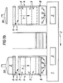
- the rolling mill has a processing line 1 and slabs progress in the direction 2 so as to be rolled into strip.
- the metal slabs 3 are heated in reheat furnaces 4 fired by gas or some other fuel of known kind. Two such furnaces are provided and for convenience the full length of the furnaces has not been shown as indicated by the breaks 5.
- the process of feeding the metal slabs to the processing line is that at the cold end of the furnace 6 a cold slab is pushed by a pusher 30 in the direction arrow 7 in the order in which it will be required to be dropped out of the furnace onto the processing line.
- the process of pushing the cold slab into the furnace transmits the push through the slabs being heated in the furnace until the one at the exit 8 to the furnace drops over the slope and falls onto the processing line.
- the length of time it takes a slab to pass through the furnace from cold input to dropping out onto the processing line can be an hour or more.
- the sequence in which the slabs are fed into the furnace is recorded on a process computer 32 which tracks the progress of the slabs through the furnace and as a new slab is required from the appropriate furnace so as to eject the hot slab required onto the processing line.
- the coils of one furnace are shown at 20a, 20b, 20c and 20d and as will be seen, four coils are shown.
- the coils 20a, 20b, 20c are initially functional, and coil 20d is a spare.
- the coils may for example each be of 6 turns of copper wire of 2.5mm2 thick and insulated up to 250°C working temperature. They may be rectangular in plan of the order of 300mm by 450mm. Electrically the coil may have a resistance of 1.2 ohms, and an inductance of 48 microhenries.
- Elements of the operating circuitry 31 are shown for coil 20a only; the elements for coils 20b and 20c are identical.
- the coil 20a is included in a tuned circuit with a variable capacitance 21 and manually adjustable ballast resistance 22 and ballast inductance 23.
- the inductance and resistance are included to enable manual adjustment of the operating characteristics of the circuit to be made.
- the resonant frequency of the tuned frequency circuit may be measured by one of a number of techniques already known per se . With the arrangement illustrated it is measured by means of a detector 24, the method comprising injecting into the tuned circuit a sweep frequency and measuring the response of the circuit. The frequency at which the circuit oscillates is fed to a comparator 25 which compares the measured resonant frequency of the circuit with a preset frequency of, say, 400Hz. If the measured frequency deviates from 400 Hz by more than a preset amount then a positive output is provided from the comparator 25.
- This output is fed into detector 26 (along with similar outputs from the corresponding circuitry of coils 20b and 20c), which provides an output 27 to the process computer 30 when two out of three of the comparators are providing a positive signal.
- detector 26 (along with similar outputs from the corresponding circuitry of coils 20b and 20c), which provides an output 27 to the process computer 30 when two out of three of the comparators are providing a positive signal.
- the comparator 25 also feeds a timer 28.
- a timer 28 In operation it has been found that because of changes in the external circumstances the resonant frequency of the circuits can change and drift. The reasons why drift may occur are well known, and include thermal changes, which would be expected. In addition, it is possible for scale and other debris to build up on the furnace floor and this will effect the resonant frequency. For this reason a feedback circuit from the frequency detector 24 and comparator 25 is provided through the timer 28 to the variable capacitor 21. This is arranged so that should the output from the comparator 25 of a particular measuring circuit be positive for more than five seconds, the timer begins to vary the variable capacitor while observing the change of frequency produced in the output from the frequency detector. By then adjusting the value of the capacitance so that the frequency is re-tuned to 400Hz the circuit is restored to its central operating condition, and the affects of scale build up and drift of calibration for example are eliminated.
- Another distinct advantage of the inductance detection of the hot metal is that it does not rely on the magnetic properties of the metal. This is an advantage, because hot strip lines are sometimes used for rolling non-ferrous metals; for example copper may be rolled.
- the system described will work with copper slabs as well, although it may be necessary to ensure that the inductive change by a copper slab is within the limits set for the control circuitry to activate.
Landscapes
- Engineering & Computer Science (AREA)
- Physics & Mathematics (AREA)
- Mechanical Engineering (AREA)
- Remote Sensing (AREA)
- Life Sciences & Earth Sciences (AREA)
- General Physics & Mathematics (AREA)
- Geology (AREA)
- General Life Sciences & Earth Sciences (AREA)
- Environmental & Geological Engineering (AREA)
- Geophysics (AREA)
- Electromagnetism (AREA)
- Analysing Materials By The Use Of Radiation (AREA)
- Superconductors And Manufacturing Methods Therefor (AREA)
- Other Investigation Or Analysis Of Materials By Electrical Means (AREA)
- Secondary Cells (AREA)
- Glass Compositions (AREA)
- Geophysics And Detection Of Objects (AREA)
- Investigating Or Analyzing Materials By The Use Of Magnetic Means (AREA)
- Metal Rolling (AREA)
Claims (6)
- Vorrichtung zum Erkennen des Vorhandenseins (der Gegenwart) von Metallobjekten (3), die einen vorgegebenen Punkt (8) in einer Verarbeitungslinie (1) solcher Objekte (3) passieren, wobei die Vorrichtung mindestens einen Teil eines induktiven elektrischen Schaltkreises (31) umfaßt, der dem vorgegebenen Punkt (8) in der Verarbeitungslinie (1) benachbart angeordnet ist, und die Mittel (24, 25) zum Erkennen von Änderungen der Induktivität des elektrischen Schaltkreises (31) infolge der Metallobjekte (3), die den vorgegebenen Punkt (8) passieren, umfaßt und wobei der elektrische Schaltkreis (31) einen abgetimmten Schaltkreis enthält und die Mittel (24, 25) zur Messung der Änderung der Resonanzfrequenz des abgetimmten Schaltkreises, die die Wicklung umfaßt, eingeschlossen sind, dadurch gekennzeichnet, daß der induktive elektrische Schaltkreis (31) Mittel (21, 24, 25, 28) zu einer automatischen Resonanz-Wiederabstimmung zur Kompensation der Verschiebung seiner Resonanzfrequenz enthält.
- Vorrichtung nach Anspruch 1, dadurch gekennzeichnet, daß der elektrische induktive Schaltkreis (31) eine Wicklung (9, 20a, 20b, 20c) umfaßt, die nahe dem vorgegebenen Punkt (8) in der Verarbeitungslinie (1) angeordnet ist.
- Vorrichtung nach einem der vorstehenden Ansprüche, dadurch gekennzeichnet, daß dort eine Vielzahl von induktiven elektrischen Schaltkreisen (31) benachbart zu dem vorgegebenen Punkt (8) vorgesehen sind und ein Detektor (26) zum Empfang von Ausgangssignalen von der Vielzahl der Schaltkreise an diese angeschlossen ist und ausgebildet ist, um ein andauerndes positives Signal auszusenden, das aufgrund des Empfangs einer vorgegebenen Anzahl von Induktivitätsänderunges-Signalen von der Vielzahl der Schaltkreise (31) den Durchlauf von einem Metallobjekt an dem vorgegebenen Punkt (8) anzeigt.
- Vorrichtung nach eindem der vorstehenden Ansprüche, wobei die Verarbeitungslinie eine Warmwalze umfaßt und die Metallobjekte heiße Metalltafeln sind, dadurch gekennzeichnet, daß mindestens ein Teil von mindestens einem induktiven elekrischen Schaltkreis (31) zur Ausgangszone mindestens eines Wiederaufheizofens (4) vor einem Förderer (1) zu einer Walzlinie angeordnet ist.
- Verfahren zum Erkennen von Metallobjekten, die einen vorgegebenen Punkt in einer Verarbeitungslinie für solche Objekte passieren, wobei mindestens ein Teil eines induktiven elektrischen Schaltkreises benachbart zum vorgegebenen Punkt in der Verarbeitungslinie angeordnet wird, und Änderungen der Induktivität des elektrischen Schaltkreises infolge des Passierens der Metallobjekte am vorgegebenen Punkt erkannt werden, wobei der induktive elektrische Schaltkreis einen abgestimmten Schaltkreis enthält und ein Messen der Änderung der Resonanzfrequenz des abgestimmten Schaltkreises einschließlich der Wicklung umfaßt, dadurch gekennzeichnet, daß automatisch eine Wiederabstimmung des Schaltkreises erfolgt, um die Verschiebung der Resonanzfrequenz darin zu kompensieren.
- Verfahren nach Anspruch 5, wobei eine Vielzahl induktiver elektrischer Schaltkreise benachbart zu dem vorgegebenen Punkt vorgesehen ist, dadurch gekennzeichnet, daß Ausgangssignale von der Vielzahl von Schaltkreisen erkannt werden und ein andauerndes positives Signal übertragen wird, das aufgrund des Empfangs von einer vorgegebenen Anzahl von Induktivitätsänderungssignalen von der Vielzahl der Schaltkreise anzeigt, daß ein Metallobjekt den vorgegebenen Punkt passiert.
Applications Claiming Priority (2)
| Application Number | Priority Date | Filing Date | Title |
|---|---|---|---|
| GB919123664A GB9123664D0 (en) | 1991-11-07 | 1991-11-07 | Metal detection |
| GB9123664 | 1991-11-07 |
Publications (2)
| Publication Number | Publication Date |
|---|---|
| EP0541392A1 EP0541392A1 (de) | 1993-05-12 |
| EP0541392B1 true EP0541392B1 (de) | 1996-02-28 |
Family
ID=10704236
Family Applications (1)
| Application Number | Title | Priority Date | Filing Date |
|---|---|---|---|
| EP92310192A Expired - Lifetime EP0541392B1 (de) | 1991-11-07 | 1992-11-06 | Metallnachweis |
Country Status (4)
| Country | Link |
|---|---|
| EP (1) | EP0541392B1 (de) |
| AT (1) | ATE134538T1 (de) |
| DE (1) | DE69208590T2 (de) |
| GB (1) | GB9123664D0 (de) |
Cited By (1)
| Publication number | Priority date | Publication date | Assignee | Title |
|---|---|---|---|---|
| US9410823B2 (en) | 2012-07-13 | 2016-08-09 | Qualcomm Incorporated | Systems, methods, and apparatus for detection of metal objects in a predetermined space |
Family Cites Families (4)
| Publication number | Priority date | Publication date | Assignee | Title |
|---|---|---|---|---|
| US2554575A (en) * | 1944-03-07 | 1951-05-29 | Anaconda Copper Mining Co | Magnetic detector |
| US2547407A (en) * | 1948-06-18 | 1951-04-03 | Peyton J Nelson | Apparatus for detecting metal objects on a moving belt |
| US3872964A (en) * | 1972-05-19 | 1975-03-25 | Scandia Packaging Mach | Assembly for detecting irregular feed conditions |
| US4567410A (en) * | 1984-12-03 | 1986-01-28 | Continental Can Company, Inc. | Capacitive article density monitor |
-
1991
- 1991-11-07 GB GB919123664A patent/GB9123664D0/en active Pending
-
1992
- 1992-11-06 DE DE69208590T patent/DE69208590T2/de not_active Expired - Fee Related
- 1992-11-06 AT AT92310192T patent/ATE134538T1/de not_active IP Right Cessation
- 1992-11-06 EP EP92310192A patent/EP0541392B1/de not_active Expired - Lifetime
Cited By (4)
| Publication number | Priority date | Publication date | Assignee | Title |
|---|---|---|---|---|
| US9410823B2 (en) | 2012-07-13 | 2016-08-09 | Qualcomm Incorporated | Systems, methods, and apparatus for detection of metal objects in a predetermined space |
| US9726518B2 (en) | 2012-07-13 | 2017-08-08 | Qualcomm Incorporated | Systems, methods, and apparatus for detection of metal objects in a predetermined space |
| US10627257B2 (en) | 2012-07-13 | 2020-04-21 | Witricity Corporation | Systems, methods, and apparatus for detection of metal objects in a predetermined space |
| US11077762B2 (en) | 2012-07-13 | 2021-08-03 | Witricity Corporation | Systems, methods, and apparatus for detection of metal objects in a predetermined space |
Also Published As
| Publication number | Publication date |
|---|---|
| GB9123664D0 (en) | 1992-01-02 |
| EP0541392A1 (de) | 1993-05-12 |
| DE69208590T2 (de) | 1996-10-24 |
| ATE134538T1 (de) | 1996-03-15 |
| DE69208590D1 (de) | 1996-04-04 |
Similar Documents
| Publication | Publication Date | Title |
|---|---|---|
| CA2806993C (en) | Method and control and tracking system of the charge of material transported by a continuous supply conveyor of a metallurgical furnace, particularly an electric furnace for the production of steel | |
| EP0541392B1 (de) | Metallnachweis | |
| CN101522322A (zh) | 分选细小有色金属和绝缘导线物件的方法和设备 | |
| CN105473971A (zh) | 用于控制和/或调节加工金属材料的生产线的退火炉或热处理炉的设备和方法 | |
| DE3439369A1 (de) | Verfahren und vorrichtung zum detektieren von schlacke | |
| EP1319163B1 (de) | Verfahren zur messung der oberflächenhöhe eines materialbetts, das auf einem förderband einer thermischen behandlung zugeführt wird | |
| EP1134564A2 (de) | Kombinatorischer Wäge- und Zählapparat | |
| US4142237A (en) | Process for tracking a welded joint in a continuous long material in a production line | |
| KR20180074319A (ko) | 무선 센서 노드, 이를 이용한 연원료 트래킹 장치 및 이를 이용한 고로 노내 측정 장치 | |
| CA2054423C (en) | Adaptive control for reheat furnace | |
| JP5744432B2 (ja) | 高周波焼入れシステム及び高周波焼入れ異常判定方法 | |
| US3619604A (en) | Digital distance to coupling detection | |
| KR100939893B1 (ko) | 열연강판의 냉각제어 방법 | |
| KR101003271B1 (ko) | 가열로 소재 추적 방법 | |
| JP3662300B2 (ja) | 焼成炉用冷却装置 | |
| WO2000078474A1 (en) | Hot rolling method and equipment | |
| JPS6145819A (ja) | コンベヤ−による輸送系の異常検出方法 | |
| JP5453955B2 (ja) | 熱延用スラブの幅圧下方法 | |
| US3485985A (en) | Apparatus for induction heating of slabs | |
| EP1065529B1 (de) | Verfahren und Vorrichtung zur Detektion von Fremdkörpern | |
| JPS59134588A (ja) | 金属片側端部の誘導加熱方法 | |
| US20250283708A1 (en) | Induction annealing apparatus | |
| US3193271A (en) | Blast controlling device for blast furnaces | |
| KR100851223B1 (ko) | 석탄 및 미분탄 중량 제어장치 | |
| JPH0375307A (ja) | データトラッキング制御方法 |
Legal Events
| Date | Code | Title | Description |
|---|---|---|---|
| PUAI | Public reference made under article 153(3) epc to a published international application that has entered the european phase |
Free format text: ORIGINAL CODE: 0009012 |
|
| AK | Designated contracting states |
Kind code of ref document: A1 Designated state(s): AT BE CH DE DK ES FR GB GR IE IT LI LU MC NL PT SE |
|
| 17P | Request for examination filed |
Effective date: 19931026 |
|
| 17Q | First examination report despatched |
Effective date: 19950203 |
|
| GRAA | (expected) grant |
Free format text: ORIGINAL CODE: 0009210 |
|
| AK | Designated contracting states |
Kind code of ref document: B1 Designated state(s): AT BE CH DE DK ES FR GB GR IE IT LI LU MC NL PT SE |
|
| PG25 | Lapsed in a contracting state [announced via postgrant information from national office to epo] |
Ref country code: LI Effective date: 19960228 Ref country code: GR Free format text: LAPSE BECAUSE OF FAILURE TO SUBMIT A TRANSLATION OF THE DESCRIPTION OR TO PAY THE FEE WITHIN THE PRESCRIBED TIME-LIMIT Effective date: 19960228 Ref country code: FR Effective date: 19960228 Ref country code: ES Free format text: THE PATENT HAS BEEN ANNULLED BY A DECISION OF A NATIONAL AUTHORITY Effective date: 19960228 Ref country code: DK Effective date: 19960228 Ref country code: CH Effective date: 19960228 Ref country code: AT Effective date: 19960228 |
|
| REF | Corresponds to: |
Ref document number: 134538 Country of ref document: AT Date of ref document: 19960315 Kind code of ref document: T |
|
| REG | Reference to a national code |
Ref country code: IE Ref legal event code: FG4D Free format text: 67390 |
|
| REF | Corresponds to: |
Ref document number: 69208590 Country of ref document: DE Date of ref document: 19960404 |
|
| ITF | It: translation for a ep patent filed | ||
| PG25 | Lapsed in a contracting state [announced via postgrant information from national office to epo] |
Ref country code: PT Effective date: 19960528 |
|
| PG25 | Lapsed in a contracting state [announced via postgrant information from national office to epo] |
Ref country code: SE Effective date: 19960531 |
|
| EN | Fr: translation not filed | ||
| REG | Reference to a national code |
Ref country code: CH Ref legal event code: PL |
|
| PG25 | Lapsed in a contracting state [announced via postgrant information from national office to epo] |
Ref country code: IE Free format text: LAPSE BECAUSE OF NON-PAYMENT OF DUE FEES Effective date: 19961106 |
|
| PG25 | Lapsed in a contracting state [announced via postgrant information from national office to epo] |
Ref country code: LU Free format text: LAPSE BECAUSE OF NON-PAYMENT OF DUE FEES Effective date: 19961130 |
|
| PLBE | No opposition filed within time limit |
Free format text: ORIGINAL CODE: 0009261 |
|
| 26N | No opposition filed | ||
| PG25 | Lapsed in a contracting state [announced via postgrant information from national office to epo] |
Ref country code: MC Effective date: 19970531 |
|
| PGFP | Annual fee paid to national office [announced via postgrant information from national office to epo] |
Ref country code: NL Payment date: 20010927 Year of fee payment: 10 |
|
| PGFP | Annual fee paid to national office [announced via postgrant information from national office to epo] |
Ref country code: GB Payment date: 20011019 Year of fee payment: 10 |
|
| PGFP | Annual fee paid to national office [announced via postgrant information from national office to epo] |
Ref country code: DE Payment date: 20011029 Year of fee payment: 10 |
|
| PGFP | Annual fee paid to national office [announced via postgrant information from national office to epo] |
Ref country code: BE Payment date: 20011115 Year of fee payment: 10 |
|
| REG | Reference to a national code |
Ref country code: GB Ref legal event code: IF02 |
|
| PG25 | Lapsed in a contracting state [announced via postgrant information from national office to epo] |
Ref country code: GB Free format text: LAPSE BECAUSE OF NON-PAYMENT OF DUE FEES Effective date: 20021106 |
|
| PG25 | Lapsed in a contracting state [announced via postgrant information from national office to epo] |
Ref country code: BE Free format text: LAPSE BECAUSE OF NON-PAYMENT OF DUE FEES Effective date: 20021130 |
|
| BERE | Be: lapsed |
Owner name: BRITISH *STEEL P.L.C. Effective date: 20021130 |
|
| PG25 | Lapsed in a contracting state [announced via postgrant information from national office to epo] |
Ref country code: NL Free format text: LAPSE BECAUSE OF NON-PAYMENT OF DUE FEES Effective date: 20030601 |
|
| PG25 | Lapsed in a contracting state [announced via postgrant information from national office to epo] |
Ref country code: DE Free format text: LAPSE BECAUSE OF NON-PAYMENT OF DUE FEES Effective date: 20030603 |
|
| GBPC | Gb: european patent ceased through non-payment of renewal fee | ||
| NLV4 | Nl: lapsed or anulled due to non-payment of the annual fee |
Effective date: 20030601 |
|
| PG25 | Lapsed in a contracting state [announced via postgrant information from national office to epo] |
Ref country code: IT Free format text: LAPSE BECAUSE OF NON-PAYMENT OF DUE FEES;WARNING: LAPSES OF ITALIAN PATENTS WITH EFFECTIVE DATE BEFORE 2007 MAY HAVE OCCURRED AT ANY TIME BEFORE 2007. THE CORRECT EFFECTIVE DATE MAY BE DIFFERENT FROM THE ONE RECORDED. Effective date: 20051106 |