EP0541460A2 - Imprimante laser à faisceaux multiples - Google Patents
Imprimante laser à faisceaux multiples Download PDFInfo
- Publication number
- EP0541460A2 EP0541460A2 EP92420389A EP92420389A EP0541460A2 EP 0541460 A2 EP0541460 A2 EP 0541460A2 EP 92420389 A EP92420389 A EP 92420389A EP 92420389 A EP92420389 A EP 92420389A EP 0541460 A2 EP0541460 A2 EP 0541460A2
- Authority
- EP
- European Patent Office
- Prior art keywords
- printer
- optical fibers
- lasers
- beams
- output
- Prior art date
- Legal status (The legal status is an assumption and is not a legal conclusion. Google has not performed a legal analysis and makes no representation as to the accuracy of the status listed.)
- Withdrawn
Links
Images


Classifications
-
- B—PERFORMING OPERATIONS; TRANSPORTING
- B41—PRINTING; LINING MACHINES; TYPEWRITERS; STAMPS
- B41J—TYPEWRITERS; SELECTIVE PRINTING MECHANISMS, i.e. MECHANISMS PRINTING OTHERWISE THAN FROM A FORME; CORRECTION OF TYPOGRAPHICAL ERRORS
- B41J2/00—Typewriters or selective printing mechanisms characterised by the printing or marking process for which they are designed
- B41J2/435—Typewriters or selective printing mechanisms characterised by the printing or marking process for which they are designed characterised by selective application of radiation to a printing material or impression-transfer material
- B41J2/447—Typewriters or selective printing mechanisms characterised by the printing or marking process for which they are designed characterised by selective application of radiation to a printing material or impression-transfer material using arrays of radiation sources
- B41J2/46—Typewriters or selective printing mechanisms characterised by the printing or marking process for which they are designed characterised by selective application of radiation to a printing material or impression-transfer material using arrays of radiation sources characterised by using glass fibres
-
- B—PERFORMING OPERATIONS; TRANSPORTING
- B41—PRINTING; LINING MACHINES; TYPEWRITERS; STAMPS
- B41J—TYPEWRITERS; SELECTIVE PRINTING MECHANISMS, i.e. MECHANISMS PRINTING OTHERWISE THAN FROM A FORME; CORRECTION OF TYPOGRAPHICAL ERRORS
- B41J2/00—Typewriters or selective printing mechanisms characterised by the printing or marking process for which they are designed
- B41J2/435—Typewriters or selective printing mechanisms characterised by the printing or marking process for which they are designed characterised by selective application of radiation to a printing material or impression-transfer material
- B41J2/475—Typewriters or selective printing mechanisms characterised by the printing or marking process for which they are designed characterised by selective application of radiation to a printing material or impression-transfer material for heating selectively by radiation or ultrasonic waves
Definitions
- the invention relates to printers and, in particular, to printers in which images are generated on a line-by-line basis.
- Various printers use modulated laser beams to produce images on receivers or printing media.
- a dye-donor sheet is interposed between a laser source of energy and a receiver.
- a modulated laser beam is scanned across the dye-donor sheet and causes a transfer of dye from the dye-donor sheet to selected portions of the receiver to produce an image thereon.
- An example of such a printer is described in U.S. Patent Application Serial No. 457,593 (S. Sarraf, filed December 27, 1990) entitled "Thermal Printer", which is assigned to the assignee of the present patent application.
- Prior art printers typically employ a single laser to perform image generation. This usually requires that such a printer produce images with a series of single-line scans. When these single laser printers are used to produce high resolution images (e.g., 2000 dots per inch and greater) their speed of operation is quite slow. The production of a single image can take as long as several minutes.
- laser printers which act as thermal printers require application of substantial amounts of concentrated energy at small and well defined spots on a dye-donor sheet. This requires the use of relatively high power lasers and complex optical systems to focus output beams of the lasers at desired points.
- the present invention is directed to a thermal printer in which a plurality of lasers are used to generate an image on a receiver in a multi-line mode of operation.
- Each of the lasers has its output light directed through a separate optical fiber.
- Output ends of the optical fibers are closely and accurately spaced in a grooved array support. All output beams from the optical fibers are simultaneously scanned across a receiver as each of the beams is individually modulated in accordance with image formation data.
- An image is formed with a plurality of image lines being generated substantially simultaneously.
- the present invention is directed to a printer for progressively producing an image on a receiver on a line-by-line basis with modulated laser beams.
- the printer comprises a plurality of independently operable lasers, and a plurality of optical fibers, having input and output ends. Each input end of an optical fiber is optically coupled to one of the lasers. Each output end of the optical fibers is positioned in an array in which the optical fibers are spaced a predetermined distance from each other. Means are provided for deflecting output beams from all of the optical fibers simultaneously to scan the output beams across a surface of the receiver whereby a plurality of lines of an image are produced simultaneously.
- the invention is directed to a printer for progressively producing an image on a receiver on a multiple line basis with modulated laser beams.
- the printer comprises a plurality of independently operable lasere.
- the lasers are spaced from each other such that the lasers are thermally independent of each other.
- An optical fiber having input and output ends is optically coupled to each of the , lasers at the input end of the optical fiber.
- Each output end of the optical fibers is positioned in an array in which the optical fibers are spaced a predetermined distance from each other.
- Means are provided for deflecting output beams from all of the optical fibers simultaneously to scan the output beams across a surface of the receiver whereby a plurality of lines of an image are produced simultaneously.
- the printer 20 comprises a diode laser 22, a first collimating lens 24, a cylindrical lens 26, a second collimating lens 28, a stationary mirror 30, a beam-deflecting galvanometer 32, an F-Theta lens 34 and a translating stage 36.
- the printer 20 produces an image on a receiver 38 which is supported on the translating stage 36.
- the receiver 38 is a transparency or slide in 35 mm format.
- the printer 20 produces a desired image on the receiver 38 by transferring dote of dye onto the receiver from an overlying dye-donor sheet (not shown for purposes of clarity).
- a transfer of a dot of dye to the receiver 38 occurs when a concentrated beam 40 of laser light heats a localized portion of the dye-donor sheet. This localized heating causes a sublimation of a dot of dye on the sheet and a transfer of the dye onto the receiver 38 in the manner described in the above-mentioned U.S. Patent Application Serial No. 457,593, which is incorporated herein by reference.
- the beam 40 is produced by the laser 22.
- An output light level of the laser 22 is modulated in accordance with image data that is fed to the printer 20 from an image source (not shown) in a well-known manner.
- a complex combination of optical and scanning devices is needed to transfer modulated light from the laser 22 to a desired localized spot on the receiver 38.
- the first collimating lens 24 collimates a diverging output beam 42 from the laser diode 22.
- An emerging beam 44 from the collimating lens 24 has an elliptical cross section.
- a beam with an elliptical cross section is not suitable for producing a high resolution image. Consequently, the beam 44 is converted into a beam 46 with a circular cross section by passing through the cylindrical lens 26.
- the beam 48 is then reflected by the stationary mirror 30 and scanned by the galvanometer 32 across the F-Theta lens 34.
- the F-Theta lens 34 focuses the beam 48 along a focal plane that is coincident with a plane of the dye-donor sheet. This focused beam is shown as the beam 40.
- the printer 50 comprises a plurality of laser diodes 52, a plurality of optical fibers 54, an optical-fiber array support member 56 with a cover plate 57, a collimating lens 58, a stationary mirror 60, a beam scanning galvanometer 62, an F-Theta lens 64, and a translating stage 66 for supporting a receiver 68.
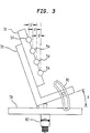
- the array support member 56 includes a pivotal member 76, a fixed member 78, and a clamp 80 which are shown in more detail in FIG. 3.
- Each of the lasers 52 is optically coupled to a separate one of the optical fibers 54 at an input end of the fiber 54. Output ends of the fibers 54 are held in the array support member 56 at a predetermined distance from each other. Output light beams 72 (shown by dashed lines) from each of the optical fibers 54 pass through the collimating lens 58 and emerge as collimated beams 74.
- the collimated beams 74 are reflected by the stationary mirror 60 and scanned by the galvanometer 62 across the F-Theta lens 64.
- the F-Theta lens 64 focuses the beams 74 along a focal plane that is coincident with a plane of the dye-donor sheet (not shown for purposes of clarity) which overlies the receiver 68. These focused beams are shown as the beams 70.
- the printer 50 produces a desired image on the receiver 68 by transferring dots of dye onto the receiver 68 from the overlying dye-donor sheet. Transfer of dots of dye occurs when concentrated beams 70 of laser-produced light heat localized portions of the dye-donor sheet and cause a sublimation of dots of dye on the sheet in the manner described in the above mentioned U.S. Patent Application Serial No. 457,593.
- An output light level of each of the lasers 52 is modulated in accordance with image data that is fed to the printer 50 from a conventional image source (not shown).
- a modulating system assigns image data to various channels. Each channel is associated with one of the lasere 52. In this manner, a portion of the image is produced by each of the lasers 52.
- a modulating system of this type is described in detail in U.S. Patent Application Serial No. 451,655 (S. H. Baek et al.), entitled "Thermal Printers, which is assigned to the assignee of the present patent application and is incorporated herein by reference.
- the printer 50 has substantial advantages over the printer 20 of FIG. 1. Specifically, the printer 50 is faster and simpler. The printer 50 generates a plurality of lines of an image substantially simultaneously. Additionally, the printer 50 has fewer optical elements than the printer 20 of FIG. 1 and therefore has a lower cost.
- FIG. 3 there is shown an enlarged end view of the array support member 56 of FIG. 2 with the cover plate 57 removed for purposes of clarity.
- This end view helps clarify the means by which the printer 50 produces images in a multi-line mode (as compared to the printer 20 of FIG. 1 which operates in a single line mode).
- the optical fibers 54 are aligned at an angle A. This is because the array support member 56 is held by the pivotal member 76.
- the pivotal member 76 is supported on the fixed member 78 and is held in a desired angular position by the clamp 80.
- a micrometer adjuster 82 sets the angular position of the pivotal member 76.
- a horizontal spacing d between centerlines of the optical fibers 54 is correspondingly varied.
- the distance d is also made small. It is important that the distance d be kept small when it is desired to produce a high resolution image, i.e., 2000 dots per inch or greater.
- the beams 70 are scanned vertically relative to the receiver 68.
- the beams 70 are displaced horizontally from each other by the distance d of FIG. 3, i.e., the horizontal spacing of the output ends of the optical fibers 54.
- d of FIG. 3 i.e., the horizontal spacing of the output ends of the optical fibers 54.
- Each of the beams 70 has a different vertical position relative to the receiver at any given moment.
- the channel oriented modulating described in the above mentioned U.S. Patent Application No. 451,655 compensates for these variations in vertical position of the beams 70.
- Modulating data to each of the lasers 52 is delivered with a different predetermined time delay. Each time delay for a particular one of the beams 70 corresponds to a time needed for that particular beam to reach a reference spot on the receiver 68. Thus each of the beams 70 produces a desired portion of the image at a desired vertical location on the receiver 68.
- An image is produced on the receiver 68 as a collection of pixels.
- the receiver is a 35 mm slide.
- the length and width of the elide are not always exactly the same. Consequently, the pixels which make up the image on the transparency are not square.
- the pixels have essentially the same aspect ratio as a 35mm slide, i.e., 1:1.25.
- the printer 50 is designed to produce an image with a nominal resolution of 4000 dots per inch.
- the modulating system produces discrete changes in light level at a rate that corresponds to 4000 changes per inch in the vertical direction.
- the horizontal spacing d between the beams 70 must therefore produce 4000/1.25 or 3200 beams per inch.
- the distance d between the centerlines of the optical fibers 54 of FIG. 3 must 10 microns or less in order to achieve a nominal image resolution of 4000 dots per inch.
- the optical fiber support member 56 and the optical fibers 54 are arranged in an array of the type described in U.S. Patent No. 4,911,526 (Hsu et al.), which patent is assigned to the assignee of the present application and is incorporated herein by reference.
- the optical fibers are positioned in grooves which are 20 microns apart.
- the fiber support member is positioned so that the angle A is sufficient to provide a horizontal spacing between the optical fibers of 10 microns.
- the printer 50 it is desirable to produce a controlled amount of overlap of the dots in the image. This effect is readily achieved by changing the angle A to produce a desired amount of overlap.
- the printer 50 is shown in FIGS. 2 and 3 (for purposes of clarity) with only four lasers 52 and four optical fibers 54.
- the printer has up to about thirty five lasers 52 and a corresponding number of optical fibers 54.
- a collimating lens such as an Olympus AV8414 with a focal length of 8.42 mm, N.A. 0.14 and a 700 micron radius field of view on its focal plane is suitable for use in the preferred embodiment of the present invention.
- the printer 50 has a speed increase of up to 35 times. This is because thirty five lines of an image are produced with each vertical scan.
- Each of the lasers 52 is a separate unit which is separately modulated. This arrangement results in image quality that is equal to that obtainable with single laser printers. This is not necessarily the case with some prior art printers that use laser diode arrays as a light source for generating images in a multi-line mode.
- laser diode arrays are used in a printer, there is thermal cross-talk between the lasers. In other words, the closely spaced lasers in the array are effected by heat generated by adjacent lasers in the array. This thermal cross-talk reduces image quality.
- Some laser-diode-array printers employ complex compensating schemes to reduce the adverse effects of thermal cross-talk.
- the lasers 52 are spaced a substantial distance from each other and are therefore thermally independent. Consequently, complex compensation schemes such as those used in laser-diode-array printers are not required in the printer 50.
- the inventive principles of the present invention to build the printer 50 with a smaller or greater number of lasers 52.
- a printer 50 with a smaller number of lasers 52 can be made at a relatively low cost, but will operate at a relatively lower speed.
- the printer 50 with a large number of lasers 52 is more expensive to build, but it can operate at a higher speed.
- the present invention accommodates any number of desirable design balances between cost of the printer 50 and speed of its operation. This is a very desirable design feature for a printer intended for use in office settings.
- the beams 72 emerging form the output ends of the optical fibers 54 are circular in cross section. This is because the optical fibers 54 are optically coupled to their respective laser 52. In this arrangement, light from the lasers 52 does not take on an elliptical cross-section, as is the case in the prior art printer 20 of FIG. 1. Because the beams 72 have a circular cross section, there is no need for the cylindrical lens 26 and the second collimating lens 28 of the prior art printer 20.
- the printer 50 is particularly useful applications in which the dye-donor sheet contains dyes which require high energy levels for transfer.
- the optical fibers must be multi-mode fibers to assure a sufficient amount of energy transfer from the lasers 52 to the dye-donor sheet. Multi-mode fibers produce some divergence of the beams 72. But, because the output ends of the optical fibers 54 are so closely spaced, a single collimating lens 58 is sufficient to perform all of the required collimating functions for the printer 50.
- the inventive printer 50 is made simpler than the prior art printer 20 in that a less complex optical system can be used.
- elimination of multiple lens produces substantial improvement in cost savings and in size reduction.
- the printer 50 has a wider range of application than the printer 20 of FIG. 1.
- the printer 50 is useful in producing images with silver halide systems. This is because a laser coupled to a small diameter optical fiber (such as the combination of the laser 52 and the optical fiber 54) results in a filtering phenomenon related to spontaneous emission. This filtering effect produces a particularly high contrast ratio for the laser-produced beams 70.
- the contrast ratio of the beam 40 of FIG. 1 is typically limited to 30 to 1, i.e., the maximum light level of the beam 40 is no more than 30 times greater than the minimum light level of the beam 40.
- a 30 to 1 contrast ratio is sufficient for thermal printing with dye-donor sheets which have dyes that sublime at a well-defined threshold energy level.
- a 30 to 1 contrast ratio is not sufficient to produce a high quality in a silver halide system.
- a typical image requires a contrast ratio of 100 to 1 or greater.
- the printer 50 is capable of producing the beams 70 with a contrast ratio of 300 to 1.
- the printer 50 is readily capable of producing images in a silver halide system.
- inventive printer may be used to produce images on opaque and large sized receivers.
- inventive printer may be operated with rotating prisms and various other forms of scanning devices instead of the beam scanning galvanometer shown above.
Landscapes
- Health & Medical Sciences (AREA)
- General Health & Medical Sciences (AREA)
- Toxicology (AREA)
- Electronic Switches (AREA)
- Dot-Matrix Printers And Others (AREA)
- Laser Beam Printer (AREA)
- Mechanical Optical Scanning Systems (AREA)
Applications Claiming Priority (2)
| Application Number | Priority Date | Filing Date | Title |
|---|---|---|---|
| US787283 | 1985-10-15 | ||
| US78728391A | 1991-11-04 | 1991-11-04 |
Publications (2)
| Publication Number | Publication Date |
|---|---|
| EP0541460A2 true EP0541460A2 (fr) | 1993-05-12 |
| EP0541460A3 EP0541460A3 (en) | 1994-05-18 |
Family
ID=25140984
Family Applications (1)
| Application Number | Title | Priority Date | Filing Date |
|---|---|---|---|
| EP19920420389 Withdrawn EP0541460A3 (en) | 1991-11-04 | 1992-10-29 | Multiple beam laser printer |
Country Status (2)
| Country | Link |
|---|---|
| EP (1) | EP0541460A3 (fr) |
| JP (1) | JPH05221013A (fr) |
Cited By (4)
| Publication number | Priority date | Publication date | Assignee | Title |
|---|---|---|---|---|
| EP0915761A4 (fr) * | 1995-12-06 | 1999-12-08 | Markem Corp | Marquage de pieces par balayage |
| WO2000044161A3 (fr) * | 1999-01-26 | 2002-01-17 | Presstek Inc | Système d'imagerie pompé par diode à plusieurs faisceaux |
| US7215453B2 (en) | 2004-12-23 | 2007-05-08 | Avago Technologies General Ip (Singapore) Pte. Ltd. | Optical system having extended angular scan range |
| JP2014507017A (ja) * | 2011-03-01 | 2014-03-20 | アプライド プレシジョン インコーポレイテッド | レーザビーム選択器 |
Families Citing this family (2)
| Publication number | Priority date | Publication date | Assignee | Title |
|---|---|---|---|---|
| JP4123714B2 (ja) | 2000-12-11 | 2008-07-23 | コニカミノルタビジネステクノロジーズ株式会社 | 画像形成装置 |
| JP6997469B2 (ja) * | 2016-07-17 | 2022-01-17 | アイオー テック グループ リミテッド | レーザー励起材料分注のためのキットおよびシステム |
Family Cites Families (5)
| Publication number | Priority date | Publication date | Assignee | Title |
|---|---|---|---|---|
| JPS63217763A (ja) * | 1987-03-06 | 1988-09-09 | Hitachi Ltd | 光プリンタ |
| US4884857A (en) * | 1987-11-09 | 1989-12-05 | International Business Machines Corporation | Scanner for use in multiple spot laser electrophotographic printer |
| US4870652A (en) * | 1988-07-08 | 1989-09-26 | Xerox Corporation | Monolithic high density arrays of independently addressable semiconductor laser sources |
| US4911526A (en) * | 1988-10-07 | 1990-03-27 | Eastman Kodak Company | Fiber optic array |
| JPH0593878A (ja) * | 1991-10-01 | 1993-04-16 | Hitachi Koki Co Ltd | 多ビームによる光記録装置 |
-
1992
- 1992-10-29 JP JP29157292A patent/JPH05221013A/ja active Pending
- 1992-10-29 EP EP19920420389 patent/EP0541460A3/en not_active Withdrawn
Cited By (8)
| Publication number | Priority date | Publication date | Assignee | Title |
|---|---|---|---|---|
| US6037968A (en) * | 1993-11-09 | 2000-03-14 | Markem Corporation | Scanned marking of workpieces |
| EP0915761A4 (fr) * | 1995-12-06 | 1999-12-08 | Markem Corp | Marquage de pieces par balayage |
| WO2000044161A3 (fr) * | 1999-01-26 | 2002-01-17 | Presstek Inc | Système d'imagerie pompé par diode à plusieurs faisceaux |
| US6452623B2 (en) | 1999-01-26 | 2002-09-17 | Presstek | Multiple-beam, diode-pumped imaging system |
| KR100385043B1 (ko) * | 1999-01-26 | 2003-05-23 | 프레스텍, 인크. | 다중 빔, 다이오드 펌핑 화상 형성 장치 |
| US7215453B2 (en) | 2004-12-23 | 2007-05-08 | Avago Technologies General Ip (Singapore) Pte. Ltd. | Optical system having extended angular scan range |
| JP2014507017A (ja) * | 2011-03-01 | 2014-03-20 | アプライド プレシジョン インコーポレイテッド | レーザビーム選択器 |
| US9606342B2 (en) | 2011-03-01 | 2017-03-28 | Ge Healthcare Bio-Sciences Corp. | Laser beam selectors |
Also Published As
| Publication number | Publication date |
|---|---|
| EP0541460A3 (en) | 1994-05-18 |
| JPH05221013A (ja) | 1993-08-31 |
Similar Documents
| Publication | Publication Date | Title |
|---|---|---|
| US4878066A (en) | Beam scanner with distortion correction | |
| US6836278B2 (en) | Optical scanning apparatus using a plurality of laser beams | |
| EP0179554B1 (fr) | Système d'enregistrement d'images en demi-teintes | |
| KR100374271B1 (ko) | 다중 빔 주사 광학 시스템 및 그것을 이용한 화상 형성 장치 | |
| US4070089A (en) | Two dimensional laser scanner with movable cylinder lens | |
| EP0573375B1 (fr) | Techniques d'impression utilisant les diodes lasers multiples | |
| US5808656A (en) | Arrangement and process for generating a matrix image on a photosensitive recording substrate | |
| US5550668A (en) | Multispot polygon ROS with maximized line separation depth of focus | |
| JP2002139693A (ja) | 画像形成システムで使用する照明システム | |
| US5463418A (en) | Plural-beam scanning optical apparatus | |
| JP3693190B2 (ja) | ラスタ走査装置における光線の方向を調整する装置 | |
| JP4391648B2 (ja) | ラスタ出力スキャナ画像形成システム | |
| US4884857A (en) | Scanner for use in multiple spot laser electrophotographic printer | |
| EP0541460A2 (fr) | Imprimante laser à faisceaux multiples | |
| JP2000000999A (ja) | レ―ザプリンタおよび該レ―ザプリンタの制御方法 | |
| JP3315610B2 (ja) | 走査光学装置 | |
| US4258395A (en) | Document scanning system | |
| US6101018A (en) | Light beam scanning optical apparatus | |
| US5392060A (en) | Half tone laser recording apparatus | |
| US20050157160A1 (en) | Parallel beam to beam uniformity correction | |
| US5142403A (en) | ROS scanner incorporating cylindrical mirror in pre-polygon optics | |
| JP4632751B2 (ja) | 光走査装置 | |
| JPH08318640A (ja) | 光バープリントヘッドを備えた無レンズ印刷装置 | |
| US5854705A (en) | Micropositioned laser source for raster output scanners | |
| EP0782928B1 (fr) | Imprimante xérographique en couleur avec des séries linéaires multiples de lasers à émission par la surface avec des longeurs d'onde similaires |
Legal Events
| Date | Code | Title | Description |
|---|---|---|---|
| PUAI | Public reference made under article 153(3) epc to a published international application that has entered the european phase |
Free format text: ORIGINAL CODE: 0009012 |
|
| AK | Designated contracting states |
Kind code of ref document: A2 Designated state(s): DE FR GB |
|
| PUAL | Search report despatched |
Free format text: ORIGINAL CODE: 0009013 |
|
| AK | Designated contracting states |
Kind code of ref document: A3 Designated state(s): DE FR GB |
|
| 17P | Request for examination filed |
Effective date: 19941027 |
|
| 17Q | First examination report despatched |
Effective date: 19951123 |
|
| 18D | Application deemed to be withdrawn |
Effective date: 19960404 |