EP0541730A1 - Panneau d'affichage d'informations telles que des messages publicitaires - Google Patents
Panneau d'affichage d'informations telles que des messages publicitaires Download PDFInfo
- Publication number
- EP0541730A1 EP0541730A1 EP91919938A EP91919938A EP0541730A1 EP 0541730 A1 EP0541730 A1 EP 0541730A1 EP 91919938 A EP91919938 A EP 91919938A EP 91919938 A EP91919938 A EP 91919938A EP 0541730 A1 EP0541730 A1 EP 0541730A1
- Authority
- EP
- European Patent Office
- Prior art keywords
- panel
- information
- frame
- engines
- sector
- Prior art date
- Legal status (The legal status is an assumption and is not a legal conclusion. Google has not performed a legal analysis and makes no representation as to the accuracy of the status listed.)
- Granted
Links
- 230000005540 biological transmission Effects 0.000 claims description 4
- 238000006073 displacement reaction Methods 0.000 claims description 4
- 230000007246 mechanism Effects 0.000 claims description 2
- 239000002985 plastic film Substances 0.000 claims description 2
- 230000008859 change Effects 0.000 abstract description 6
- 238000004590 computer program Methods 0.000 abstract description 2
- 238000005096 rolling process Methods 0.000 abstract 2
- 230000001105 regulatory effect Effects 0.000 abstract 1
- 238000004804 winding Methods 0.000 description 5
- 238000003825 pressing Methods 0.000 description 4
- 230000000903 blocking effect Effects 0.000 description 1
- 230000008878 coupling Effects 0.000 description 1
- 238000010168 coupling process Methods 0.000 description 1
- 238000005859 coupling reaction Methods 0.000 description 1
- 239000000463 material Substances 0.000 description 1
- 230000004048 modification Effects 0.000 description 1
- 238000012986 modification Methods 0.000 description 1
- 239000011295 pitch Substances 0.000 description 1
- 239000003381 stabilizer Substances 0.000 description 1
- 230000001360 synchronised effect Effects 0.000 description 1
- 230000000007 visual effect Effects 0.000 description 1
Images


Classifications
-
- G—PHYSICS
- G09—EDUCATION; CRYPTOGRAPHY; DISPLAY; ADVERTISING; SEALS
- G09F—DISPLAYING; ADVERTISING; SIGNS; LABELS OR NAME-PLATES; SEALS
- G09F11/00—Indicating arrangements for variable information in which the complete information is permanently attached to a movable support which brings it to the display position
- G09F11/18—Indicating arrangements for variable information in which the complete information is permanently attached to a movable support which brings it to the display position the display elements being carried by belts, chains, or the like other than endless
-
- G—PHYSICS
- G09—EDUCATION; CRYPTOGRAPHY; DISPLAY; ADVERTISING; SEALS
- G09F—DISPLAYING; ADVERTISING; SIGNS; LABELS OR NAME-PLATES; SEALS
- G09F7/00—Signs, name or number plates, letters, numerals, or symbols; Panels or boards
- G09F2007/007—Signs without covering windows
Definitions
- the present invention relates to a panel designed specifically for displaying information, such as for example advertising messages, with the characteristic that such messages may be changed, by means of a suitable electronic program, such that during a certain length of time, such as a sports match, the advertisements appearing on a certain panel may change one or several times, whereby several advertisers are able to use the same panel.
- the panel being described may also be used for displaying any other information requiring similar characteristics.
- the applicant is currently in a position to register a number of Patents as a result of an application deposited in France in 1984.
- the said application describes and claims a display system for information such as advertising messages, specially designed to be used in sporting events, such as for example in football fields, basketball pitches and the like, which events are broadcast on at least one television channel and where a number of panels are used as display elements, conveniently located in order to be picked up by the cameras.
- each camera has an element which is activated by a visual indicator established on each of the display panels, such that using appropriate means the time for which each image remains on the panel can be controlled, thereby allowing advertising costs to be dependant on the time for which the advertisements remain on the screen or allowing such periods to be established previously, such that when a certain advertisement or message has appeared on the screen for the agreed length of time, the message on the said display panel or group of display panels changes.
- the display panel for information such as advertising messages proposed by the invention is particularly useful for putting into practice the display system referred to in the previous paragraph, although the said panel may obviously also be used in display systems wherein the length of time for which the messages appear on the panels is contracted on the basis of real time of display on the panels rather than on the basis of the time for which they appear on the television screens connected to the channel or channels broadcasting the event.
- the panels being described may be used in any practical circumstance in which it is desired to display messages which change in time.
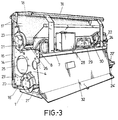
- the display panel proposed by the invention is comprised by a base provided with wheels for sliding the panel as a whole along rails which allow perfect longitudinal interconnection between modules, such that various adjacent modules may together make up a single message or advertisement, on which base is mounted a frame comprised by two parallel end plates, being vertically elongated and joined to each other at the front by means of a plurality of cross bars placed on the same plane, whereas at the rear the said plates are joined by means of a frame wherein is established a platform for holding the components of the electronic circuit of the panel, and to which are joined doors for accessing such components.
- rollers are established within the mentioned frame, specifically between the two end plates, two of which rollers are free to rotate whilst the other two are driven by engines, the two freely-rotating rollers occupying the imaginary upper and lower front corners of the panel, between which will be established the operative sector of the laminar body which actually carries the message, whereas the engine-driven rollers, which obviously rotate in opposite directions, are designed for winding and unwinding the said laminar body.
- the engines for driving the winding rollers are coupled coaxially thereto, and must in consequence be located outside the module, for which purpose it is foreseen, as a further characteristic of the invention, that the said rollers are out of alignment both laterally and transversally, such that, by means of inverse arrangement of the side plates in adjacent modules, the engines of one module will be housed in the empty spaces of the adjacent module, obviously crossing the corresponding side plate, and vice versa.
- each module has been foreseen, in which case the said engines are coupled to the winding rollers through transmission pulleys and belts rather than axially.
- the frame is adjustably mounted on the base and is provided with blocking means in a plurality of positions, such that the front surface of the said frame, on which is established the operative sector of the continuous laminar body which carries the messages, may adopt a vertical or slanting position, with a varying angle of inclination.
- the structure described is complemented with an electronic circuit controlled by a microprocessor, which establishes the times at which the information appearing on the panel should change, and which activates the engines in one or the other direction for the amount of time necessary to the change the information to one of the many which may be stored in a single panel, although the said microprocessor may obviously be substituted by a manual or remote control or any other means to act either directly or remotely on the module.
- the information display panel being described is formed by a base (1), provided with perimetrally grooved wheels (2) for displacement on rails (3), on which are established a plurality of panels in longitudinal alignment and duly coupled to one another, the said base (1) comprising the supporting structure for a frame consisting of a pair of side plates (4), stiffened by means of a plurality of mountings (5) which are coupled at the ends, in a coplanar arrangement with respect to the front edge of plates (4), specifically by means of screws which pass through holes (6) operatively provided on the said plates, the said frame being complemented by a rear upper frame (7) likewise established between the plates (4) and including a platform (8) wherein are located the electrical and electronic components of the panel which will be referred to hereinafter.
- the said frame is adjustably mounted on base (1), for which purpose it includes, a toothed (10) sector (9) coupled to one of its ends and wherein selectively plays a lock (11) mounted in box (12) which is in turn coupled to one of the ends of the frame (7), which, together with the rest of the body, is adjustably mounted on base (1), specifically by means of bearings (13).
- a rectangular plate (14) is fastened to mountings (5), immediately in front of which there is established a padded body (15), of the same rectangular shape, and in front again a plastic sheet (16), likewise having the same rectangular shape and constituting what will be the operative surface of the panel, over which slides a laminar body (17) which carryies the information and is suitably guided by a pair of rollers (18-18'), coupled free to turn on the ends of the front edge of plates (4), specifically in apertures (19) and with the aid of shaft screws (20), the ends of which laminar body (17) are wound on respective rollers (21-21') fastened to one of the end plates (4) of the frame, projecting outside the panel, as shown specifically in figure 2, the two engines (22-22') being duly synchronized such that when the laminar body (17) is unwound at one of the rollers (21) it will be wound in the same amount at the other, and vice versa.
- Each end plate (4) of the frame includes a pair of pressings (23-23') for engaging the engines (22-22') with the aid of respective supports (24-24'), in addition to which the said pressings (23-23') are out of alignment both vertically and transversally, the plates further including a large aperture (25) and a channelling (26) which are likewise out of alignment with respect to the previously mentioned pressings (23), such that by arranging the plates (4) of one module inverted with respect to the adjacent one, and as is likewise observed in figure 2, the engines (24) of one module or panel are out of alignment with respect to those of the other and penetrate and are housed in the empty spaces left by the rollers (21) in the other, through the said apertures (25) and channelling (26).
- the mentioned engines (22) with their corresponding wiring (27) are jointly controlled for each and every one of the modules from a main control box not shown in the drawing, through various auxiliary boxes, by means of a computer program established in the corresponding microprocessor, which sends the corresponding signals to an electronic box or panel (28) provided on platfrom (8), with which works a feeding transformer (29), stabilisers or any other suitable element to ensure optimum feeding conditions, and the corresponding terminals (30) for connection of the engines.
- the structure described is completed with a cover wherein is defined a fixed sector (31) and two adjustable sectors, a rear sector (32) allowing access to platform (8) where the electric and electronic components are located, and a front sector (33) which partially overlaps the marginal upper area of the operative sector of the laminar body (17) carrying the information and below which may be extracted a waterproof sheet for protection of the said laminar body when same is not in use.
- the module is likewise closed at the rear below the adjustable cover (32), specifically through frame parts (34) and (35) which can be clearly seen in figure 1.
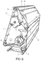
- the upper (31) and rear (32) covers are made as a significantly inclined single cover (38), the module adopting a trapezial, almost triangular, profile as observed especially in figure 6, for which, and as likewise observed in the said figure, it is necessary that the winding roller (21), located on an upper level, should adopt a considerably lower position than in the previous case, and be furthermore displaced towards the front wall of the module.
Landscapes
- General Physics & Mathematics (AREA)
- Engineering & Computer Science (AREA)
- Theoretical Computer Science (AREA)
- Physics & Mathematics (AREA)
- Displays For Variable Information Using Movable Means (AREA)
- Illuminated Signs And Luminous Advertising (AREA)
- Control Of Indicators Other Than Cathode Ray Tubes (AREA)
- Display Devices Of Pinball Game Machines (AREA)
- Controls And Circuits For Display Device (AREA)
- Adjustment And Processing Of Grains (AREA)
- Disintegrating Or Milling (AREA)
- Crushing And Pulverization Processes (AREA)
- Filling Or Discharging Of Gas Storage Vessels (AREA)
- Optical Record Carriers And Manufacture Thereof (AREA)
- Vessels, Lead-In Wires, Accessory Apparatuses For Cathode-Ray Tubes (AREA)
- Vehicle Waterproofing, Decoration, And Sanitation Devices (AREA)
- Management, Administration, Business Operations System, And Electronic Commerce (AREA)
- Control Of Vending Devices And Auxiliary Devices For Vending Devices (AREA)
- Digital Computer Display Output (AREA)
- Train Traffic Observation, Control, And Security (AREA)
- Chemical And Physical Treatments For Wood And The Like (AREA)
Abstract
Applications Claiming Priority (3)
| Application Number | Priority Date | Filing Date | Title |
|---|---|---|---|
| ES09101311A ES2088322B1 (es) | 1991-05-30 | 1991-05-30 | Panel de exhibicion de informaciones tales como mensajes publicitarios. |
| ES9101311 | 1991-05-30 | ||
| PCT/ES1991/000073 WO1992022052A1 (fr) | 1991-05-30 | 1991-11-08 | Panneau d'affichage d'informations telles que des messages publicitaires |
Publications (2)
| Publication Number | Publication Date |
|---|---|
| EP0541730A1 true EP0541730A1 (fr) | 1993-05-19 |
| EP0541730B1 EP0541730B1 (fr) | 1994-07-20 |
Family
ID=8272547
Family Applications (1)
| Application Number | Title | Priority Date | Filing Date |
|---|---|---|---|
| EP91919938A Expired - Lifetime EP0541730B1 (fr) | 1991-05-30 | 1991-11-08 | Panneau d'affichage d'informations telles que des messages publicitaires |
Country Status (29)
| Country | Link |
|---|---|
| EP (1) | EP0541730B1 (fr) |
| JP (1) | JPH0731473B2 (fr) |
| CN (1) | CN1028387C (fr) |
| AT (1) | ATE108933T1 (fr) |
| AU (1) | AU662498B2 (fr) |
| BG (1) | BG60930B1 (fr) |
| BR (1) | BR9106953A (fr) |
| CA (1) | CA2087709C (fr) |
| CS (1) | CS163592A3 (fr) |
| DE (1) | DE69103013T2 (fr) |
| DK (1) | DK0541730T3 (fr) |
| ES (1) | ES2088322B1 (fr) |
| FI (1) | FI100622B (fr) |
| HU (1) | HUT63265A (fr) |
| IE (1) | IE65343B1 (fr) |
| IL (1) | IL102031A0 (fr) |
| IS (1) | IS3861A (fr) |
| MA (1) | MA22536A1 (fr) |
| MC (1) | MC2256A1 (fr) |
| NO (1) | NO300946B1 (fr) |
| NZ (1) | NZ242691A (fr) |
| PL (1) | PL167654B1 (fr) |
| PT (1) | PT100500B (fr) |
| TR (1) | TR26022A (fr) |
| TW (1) | TW235357B (fr) |
| UY (1) | UY23425A1 (fr) |
| WO (1) | WO1992022052A1 (fr) |
| YU (1) | YU52592A (fr) |
| ZA (1) | ZA923703B (fr) |
Cited By (5)
| Publication number | Priority date | Publication date | Assignee | Title |
|---|---|---|---|---|
| FR2705816A1 (fr) * | 1993-05-24 | 1994-12-02 | Tabary Guy Albert C | Modules d'affichage d'images publicitaires et ensemble d'affichage. |
| WO1995026021A1 (fr) * | 1994-03-21 | 1995-09-28 | Flagtime Inc. | Appareil d'affichage a cassette amovible |
| GB2291249A (en) * | 1992-04-11 | 1996-01-17 | Visual Communication Sys Ltd | A display apparatus |
| WO1999038147A1 (fr) * | 1998-01-26 | 1999-07-29 | Humbert Michalon | Dispositif d'affichage sequentiel permettant la fixation individuelle de plusieurs affiches sur un film support |
| WO2005055179A1 (fr) * | 2003-12-02 | 2005-06-16 | Leif Bertil Hjert | Panneau publicitaire interchangeable |
Families Citing this family (1)
| Publication number | Priority date | Publication date | Assignee | Title |
|---|---|---|---|---|
| CN110544446A (zh) * | 2019-07-22 | 2019-12-06 | 吉林工程技术师范学院 | 一种宣传装置 |
Family Cites Families (9)
| Publication number | Priority date | Publication date | Assignee | Title |
|---|---|---|---|---|
| DE521349C (de) * | 1931-03-20 | Alpine Akt Ges Eisengiesserei | Schlagstiftmuehle mit zwei zwischen zwei umlaufenden Schlagscheiben angeordneten Mahlscheiben | |
| DE923169C (de) * | 1950-10-19 | 1955-02-03 | Kohlenscheidungs Ges M B H | Schlagradmuehle |
| DE1026159B (de) * | 1956-03-31 | 1958-03-13 | Kohlenscheidungs Ges Mit Besch | Laeufer fuer Schleudermuehlen |
| DE1253562B (de) * | 1965-12-08 | 1967-11-02 | Miag Muehlenbau | Prall- und Schaelmuehle mit mindestens zwei um eine lotrechte Achse umlaufenden Schleuderraedern |
| JPS4330599Y1 (fr) * | 1967-12-20 | 1968-12-13 | ||
| DE1814751A1 (de) * | 1968-12-14 | 1970-06-25 | Miag Muehlenbau & Ind Gmbh | Prall- und Schaelmuehle |
| IT206703Z2 (it) * | 1985-08-02 | 1987-10-01 | Cavisedo Srl | Segnalatore di percorso per veicoli di trasporto pubblico particolamente per autobus |
| JPH02122843A (ja) * | 1988-10-31 | 1990-05-10 | Kurimoto Ltd | 竪型衝撃式破砕機 |
| US5003717A (en) * | 1989-09-18 | 1991-04-02 | Everbrite, Inc. | Changeable information scroll sign |
-
1991
- 1991-05-30 ES ES09101311A patent/ES2088322B1/es not_active Expired - Fee Related
- 1991-11-08 BR BR919106953A patent/BR9106953A/pt not_active IP Right Cessation
- 1991-11-08 JP JP4500034A patent/JPH0731473B2/ja not_active Expired - Fee Related
- 1991-11-08 DE DE69103013T patent/DE69103013T2/de not_active Expired - Fee Related
- 1991-11-08 MC MC91ES9100073D patent/MC2256A1/fr unknown
- 1991-11-08 HU HU921830A patent/HUT63265A/hu unknown
- 1991-11-08 CA CA002087709A patent/CA2087709C/fr not_active Expired - Fee Related
- 1991-11-08 AT AT91919938T patent/ATE108933T1/de not_active IP Right Cessation
- 1991-11-08 AU AU89190/91A patent/AU662498B2/en not_active Ceased
- 1991-11-08 EP EP91919938A patent/EP0541730B1/fr not_active Expired - Lifetime
- 1991-11-08 WO PCT/ES1991/000073 patent/WO1992022052A1/fr not_active Ceased
- 1991-11-08 DK DK91919938.0T patent/DK0541730T3/da active
-
1992
- 1992-05-11 NZ NZ242691A patent/NZ242691A/xx unknown
- 1992-05-13 IS IS3861A patent/IS3861A/is unknown
- 1992-05-19 PT PT100500A patent/PT100500B/pt not_active IP Right Cessation
- 1992-05-20 YU YU52592A patent/YU52592A/sh unknown
- 1992-05-21 ZA ZA923703A patent/ZA923703B/xx unknown
- 1992-05-27 IL IL102031A patent/IL102031A0/xx unknown
- 1992-05-28 CN CN92104062A patent/CN1028387C/zh not_active Expired - Fee Related
- 1992-05-28 MA MA22823A patent/MA22536A1/fr unknown
- 1992-05-29 CS CS921635A patent/CS163592A3/cs unknown
- 1992-05-29 TR TR92/0549A patent/TR26022A/xx unknown
- 1992-06-01 UY UY23425A patent/UY23425A1/es unknown
- 1992-06-10 BG BG96449A patent/BG60930B1/bg unknown
- 1992-06-10 NO NO922278A patent/NO300946B1/no not_active IP Right Cessation
- 1992-06-25 FI FI922952A patent/FI100622B/fi active
-
1993
- 1993-01-20 IE IE921515A patent/IE65343B1/en not_active IP Right Cessation
- 1993-01-20 PL PL91296699A patent/PL167654B1/pl unknown
- 1993-04-29 TW TW082103321A patent/TW235357B/zh active
Non-Patent Citations (1)
| Title |
|---|
| See references of WO9222052A1 * |
Cited By (8)
| Publication number | Priority date | Publication date | Assignee | Title |
|---|---|---|---|---|
| GB2291249A (en) * | 1992-04-11 | 1996-01-17 | Visual Communication Sys Ltd | A display apparatus |
| GB2291249B (en) * | 1992-04-11 | 1996-07-03 | Visual Communication Sys Ltd | Display apparatus |
| GB2265997B (en) * | 1992-04-11 | 1996-07-03 | Visual Communication Sys Ltd | Display apparatus |
| FR2705816A1 (fr) * | 1993-05-24 | 1994-12-02 | Tabary Guy Albert C | Modules d'affichage d'images publicitaires et ensemble d'affichage. |
| WO1995026021A1 (fr) * | 1994-03-21 | 1995-09-28 | Flagtime Inc. | Appareil d'affichage a cassette amovible |
| WO1999038147A1 (fr) * | 1998-01-26 | 1999-07-29 | Humbert Michalon | Dispositif d'affichage sequentiel permettant la fixation individuelle de plusieurs affiches sur un film support |
| FR2774204A1 (fr) * | 1998-01-26 | 1999-07-30 | Humbert Michalon | Dispositif d'affichage sequentiel permettant la fixation individuelle, sans froissement, ni dechirures, ni decollement, de plusieurs affiches, directement sur un film support en polyester |
| WO2005055179A1 (fr) * | 2003-12-02 | 2005-06-16 | Leif Bertil Hjert | Panneau publicitaire interchangeable |
Also Published As
Similar Documents
| Publication | Publication Date | Title |
|---|---|---|
| EP2443621B1 (fr) | Dispositif d'affichage pliable | |
| EP0541730B1 (fr) | Panneau d'affichage d'informations telles que des messages publicitaires | |
| DE69506257T2 (de) | Vorrichtung zur selektiven anzeigung eines bildes aus einem satz solcher bilder | |
| US5946836A (en) | Variable display device | |
| DE69810634T2 (de) | Anzeigevorrichtungen | |
| WO2012003567A1 (fr) | Obturateur spatial variable pour dispositif d'affichage à del | |
| AU2009200836A1 (en) | Improvements Relating to Billboards | |
| US5896689A (en) | Bill posting device | |
| US5557868A (en) | Modules for displaying advertising images, and a display assembly | |
| WO2021255259A1 (fr) | Dispositif d'affichage | |
| DE19949835C2 (de) | Werbeträger-Einheit | |
| EP1787275B1 (fr) | Dispositif d'alternance d'images | |
| IE922756A1 (en) | Information display device | |
| DE102010009922B4 (de) | Vorrichtung zur Präsentation von Werbung oder von Gestaltungselementen an der Rückseite von stationären Flachbildschirmen | |
| DE1861832U (de) | Filmprojecktor mit auf einer flachen platte befestigten lagerboecken fuer die wellen der filmtransportrollen und filmfuehrungselementen. | |
| DE29810143U1 (de) | Informations- und/oder Werbevorrichtung | |
| DE9300294U1 (de) | Vorrichtung zum Beschauen von Großdiapositiven |
Legal Events
| Date | Code | Title | Description |
|---|---|---|---|
| PUAI | Public reference made under article 153(3) epc to a published international application that has entered the european phase |
Free format text: ORIGINAL CODE: 0009012 |
|
| 17P | Request for examination filed |
Effective date: 19920619 |
|
| AK | Designated contracting states |
Kind code of ref document: A1 Designated state(s): AT BE CH DE DK FR GB GR IT LI LU NL SE |
|
| ITCL | It: translation for ep claims filed |
Representative=s name: STUDIO BIANCHETTI |
|
| EL | Fr: translation of claims filed | ||
| 17Q | First examination report despatched |
Effective date: 19940104 |
|
| GRAA | (expected) grant |
Free format text: ORIGINAL CODE: 0009210 |
|
| AK | Designated contracting states |
Kind code of ref document: B1 Designated state(s): AT BE CH DE DK FR GB GR IT LI LU NL SE |
|
| REF | Corresponds to: |
Ref document number: 108933 Country of ref document: AT Date of ref document: 19940815 Kind code of ref document: T |
|
| REF | Corresponds to: |
Ref document number: 69103013 Country of ref document: DE Date of ref document: 19940825 |
|
| REG | Reference to a national code |
Ref country code: DK Ref legal event code: T3 |
|
| ITF | It: translation for a ep patent filed | ||
| ET | Fr: translation filed | ||
| REG | Reference to a national code |
Ref country code: GR Ref legal event code: FG4A Free format text: 3013654 |
|
| EAL | Se: european patent in force in sweden |
Ref document number: 91919938.0 |
|
| PLBE | No opposition filed within time limit |
Free format text: ORIGINAL CODE: 0009261 |
|
| STAA | Information on the status of an ep patent application or granted ep patent |
Free format text: STATUS: NO OPPOSITION FILED WITHIN TIME LIMIT |
|
| 26N | No opposition filed | ||
| NLS | Nl: assignments of ep-patents |
Owner name: ADTIME ACQUISITION HOLDING CO., INC. |
|
| PGFP | Annual fee paid to national office [announced via postgrant information from national office to epo] |
Ref country code: CH Payment date: 19981201 Year of fee payment: 8 |
|
| PG25 | Lapsed in a contracting state [announced via postgrant information from national office to epo] |
Ref country code: LI Free format text: LAPSE BECAUSE OF NON-PAYMENT OF DUE FEES Effective date: 19991130 Ref country code: CH Free format text: LAPSE BECAUSE OF NON-PAYMENT OF DUE FEES Effective date: 19991130 |
|
| PGFP | Annual fee paid to national office [announced via postgrant information from national office to epo] |
Ref country code: GB Payment date: 20000419 Year of fee payment: 9 |
|
| REG | Reference to a national code |
Ref country code: CH Ref legal event code: PL |
|
| PGFP | Annual fee paid to national office [announced via postgrant information from national office to epo] |
Ref country code: FR Payment date: 20001031 Year of fee payment: 10 |
|
| PG25 | Lapsed in a contracting state [announced via postgrant information from national office to epo] |
Ref country code: GB Free format text: LAPSE BECAUSE OF NON-PAYMENT OF DUE FEES Effective date: 20001108 |
|
| GBPC | Gb: european patent ceased through non-payment of renewal fee |
Effective date: 20001108 |
|
| PG25 | Lapsed in a contracting state [announced via postgrant information from national office to epo] |
Ref country code: FR Free format text: LAPSE BECAUSE OF NON-PAYMENT OF DUE FEES Effective date: 20020730 |
|
| REG | Reference to a national code |
Ref country code: FR Ref legal event code: ST |
|
| REG | Reference to a national code |
Ref country code: FR Ref legal event code: ST |
|
| PGFP | Annual fee paid to national office [announced via postgrant information from national office to epo] |
Ref country code: SE Payment date: 20030221 Year of fee payment: 12 Ref country code: NL Payment date: 20030221 Year of fee payment: 12 Ref country code: AT Payment date: 20030221 Year of fee payment: 12 |
|
| PGFP | Annual fee paid to national office [announced via postgrant information from national office to epo] |
Ref country code: GR Payment date: 20030226 Year of fee payment: 12 Ref country code: DK Payment date: 20030226 Year of fee payment: 12 |
|
| PGFP | Annual fee paid to national office [announced via postgrant information from national office to epo] |
Ref country code: DE Payment date: 20030228 Year of fee payment: 12 Ref country code: BE Payment date: 20030228 Year of fee payment: 12 |
|
| PGFP | Annual fee paid to national office [announced via postgrant information from national office to epo] |
Ref country code: LU Payment date: 20030310 Year of fee payment: 12 |
|
| PG25 | Lapsed in a contracting state [announced via postgrant information from national office to epo] |
Ref country code: LU Free format text: LAPSE BECAUSE OF NON-PAYMENT OF DUE FEES Effective date: 20031108 Ref country code: AT Free format text: LAPSE BECAUSE OF NON-PAYMENT OF DUE FEES Effective date: 20031108 |
|
| PG25 | Lapsed in a contracting state [announced via postgrant information from national office to epo] |
Ref country code: SE Free format text: LAPSE BECAUSE OF NON-PAYMENT OF DUE FEES Effective date: 20031109 |
|
| PG25 | Lapsed in a contracting state [announced via postgrant information from national office to epo] |
Ref country code: BE Free format text: LAPSE BECAUSE OF NON-PAYMENT OF DUE FEES Effective date: 20031130 |
|
| PG25 | Lapsed in a contracting state [announced via postgrant information from national office to epo] |
Ref country code: DK Free format text: LAPSE BECAUSE OF NON-PAYMENT OF DUE FEES Effective date: 20031201 |
|
| BERE | Be: lapsed |
Owner name: *ADTIME ACQUISITION HOLDING CO. INC. (UNE SOC. DE Effective date: 20031130 |
|
| PG25 | Lapsed in a contracting state [announced via postgrant information from national office to epo] |
Ref country code: NL Free format text: LAPSE BECAUSE OF NON-PAYMENT OF DUE FEES Effective date: 20040601 |
|
| PG25 | Lapsed in a contracting state [announced via postgrant information from national office to epo] |
Ref country code: DE Free format text: LAPSE BECAUSE OF NON-PAYMENT OF DUE FEES Effective date: 20040602 |
|
| PG25 | Lapsed in a contracting state [announced via postgrant information from national office to epo] |
Ref country code: GR Free format text: LAPSE BECAUSE OF NON-PAYMENT OF DUE FEES Effective date: 20040603 |
|
| EUG | Se: european patent has lapsed | ||
| REG | Reference to a national code |
Ref country code: DK Ref legal event code: EBP |
|
| NLV4 | Nl: lapsed or anulled due to non-payment of the annual fee |
Effective date: 20040601 |
|
| PG25 | Lapsed in a contracting state [announced via postgrant information from national office to epo] |
Ref country code: IT Free format text: LAPSE BECAUSE OF NON-PAYMENT OF DUE FEES;WARNING: LAPSES OF ITALIAN PATENTS WITH EFFECTIVE DATE BEFORE 2007 MAY HAVE OCCURRED AT ANY TIME BEFORE 2007. THE CORRECT EFFECTIVE DATE MAY BE DIFFERENT FROM THE ONE RECORDED. Effective date: 20051108 |