EP0541913A1 - Dispositif d'observation du déroulement de processus - Google Patents
Dispositif d'observation du déroulement de processus Download PDFInfo
- Publication number
- EP0541913A1 EP0541913A1 EP92114283A EP92114283A EP0541913A1 EP 0541913 A1 EP0541913 A1 EP 0541913A1 EP 92114283 A EP92114283 A EP 92114283A EP 92114283 A EP92114283 A EP 92114283A EP 0541913 A1 EP0541913 A1 EP 0541913A1
- Authority
- EP
- European Patent Office
- Prior art keywords
- tube
- stroboscope
- drive
- sight glass
- tubular
- Prior art date
- Legal status (The legal status is an assumption and is not a legal conclusion. Google has not performed a legal analysis and makes no representation as to the accuracy of the status listed.)
- Granted
Links
Images


Classifications
-
- G—PHYSICS
- G02—OPTICS
- G02B—OPTICAL ELEMENTS, SYSTEMS OR APPARATUS
- G02B7/00—Mountings, adjusting means, or light-tight connections, for optical elements
- G02B7/007—Pressure-resistant sight glasses
-
- B—PERFORMING OPERATIONS; TRANSPORTING
- B01—PHYSICAL OR CHEMICAL PROCESSES OR APPARATUS IN GENERAL
- B01J—CHEMICAL OR PHYSICAL PROCESSES, e.g. CATALYSIS OR COLLOID CHEMISTRY; THEIR RELEVANT APPARATUS
- B01J3/00—Processes of utilising sub-atmospheric or super-atmospheric pressure to effect chemical or physical change of matter; Apparatus therefor
- B01J3/004—Sight-glasses therefor
-
- C—CHEMISTRY; METALLURGY
- C23—COATING METALLIC MATERIAL; COATING MATERIAL WITH METALLIC MATERIAL; CHEMICAL SURFACE TREATMENT; DIFFUSION TREATMENT OF METALLIC MATERIAL; COATING BY VACUUM EVAPORATION, BY SPUTTERING, BY ION IMPLANTATION OR BY CHEMICAL VAPOUR DEPOSITION, IN GENERAL; INHIBITING CORROSION OF METALLIC MATERIAL OR INCRUSTATION IN GENERAL
- C23C—COATING METALLIC MATERIAL; COATING MATERIAL WITH METALLIC MATERIAL; SURFACE TREATMENT OF METALLIC MATERIAL BY DIFFUSION INTO THE SURFACE, BY CHEMICAL CONVERSION OR SUBSTITUTION; COATING BY VACUUM EVAPORATION, BY SPUTTERING, BY ION IMPLANTATION OR BY CHEMICAL VAPOUR DEPOSITION, IN GENERAL
- C23C14/00—Coating by vacuum evaporation, by sputtering or by ion implantation of the coating forming material
- C23C14/22—Coating by vacuum evaporation, by sputtering or by ion implantation of the coating forming material characterised by the process of coating
- C23C14/52—Means for observation of the coating process
Definitions
- a disk stroboscope of the type mentioned at the outset is already known and is driven in the center by a drive motor. Since a motor arranged in this way takes up a lot of space, the disk must be very large be dimensioned large so that there is still enough space on the side of the drive motor for a passage opening through which the process sequence in the vacuum chamber can be observed.
- the object of the invention is to find a simple, economical device by means of which process sequences, in particular process sequences in vacuum technology or evaporator boats, can easily be observed undisturbed over a long period of time.
- the invention solves the problems in that the rotating device for preventing contamination of the sight glass is designed as a cylindrical rotating body which is provided on one side with an inlet opening and on the other side, diametrically opposite, with an outlet opening.
- a device for observing process sequences is created in a simple and thus cost-saving manner, with which process sequences can be observed over a very long period of time without the contamination of the sight glass being expected. Since the motor can be provided outside of the vacuum chamber due to the advantageous design of the rotating device, there is the possibility of making the rotating device considerably smaller and thus more economical than before.
- the rotating device for preventing contamination of the sight glass is designed as a cylindrical tube which is provided with two diametrically opposite openings.
- the diametrically opposite openings are arranged on the transverse central plane and the tube is designed as a tube stroboscope which is rotatably mounted in a vacuum chamber.
- a large area can be observed in the vacuum chamber without there being any risk that the sight glass will become wet even after a long process time.
- precipitation only forms on the surface of the tube stroboscope.
- the use of a tubular stroboscope also offers the possibility of making the tube and the associated openings relatively long, so that several people can observe the working process at the same time by means of a tube stroboscope, in particular because the drive is arranged coaxially to the tube. This does not block the view behind the sight glass.
- tubular stroboscope is rotatably supported by means of a vacuum rotary leadthrough and is driven by a drive device.
- the tube stroboscope is driven by a motor which is provided outside the vacuum chamber and which is in drive connection with the tube via the vacuum rotary leadthrough. This makes it much easier to wire the motor.
- the tubular stroboscope prefferably connected to the motor via a magnetic coupling, a part of the magnetic coupling being provided in the vacuum chamber and another part of the magnetic coupling being provided outside the vacuum chamber.
- a gas-powered drive wheel is provided as the drive device, which is in drive connection with the tube.
- the drive device consists of at least one jet nozzle which is in drive connection with a drive disk having drive elements. This creates a drive device for the cylindrical tube with simple structural means, which can be easily integrated into the system.
- the drive device consists of at least one jet nozzle and a drive disk having numerous openings.
- the jet nozzle is arranged inclined with respect to the axis of rotation of the tubular stroboscope and / or the drive disk. This creates a very inexpensive, easy-to-install device for driving the tubular stroboscope.
- a tubular stroboscope that is only driven with the help of argon gas, i.e. without Electric motor runs (argon jet drive).
- argon jet drive argon jet drive
- the advantage of this device would be a certain overpressure of argon in the tube stroboscope itself. This argon cushion also counteracts severe contamination of the sight glass.
- an additional possibility is that a suction device is provided in the area of the sight glass and / or the tube stroboscope, via which dirt particles can be extracted from the receiving space of the tube stroboscope.
- a suction device is provided in the area of the sight glass and / or the tube stroboscope, via which dirt particles can be extracted from the receiving space of the tube stroboscope.
- the opening provided on the input side with respect to the beam path in the tube is smaller than the opening provided on the output side. In this way it is achieved that the process flow can be easily observed over a large area.
- the openings on the inlet and outlet sides are designed as slot openings, the opening on the inlet side being at least 0.5 mm and the outlet opening being between 1 and 60 mm in size. Contamination of the sight glass is effectively prevented by the relatively small opening.
- the large slit on the exit side gives you a correspondingly large field of view.
- the distance between the outer circumference of the tube stroboscope and the sight glass inner surface is at least 1 mm.
- the tube stroboscope consists of a cylindrical tube jacket, at the ends of which there is a disk with a hub, which are rotatably received in bearings provided in flanges.
- a possible variant of this device is the installation directly on a vacuum boiler with standard parts.
- These devices are located, for example, in vapor deposition systems in which foils are fed to a vapor deposition source at high winding speeds and are vaporized with aluminum.
- plastic films are coated up to a width of 3 m.
- the foils are wound into a tower of approx. 1 m in diameter.
- the evaporation process boat
- the stoboscope according to the invention is suitable for this purpose, it also being possible for several slits to be provided next to one another in the cylindrical tube of the stroboscope. This increases the stability of the pipe with simple means.
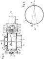
- 1 denotes a vacuum system or a vacuum boiler, which can consist of a cylindrical tube system 20.
- a vacuum vessel 1 On the vacuum vessel 1 there is a rectangular foot part 21 with which the vacuum vessel 1 is placed on the floor.
- a sight glass box 2 which is inclined with respect to the storage surface of the vacuum vessel 1, is attached to the vacuum vessel 1, with which, for example, one can look into the vacuum vessel 1 via a sight glass 3 attached to the sight glass box 2 and an evaporator boat 40 or can observe other parts or process sequences provided in the vacuum vessel 1 well.
- the sight glass box 2 consists of a cylindrical tube 4 'for receiving a tube stroboscope 4, which consists of a cylindrical tube jacket 41, at the ends of which there is a disk 5 with a hub 34.
- the tube 4 ' has on the right and left immediately next to the sight glass 3 two flanges 8 which are arranged coaxially and are mirror-symmetrical to the sight glass case 2.
- the flanges 8 are fixed to the pipe 4 'or welded or connected to it in some other way.
- the tube stroboscope 4 which fills the entire space between the two flanges 8, sits in the tube 4 'in the center between the two flanges 8.
- the tube stroboscope 4 has at least one, preferably two or more, opposite, small observation openings or longitudinal slots 24, 25 (see Figure 6).
- tube stroboscope 4 At the end of the tube stroboscope 4 (FIG. 2) there are coaxially arranged tube attachments 8 ', each with a receiving disc 5, which are welded or firmly connected to the tube stroboscope 4.
- This tubular stroboscope 4 is supported via vacuum rotary unions 13 (FIG. 2), which are accommodated concentrically in the two flanges 11 and a tube extension 7 arranged on the flange 8.
- One end of the cylindrical tube extension 7 is welded onto the flange 11.
- the rotary vacuum feedthrough 13 can be equipped with a plain bearing 37 (not shown in more detail).
- a flange 39 is provided on the upper end of a pipe socket 38, on which the sight glass 3 is fastened in a sealing manner.
- a flange 10 is arranged on the tube 7 and extends coaxially to the longitudinal central axis of the tube 4 '.
- a motor 15 with a clutch 6 is connected to the flange 10.
- the motor 15 has an axis 35.
- the central axis 36 running through the sight glass 3 intersects the axis 35 of the motor at an approximately right angle.
- the coupling 6 is in drive connection with the vacuum rotary feedthrough 13.
- the motor 15 drives the tube stroboscope 4 at a speed between 960 and 1200 rpm via the coupling 6, so that at least 16 images per second can be generated.
- a T-piece 12 with a nominal width of 100 mm is provided diametrically opposite the pipe socket 38, which is adapted to the cylindrical outer circumference of the boiler 1, so that the T-piece 12 is relatively close to the curve or can be brought up to the outer circumference of the boiler 1 according to FIG.
- the tube stroboscope 4 is provided, which, as already mentioned, is provided with two opposite longitudinal slots 24, 25 according to FIG. 6.
- the longitudinal slot 24 on the input side should be at least 0.5 mm in size, while the longitudinal slot 25 on the output side should be larger, for example between 1 mm and 60 mm, in particular 50 mm, in size. In this way it is prevented that a dirt film forms on the sight glass 3, since the dirt particles can now mainly be deposited on the cylindrical tubular stroboscope 4.
- the tubular stroboscope 4 is mounted via the vacuum rotary unions 13, which in turn are seated centrally in the flanges 11.
- the flange 11 can have a diameter between 100 and 150 mm, in particular 130 mm. This gives a very space-saving arrangement behind the sight glass 3 for the tube stroboscope 4.
- the bearings can be designed as slide bearings, in particular as deep groove ball bearings 18.
- the exemplary embodiment according to FIG. 5 differs from the exemplary embodiment according to FIG. 3 only in the special mounting and drive type of the tubular stroboscope 4, and according to this exemplary embodiment the tubular stroboscope 4 is also mounted via the two deep groove ball bearings 18, which in turn are centered in the aluminum blind flanges 11 a nominal size 100 can sit.
- the two flanges 11 made of Al are also closed with the vacuum seals 9 against the flanges 8.
- the flanges 11 are screwed onto the flanges 8 and thus sealed against the atmosphere.
- a flange 11 ′ is centrally connected on one side on the flange 11 to the tube extension 7, in which the motor 15 is received with a magnetic coupling 16, via which the tube stroboscope 4 is driven.
- a part 16 'of the magnetic coupling is coupled directly to the stroboscope 4 or the receiving disc 5 connected to it, while the other part 16''is on the left from the flange 11 outside the vacuum chamber 31 in the tube 7 and connected to the motor 15.
- the tubular stroboscope 4 is driven via the receiving disc 5, which is designed as a paddle wheel.
- the paddle wheel is charged with a gas jet, which is provided by jet nozzles 19 provided in the blind flanges 11 (see FIG. 4 b) and the Openings 27 is passed, which are provided in the disc 5.
- This causes the tube stroboscope 4 to rotate in a very cost-effective manner.
- the rotating parts, in particular the disk 5, can be provided with compensation bores.
- the stroboscope 4 is rotatably mounted directly behind the sight glass 3 in the vacuum vessel 1. Furthermore, it can be provided with a suction device in order to ensure, in the case of very strong vapor deposition, that the dust or the dirt particles that would otherwise be deposited on the sight glass are suctioned off.
- a plurality of slots in the tube 4 ′ can also be arranged diametrically opposite one another or can be provided next to one another on a longitudinal center plane 29. In this way, several people can simultaneously observe the process using the stroboscope.
- the slot size or the special design of the slots 24, 25 can be varied taking into account the method and the system.
- the slots are at least 0.1 mm in size on the input side and approximately 50 mm on the output side.
Landscapes
- Chemical & Material Sciences (AREA)
- Physics & Mathematics (AREA)
- Chemical Kinetics & Catalysis (AREA)
- Organic Chemistry (AREA)
- General Physics & Mathematics (AREA)
- Optics & Photonics (AREA)
- Engineering & Computer Science (AREA)
- Materials Engineering (AREA)
- Mechanical Engineering (AREA)
- Metallurgy (AREA)
- Investigating Materials By The Use Of Optical Means Adapted For Particular Applications (AREA)
- Physical Vapour Deposition (AREA)
Applications Claiming Priority (2)
| Application Number | Priority Date | Filing Date | Title |
|---|---|---|---|
| DE4137414A DE4137414C2 (de) | 1991-11-14 | 1991-11-14 | Vorrichtung zum Beobachten von Prozeßabläufen |
| DE4137414 | 1991-11-14 |
Publications (2)
| Publication Number | Publication Date |
|---|---|
| EP0541913A1 true EP0541913A1 (fr) | 1993-05-19 |
| EP0541913B1 EP0541913B1 (fr) | 1996-06-12 |
Family
ID=6444766
Family Applications (1)
| Application Number | Title | Priority Date | Filing Date |
|---|---|---|---|
| EP92114283A Expired - Lifetime EP0541913B1 (fr) | 1991-11-14 | 1992-08-21 | Dispositif d'observation du déroulement de processus |
Country Status (4)
| Country | Link |
|---|---|
| US (1) | US5270856A (fr) |
| EP (1) | EP0541913B1 (fr) |
| JP (1) | JPH0826457B2 (fr) |
| DE (2) | DE4137414C2 (fr) |
Cited By (1)
| Publication number | Priority date | Publication date | Assignee | Title |
|---|---|---|---|---|
| WO2014026818A1 (fr) * | 2012-08-16 | 2014-02-20 | Carl Zeiss Microscopy Gmbh | Dispositif d'observation pour dispositif sous vide |
Families Citing this family (2)
| Publication number | Priority date | Publication date | Assignee | Title |
|---|---|---|---|---|
| UA71573C2 (uk) * | 1999-08-04 | 2004-12-15 | Дженерал Електрік Компані | Електронно-променевий пристрій для нанесення покриття конденсацією із парової фази |
| CN108277461B (zh) * | 2017-12-27 | 2020-07-28 | 上海超导科技股份有限公司 | 适用于脉冲激光镀膜的防污装置及其脉冲激光镀膜装置 |
Citations (2)
| Publication number | Priority date | Publication date | Assignee | Title |
|---|---|---|---|---|
| FR1367114A (fr) * | 1963-08-06 | 1964-07-17 | Heraeus Gmbh W C | Dispositif de regard pour installations sous vide |
| GB1120030A (en) * | 1966-06-29 | 1968-07-17 | Lokomotivbau Elektrotech | Improvements in and relating to optical inspection devices for vacuum plants or pressure installations |
Family Cites Families (8)
| Publication number | Priority date | Publication date | Assignee | Title |
|---|---|---|---|---|
| DE155288C (fr) * | ||||
| DE972408C (de) * | 1955-05-19 | 1959-07-16 | Zeiss Carl Fa | Vorrichtung zum Beschlagfreihalten von Beobachtungsfenstern in Vakuumverdampfungsanlagen |
| US2796798A (en) * | 1955-06-27 | 1957-06-25 | Martin T Mccall | Pneumatically and manually operated stroboscope |
| US3170383A (en) * | 1961-09-26 | 1965-02-23 | Temescal Metallurgical Corp | High vacuum observation apparatus |
| US3316463A (en) * | 1964-09-25 | 1967-04-25 | Mallory & Co Inc P R | Plated packaging for electronic components |
| US3678889A (en) * | 1970-02-06 | 1972-07-25 | Tokyo Shibaura Electric Co | Reflector assembly for reflecting the vapors of high temperature volatile materials |
| DE3808682A1 (de) * | 1988-03-11 | 1989-09-21 | Mannesmann Ag | Einrichtung an einer vakuumbehandlungsanlage |
| JPH04180560A (ja) * | 1990-11-15 | 1992-06-26 | Mitsui Petrochem Ind Ltd | レーザチャンバ用窓装置 |
-
1991
- 1991-11-14 DE DE4137414A patent/DE4137414C2/de not_active Expired - Fee Related
-
1992
- 1992-04-07 US US07/864,514 patent/US5270856A/en not_active Expired - Fee Related
- 1992-08-21 DE DE59206551T patent/DE59206551D1/de not_active Expired - Fee Related
- 1992-08-21 EP EP92114283A patent/EP0541913B1/fr not_active Expired - Lifetime
- 1992-09-09 JP JP4240844A patent/JPH0826457B2/ja not_active Expired - Lifetime
Patent Citations (2)
| Publication number | Priority date | Publication date | Assignee | Title |
|---|---|---|---|---|
| FR1367114A (fr) * | 1963-08-06 | 1964-07-17 | Heraeus Gmbh W C | Dispositif de regard pour installations sous vide |
| GB1120030A (en) * | 1966-06-29 | 1968-07-17 | Lokomotivbau Elektrotech | Improvements in and relating to optical inspection devices for vacuum plants or pressure installations |
Cited By (1)
| Publication number | Priority date | Publication date | Assignee | Title |
|---|---|---|---|---|
| WO2014026818A1 (fr) * | 2012-08-16 | 2014-02-20 | Carl Zeiss Microscopy Gmbh | Dispositif d'observation pour dispositif sous vide |
Also Published As
| Publication number | Publication date |
|---|---|
| DE59206551D1 (de) | 1996-07-18 |
| JPH0826457B2 (ja) | 1996-03-13 |
| EP0541913B1 (fr) | 1996-06-12 |
| US5270856A (en) | 1993-12-14 |
| DE4137414C2 (de) | 1995-06-14 |
| JPH0665740A (ja) | 1994-03-08 |
| DE4137414A1 (de) | 1993-05-19 |
Similar Documents
| Publication | Publication Date | Title |
|---|---|---|
| EP3517226B1 (fr) | Dispositif de nettoyage | |
| EP3536409A1 (fr) | Dispositif de nettoyage, de pulvérisation, de rinçage, de service ou de séchage dans l'espace intérieur des récipients et des systèmes de tuyauterie et d'installation | |
| DE19626590A1 (de) | Vorrichtung zum Reinigen der Innenflächen von Rohren, wie Brunnenrohren in Brunnenschächten | |
| DE3877721T2 (de) | Strahlduese zum vorwaertstreiben eines apparats entlang eines rohres und apparat, versehen mit einer solchen strahlduese. | |
| DE102017115837B4 (de) | Vorrichtung und Verfahren zur Innenwandreinigung eines Hohlraums | |
| EP0541913A1 (fr) | Dispositif d'observation du déroulement de processus | |
| EP1085947B1 (fr) | Appareil de nettoyage haute pression a tambour flexible | |
| DE3532362C2 (fr) | ||
| EP2866955B1 (fr) | Dispositif de rotation et système de lavage et d'inspection de canalisations | |
| EP1338341A1 (fr) | Dispositifs de nettoyage de l'intérieur de réservoirs | |
| DE4115395C2 (fr) | ||
| DE1557555A1 (de) | Vorrichtung zum Reinigen von Vorratsbehaeltern | |
| DE10024950C1 (de) | Orbitalwaschkopf | |
| DE2051526A1 (de) | Vorrichtung zum Zerstören von Schaum | |
| EP0724917B1 (fr) | Dispositif pour nettoyer les surfaces intérieures d'un tonneau à vin | |
| DE102007017699B4 (de) | Lenkbarer Antrieb für ein Flurförderfahrzeug | |
| DE3617783C2 (fr) | ||
| DE29512768U1 (de) | Rotordüse für ein Hochdruckreinigungsgerät | |
| DE69810276T2 (de) | Mehrpropeller system mit ausgleichsgetriebe | |
| DE1782439C3 (fr) | ||
| DE102017112001B4 (de) | Vorrichtung zum Reinigen von Oberflächen | |
| DE4117421A1 (de) | Rotierende klarsichtscheibe | |
| DE19963496A1 (de) | Vorrichtung zum Reinigen mit einer rotierenden Düse | |
| DE4317536C1 (de) | Einzelrad-Antriebsaggregat | |
| DE19938435C2 (de) | Reinigungsvorrichtung |
Legal Events
| Date | Code | Title | Description |
|---|---|---|---|
| PUAI | Public reference made under article 153(3) epc to a published international application that has entered the european phase |
Free format text: ORIGINAL CODE: 0009012 |
|
| AK | Designated contracting states |
Kind code of ref document: A1 Designated state(s): CH DE FR GB IT LI |
|
| 17P | Request for examination filed |
Effective date: 19931022 |
|
| 17Q | First examination report despatched |
Effective date: 19950320 |
|
| GRAH | Despatch of communication of intention to grant a patent |
Free format text: ORIGINAL CODE: EPIDOS IGRA |
|
| ITF | It: translation for a ep patent filed | ||
| GRAH | Despatch of communication of intention to grant a patent |
Free format text: ORIGINAL CODE: EPIDOS IGRA |
|
| GRAA | (expected) grant |
Free format text: ORIGINAL CODE: 0009210 |
|
| AK | Designated contracting states |
Kind code of ref document: B1 Designated state(s): CH DE FR GB IT LI |
|
| REG | Reference to a national code |
Ref country code: CH Ref legal event code: NV Representative=s name: PPS POLYVALENT PATENT SERVICE AG |
|
| REF | Corresponds to: |
Ref document number: 59206551 Country of ref document: DE Date of ref document: 19960718 |
|
| ET | Fr: translation filed | ||
| GBT | Gb: translation of ep patent filed (gb section 77(6)(a)/1977) |
Effective date: 19960726 |
|
| RAP2 | Party data changed (patent owner data changed or rights of a patent transferred) |
Owner name: BALZERS UND LEYBOLD DEUTSCHLAND HOLDING AKTIENGESE |
|
| PLBE | No opposition filed within time limit |
Free format text: ORIGINAL CODE: 0009261 |
|
| 26N | No opposition filed | ||
| REG | Reference to a national code |
Ref country code: CH Ref legal event code: PFA Free format text: LEYBOLD AKTIENGESELLSCHAFT TRANSFER- BALZERS UND LEYBOLD DEUTSCHLAND HOLDING AKTIENGESELLSCHAFT |
|
| REG | Reference to a national code |
Ref country code: FR Ref legal event code: CD |
|
| PGFP | Annual fee paid to national office [announced via postgrant information from national office to epo] |
Ref country code: FR Payment date: 19980709 Year of fee payment: 7 |
|
| PGFP | Annual fee paid to national office [announced via postgrant information from national office to epo] |
Ref country code: GB Payment date: 19980721 Year of fee payment: 7 |
|
| PGFP | Annual fee paid to national office [announced via postgrant information from national office to epo] |
Ref country code: DE Payment date: 19980727 Year of fee payment: 7 |
|
| PGFP | Annual fee paid to national office [announced via postgrant information from national office to epo] |
Ref country code: CH Payment date: 19980804 Year of fee payment: 7 |
|
| PG25 | Lapsed in a contracting state [announced via postgrant information from national office to epo] |
Ref country code: GB Free format text: LAPSE BECAUSE OF NON-PAYMENT OF DUE FEES Effective date: 19990821 |
|
| PG25 | Lapsed in a contracting state [announced via postgrant information from national office to epo] |
Ref country code: LI Free format text: LAPSE BECAUSE OF NON-PAYMENT OF DUE FEES Effective date: 19990831 Ref country code: CH Free format text: LAPSE BECAUSE OF NON-PAYMENT OF DUE FEES Effective date: 19990831 |
|
| GBPC | Gb: european patent ceased through non-payment of renewal fee |
Effective date: 19990821 |
|
| REG | Reference to a national code |
Ref country code: CH Ref legal event code: PL |
|
| PG25 | Lapsed in a contracting state [announced via postgrant information from national office to epo] |
Ref country code: FR Free format text: LAPSE BECAUSE OF NON-PAYMENT OF DUE FEES Effective date: 20000428 |
|
| PG25 | Lapsed in a contracting state [announced via postgrant information from national office to epo] |
Ref country code: DE Free format text: LAPSE BECAUSE OF NON-PAYMENT OF DUE FEES Effective date: 20000601 |
|
| REG | Reference to a national code |
Ref country code: FR Ref legal event code: ST |
|
| PG25 | Lapsed in a contracting state [announced via postgrant information from national office to epo] |
Ref country code: IT Free format text: LAPSE BECAUSE OF NON-PAYMENT OF DUE FEES;WARNING: LAPSES OF ITALIAN PATENTS WITH EFFECTIVE DATE BEFORE 2007 MAY HAVE OCCURRED AT ANY TIME BEFORE 2007. THE CORRECT EFFECTIVE DATE MAY BE DIFFERENT FROM THE ONE RECORDED. Effective date: 20050821 |