EP0542001A1 - Filmkassette mit einer einteiligen Film-Abstreifvorrichtung und einer Lichtdichtung - Google Patents
Filmkassette mit einer einteiligen Film-Abstreifvorrichtung und einer Lichtdichtung Download PDFInfo
- Publication number
- EP0542001A1 EP0542001A1 EP92117976A EP92117976A EP0542001A1 EP 0542001 A1 EP0542001 A1 EP 0542001A1 EP 92117976 A EP92117976 A EP 92117976A EP 92117976 A EP92117976 A EP 92117976A EP 0542001 A1 EP0542001 A1 EP 0542001A1
- Authority
- EP
- European Patent Office
- Prior art keywords
- film
- stripper
- light blocking
- spool
- cassette
- Prior art date
- Legal status (The legal status is an assumption and is not a legal conclusion. Google has not performed a legal analysis and makes no representation as to the accuracy of the status listed.)
- Withdrawn
Links
- 230000000903 blocking effect Effects 0.000 title claims abstract description 25
- 230000002265 prevention Effects 0.000 description 5
- 238000004804 winding Methods 0.000 description 3
- 230000002093 peripheral effect Effects 0.000 description 2
- 238000012986 modification Methods 0.000 description 1
- 230000004048 modification Effects 0.000 description 1
Images





Classifications
-
- G—PHYSICS
- G03—PHOTOGRAPHY; CINEMATOGRAPHY; ANALOGOUS TECHNIQUES USING WAVES OTHER THAN OPTICAL WAVES; ELECTROGRAPHY; HOLOGRAPHY
- G03B—APPARATUS OR ARRANGEMENTS FOR TAKING PHOTOGRAPHS OR FOR PROJECTING OR VIEWING THEM; APPARATUS OR ARRANGEMENTS EMPLOYING ANALOGOUS TECHNIQUES USING WAVES OTHER THAN OPTICAL WAVES; ACCESSORIES THEREFOR
- G03B17/00—Details of cameras or camera bodies; Accessories therefor
- G03B17/28—Locating light-sensitive material within camera
- G03B17/30—Locating spools or other rotatable holders of coiled film
-
- G—PHYSICS
- G03—PHOTOGRAPHY; CINEMATOGRAPHY; ANALOGOUS TECHNIQUES USING WAVES OTHER THAN OPTICAL WAVES; ELECTROGRAPHY; HOLOGRAPHY
- G03B—APPARATUS OR ARRANGEMENTS FOR TAKING PHOTOGRAPHS OR FOR PROJECTING OR VIEWING THEM; APPARATUS OR ARRANGEMENTS EMPLOYING ANALOGOUS TECHNIQUES USING WAVES OTHER THAN OPTICAL WAVES; ACCESSORIES THEREFOR
- G03B2217/00—Details of cameras or camera bodies; Accessories therefor
- G03B2217/26—Holders for containing light-sensitive material and adapted to be inserted within the camera
- G03B2217/261—Details of spools
-
- G—PHYSICS
- G03—PHOTOGRAPHY; CINEMATOGRAPHY; ANALOGOUS TECHNIQUES USING WAVES OTHER THAN OPTICAL WAVES; ELECTROGRAPHY; HOLOGRAPHY
- G03B—APPARATUS OR ARRANGEMENTS FOR TAKING PHOTOGRAPHS OR FOR PROJECTING OR VIEWING THEM; APPARATUS OR ARRANGEMENTS EMPLOYING ANALOGOUS TECHNIQUES USING WAVES OTHER THAN OPTICAL WAVES; ACCESSORIES THEREFOR
- G03B2217/00—Details of cameras or camera bodies; Accessories therefor
- G03B2217/26—Holders for containing light-sensitive material and adapted to be inserted within the camera
- G03B2217/265—Details of light-proofing
-
- G—PHYSICS
- G03—PHOTOGRAPHY; CINEMATOGRAPHY; ANALOGOUS TECHNIQUES USING WAVES OTHER THAN OPTICAL WAVES; ELECTROGRAPHY; HOLOGRAPHY
- G03B—APPARATUS OR ARRANGEMENTS FOR TAKING PHOTOGRAPHS OR FOR PROJECTING OR VIEWING THEM; APPARATUS OR ARRANGEMENTS EMPLOYING ANALOGOUS TECHNIQUES USING WAVES OTHER THAN OPTICAL WAVES; ACCESSORIES THEREFOR
- G03B2217/00—Details of cameras or camera bodies; Accessories therefor
- G03B2217/26—Holders for containing light-sensitive material and adapted to be inserted within the camera
- G03B2217/266—Thrust-type cartridges
Definitions
- the invention relates generally to the field of photography, and in particular to a film cassette containing roll film.
- Another pair of internal cam members located on the control shaft are rotated with the first pair of cam members to flex respective limited peripheral sections of the flanges apart a distance sufficient to radially free a corresponding longitudinal section of the outermost film convolution, including its leading end. Then, rotation of the spool in the unwinding direction will cause successive peripheral sections of the flanges to be momentarily flexed apart and each freed section of the outermost film convolution, beginning with its leading end, will be advanced through the passageway to outside the cassette shell.
- a film stripper located on the control shaft is rotated with the cam members from a non-stripping position removed from the film roll to a stripping position for receipt between the leading film end and a next inward convolution of the film roll to guide the leading film end into the passageway as the spool is rotated in the unwinding direction.
- the stripper is moved to its stripping position when the light-trapping pads are separated and is returned to its non-stripping position when the light-trapping pads assume their original position.
- the invention is an improved simpler design as compared to the one disclosed in U.S. Patent No. 4,938,429.
- an improved film cassette wherein a spool is supported for rotation in an unwinding direction inside a cassette shell, a convoluted film roll whose outermost convolution is a film leader is coiled about the spool, a stripper is supported for movement to a stripping position within reach of the film roll for receipt between the film leader and a next inward convolution of the film roll to guide the film leader into a film egress passageway responsive to rotation of the spool in the unwinding direction and to a non-stripping position out of reach of the film roll, and light blocking means is supported for movement to a light blocking position when the stripper is moved to its non-stripping position for preventing ambient light from entering the shell through the passageway and to non-blocking position when the stripper is moved to its stripping position, and wherein the improvement comprises: said stripper and said light blocking means are united to form a single part.
- the invention is disclosed as being embodied preferably in a 35mm film cassette. Because the features of this type of film cassette are generally known, the description which follows is directed in particular to elements forming part of or cooperating directly with the disclosed embodiment. It is to be understood, however, that other elements not specifically shown or described may take various forms known to persons of ordinary skill in the art.
- FIGS. 1 and 2 show a 35mm film cassette 1 comprising a cassette shell 3 and a film spool 5.
- the film spool 5 is rotatable about an axis X in film unwinding and film winding directions U and W inside the cassette shell 3.
- the cassette shell 3 consists of two shell halves 7 and 9 which are connected by a pair of spaced, integrally formed hinges 11 and 13 and otherwise are secured together by known means.
- a roll 15 of 35mm filmstrip F is coiled about a core or hub 17 of the film spool 5 to form successive convolutions of the filmstrip.
- the film roll 15 includes an outermost convolution which is a film leader 19 having a leading or forward inclined end 21, and it includes a next inward convolution 23 coiled beneath the outermost convolution.
- An inner or trailing end of an innermost convolution 24 of the film roll 15 is secured to the spool core 17 by appropriate means such as a hook or tape, not shown.
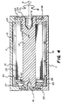
- the flange 33 has a central opening 43 through which the spool core 17 extends to allow rotation of the spool core independently of the flange, and it includes an annular lip or skirt 45 which circumferentially extends from the flange. As shown in FIGS. 1 and 4 , the inner disk 29 and the flange's annular lip 45 are spaced from each other a distance that is less than the width W of the filmstrip F for an approximately 270 o arc that is remote from a film egress/ingress passageway 47 to outside the cassette shell 3, to radially confine the film leader 19 to the film roll 15 along that arc in order to substantially prevent clock-springing of the film roll against the respective inner walls 41, 42 of the shell halves 7, 9.
- the inner disk 29 and the flange's annular lip 45 are spaced from each other a distance that is greater than the width W of the filmstrip F for an approximately 90 o arc that is close to the passageway 47, to allow the film leader 19 beginning with its leading end 21 to escape the radial confinement of the flange's annular lip along that arc in order to enter the passageway.
- a functionally similar arrangement is disclosed in commonly assigned U.S. Patent No. 4,832,275, issued May 23, 1989.
- the flange 33 includes an integrally formed resilient cantilever 48 bordered by a pair of longitudinal slits or openings 49 and 50 cut in the flange to interconnect at a common opening 51 to the central opening 43 of the flange. See FIG. 5.
- the cantilever 48 has a free end portion at the common opening 51 which defines a locking pawl 52 that is inherently biased against the periphery of the spool core 17 at a location within the central opening 43, to drop into either one of two identical notches or detents 53 and 54 cut in the periphery of the spool core.
- the locking pawl 52 rests against the periphery of the spool core 17, the cantilever 48 occupies the longitudinal slit 49.
- the locking pawl 52 When the locking pawl 52 is in one of the detents 53, 54, it is removed from the longitudinal slit 49.
- the locking pawl 52 and the detents 53, 54 are complementarily shaped to locking engage the pawl and one of the detents when the spool core 17 is rotated relative to the flange 33 in the unwinding direction U. Once the locking pawl 52 and one of the detents 53, 54 are lockingly engaged, the flange 33 must rotate with the spool core 17 in the unwinding direction.
- the locking pawl 52 and the detents 53, 54 are complementarily shaped to disengage the pawl and one of the detents and force the pawl onto the periphery of the spool core 17 when the spool core is rotated relative to the flange 33 in the winding direction W.
- Another type of flange to spool core engagement arrangement is disclosed in commonly assigned U.S. Patent No. 5,031,852, issued July 16, 1991.
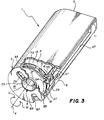
- a control shaft 55 has an integrally formed light valve 57, film stripper 59 and spool lock 61. See FIGS. 1-4.
- the stripper 59 comprises the free end of a resilient cantilever 63 extending from the control shaft 55.
- the control shaft 55 is rotatably supported within the cassette shell 3 by the shell halves 7 and 9. See FIGS. 1-3. Opposite ends 64 and 65 of the control shaft 55 are accessible at the exterior of the cassette shell 3 for engagement to rotate the control shaft.
- the film stripper 59 is in a non-stripping position removed from the film roll 15.
- the stripper 59 is in a stripping position to be received between the leading end 21 of the film leader 19 and the next-inward convolution 23 of the film roll 15 responsive to rotation of the film spool 5 in the unwinding direction U.
- a protruberance 67 may be provided on the underside of the film leader 19 at a location proximate the leading film end 21 to normally lie against the outerside of the next-inward film convolution 23, to maintain a slight space between the leading film end and the next-inward film convolution for receipt of the stripper 59. See FIG. 8.
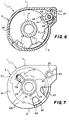
- the spool lock 61 when the control shaft 55 is rotationally oriented with the light valve 57 in its non-blocking position, the spool lock 61 is in a non-locking position removed from the inner disk 29. Conversely, as shown in FIG. 6, when the control shaft 55 is rotationally oriented with the light valve 57 in its light blocking position, the spool lock 61 is in a locking position protruding into any one of four notches or detents 69, 71, 73 and 75 cut in the periphery of the inner disk 29, to prevent substantial rotation of the film spool 5 in the unwinding and winding directions U and W.
- the film spool 5 When the spool lock 61 protrudes into the detent 71, the film spool 5 is rotationally arrested with the exposure status indicator 77 only partly filling the window 79 to visibly indicate the filmstrip F is partly exposed. See FIGS. 9 and 10. Moreover, the beveled edge portion 83 is only present at the window 85. A cut-out edge portion 91 of the outer disk 27 is present at the window 87. See FIG. 10. Consequently, the cassette load prevention mechanism would be disabled at the window 87 but not at the window 85. This permits the film cassette 1 to be used with two different types of cameras, one that can receive the film cassette with the filmstrip F either partly exposed or unexposed and the other that can receive the film cassette only with the filmstrip unexposed.
- the film spool 5 When the spool lock 61 protrudes into the detent 73, the film spool 5 is rotationally arrested with the exposure status indicator 77 completely removed from the window 79 to visibly indicate the filmstrip F is fully exposed. See FIGS. 11 and 12. Moreover, the cut-out edge portion 91 is present at the windows 85 and 87. See FIG. 12. Consequently, the cassette load prevention mechanism would be disabled at the windows 85 and 87. This is in order to prevent any type camera from receiving the film cassette 1 with the filmstrip F fully exposed. When the spool lock 61 protrudes into the detent 75, the film spool 5 is rotationally arrested with the exposure status indicator 77 completely removed from the window 79.
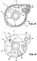
- FIGS. 13 and 14 another indicator, not shown, may be provided on the outer disk 27 to be present at the window 79 to visibly indicate the filmstrip F has been processed to develop any latent images. See FIGS. 13 and 14. Moreover, the cut-out edge portion 91 is present at the window 85 and the beveled edge portion 83 is present at the window 87. See FIG. 14. Consequently, the cassette load prevention mechanism would be disabled at the window 85 but not the window 87. This is in order to allow the film cassette 1 only to be received in apparatus other than a camera, such as an image display device, which would make use of the filmstrip F when it is processed.
- control shaft 55 must be rotated to move the light valve 57 from its light blocking position to its non-blocking position, to move the spool lock 61 from its locking position to its non-locking position, and to move the film stripper 59 from its non-stripping position to its stripping position. See FIGS. 6 and 7.
- the spool core 17 is rotated relative to the flange 33 in the unwinding direction U until the two pieces are lockingly engaged by means of the locking pawl 52 and one of the detents 53, 54. See FIG. 5.
- Continued rotation of the spool core 17 in the same direction will similarly rotate the flange 33 to allow successive longitudinally sections of the filmstrip F beginning with its leading end 21 to exit from between the flange's annular lip 45 and the inner disc 29 along the 90 o arc close to the film egress/ingress passageway 47 where the lip and the disc are spaced from each other a distance that is greater than the width W of the filmstrip F.
- the film stripper 59 will direct successive longitudinal sections of the filmstrip F beginning with its leading end 21 into the passageway 47 for advancement outside the cassette shell 3.
Landscapes
- Physics & Mathematics (AREA)
- General Physics & Mathematics (AREA)
- Details Of Cameras Including Film Mechanisms (AREA)
- Structure And Mechanism Of Cameras (AREA)
Applications Claiming Priority (2)
| Application Number | Priority Date | Filing Date | Title |
|---|---|---|---|
| US787802 | 1991-11-04 | ||
| US07/787,802 US5248108A (en) | 1991-11-04 | 1991-11-04 | Film cassette with unitary film stripper and light blocking device |
Publications (1)
| Publication Number | Publication Date |
|---|---|
| EP0542001A1 true EP0542001A1 (de) | 1993-05-19 |
Family
ID=25142547
Family Applications (1)
| Application Number | Title | Priority Date | Filing Date |
|---|---|---|---|
| EP92117976A Withdrawn EP0542001A1 (de) | 1991-11-04 | 1992-10-21 | Filmkassette mit einer einteiligen Film-Abstreifvorrichtung und einer Lichtdichtung |
Country Status (3)
| Country | Link |
|---|---|
| US (1) | US5248108A (de) |
| EP (1) | EP0542001A1 (de) |
| JP (1) | JPH05224351A (de) |
Families Citing this family (17)
| Publication number | Priority date | Publication date | Assignee | Title |
|---|---|---|---|---|
| JPH06186675A (ja) * | 1992-12-16 | 1994-07-08 | Fuji Photo Film Co Ltd | レンズ付きフイルムユニット |
| JP2801131B2 (ja) * | 1993-09-20 | 1998-09-21 | キヤノン株式会社 | カメラ及びフィルムカートリッジ装填装置 |
| US5500705A (en) * | 1995-01-09 | 1996-03-19 | Eastman Kodak Company | Apparatus and method for securing a thrust film cartridge |
| US5724622A (en) * | 1995-12-22 | 1998-03-03 | Eastman Kodak Company | Film metering mechanism |
| US5694630A (en) * | 1995-12-22 | 1997-12-02 | Eastman Kodak Company | Compact shutter release/film drive |
| US5737656A (en) * | 1995-12-22 | 1998-04-07 | Eastman Kodak Company | Pump camera |
| US5701536A (en) * | 1995-12-22 | 1997-12-23 | Eastman Kodak Company | Camera with film metering responsive shutter release |
| US5765066A (en) * | 1995-12-22 | 1998-06-09 | Eastman Kodak Company | Film advance in a pump camera |
| US5678109A (en) * | 1996-02-16 | 1997-10-14 | Eastman Kodak Company | Camera interior light lock |
| US5666575A (en) * | 1996-02-28 | 1997-09-09 | Eastman Kodak Company | Cartridge status indicator |
| JPH09254479A (ja) * | 1996-03-22 | 1997-09-30 | Sony Corp | プリンタのインクリボンカセット筐体 |
| JPH1039398A (ja) * | 1996-04-19 | 1998-02-13 | Eastman Kodak Co | カメラ |
| JP3614974B2 (ja) * | 1996-04-24 | 2005-01-26 | 富士写真フイルム株式会社 | 写真フイルムの巻込み方法及び装置 |
| FR2756062B1 (fr) * | 1996-11-15 | 1999-02-05 | Kodak Pathe | Structure en u etanche a la lumiere |
| US6802276B2 (en) * | 2001-06-19 | 2004-10-12 | Yazaki Corporation | Meter apparatus and a character plate thereof |
| US9908737B2 (en) * | 2011-10-07 | 2018-03-06 | Perfectvision Manufacturing, Inc. | Cable reel and reel carrying caddy |
| US11407609B1 (en) * | 2021-09-17 | 2022-08-09 | Robert Haag | Wire spool cover |
Citations (5)
| Publication number | Priority date | Publication date | Assignee | Title |
|---|---|---|---|---|
| US4938429A (en) * | 1989-01-12 | 1990-07-03 | Eastman Kodak Co. | Film cassette |
| EP0379797A2 (de) * | 1989-01-26 | 1990-08-01 | Kowa Company Ltd. | Filmmagazin |
| US4974787A (en) * | 1985-04-05 | 1990-12-04 | Asahi Kogaku Kogyo Kabushiki Kaisha | Film guide device |
| EP0426159A2 (de) * | 1989-11-02 | 1991-05-08 | Fuji Photo Film Co., Ltd. | Selbstvorrückende Filmkassette |
| EP0436774A2 (de) * | 1990-01-12 | 1991-07-17 | Eastman Kodak Company | Filmkassette |
Family Cites Families (9)
| Publication number | Priority date | Publication date | Assignee | Title |
|---|---|---|---|---|
| DE410071C (de) * | 1923-10-13 | 1925-02-21 | Zeiss Carl Fa | Zusatzsystem fuer Mikroskopobjektive |
| JPH01231045A (ja) * | 1988-03-11 | 1989-09-14 | Fuji Photo Film Co Ltd | 写真フイルムパトローネ |
| US4832275A (en) * | 1988-05-19 | 1989-05-23 | Eastman Kodak Company | Film cassette |
| US5083721A (en) * | 1989-01-31 | 1992-01-28 | Fuji Photo Film Co., Ltd | Photographic film cartridge |
| JPH02271333A (ja) * | 1989-04-12 | 1990-11-06 | Minolta Camera Co Ltd | フィルム巻き上げ機構 |
| US5047794A (en) * | 1990-07-31 | 1991-09-10 | Eastman Kodak Company | Film cassette with lock-out means for preventing load of exposed film |
| US5049913A (en) * | 1990-07-31 | 1991-09-17 | Eastman Kodak Company | Film cassette with locking means for exposure status indicator |
| US5032861A (en) * | 1990-10-15 | 1991-07-16 | Eastman Kodak Company | Film cassette with lock-out means for preventing load of exposed film |
| US5083720A (en) * | 1991-04-03 | 1992-01-28 | Eastman Kodak Company | Film cassette with cooperating stripper and light-lock |
-
1991
- 1991-11-04 US US07/787,802 patent/US5248108A/en not_active Expired - Fee Related
-
1992
- 1992-10-21 EP EP92117976A patent/EP0542001A1/de not_active Withdrawn
- 1992-11-04 JP JP4295260A patent/JPH05224351A/ja active Pending
Patent Citations (5)
| Publication number | Priority date | Publication date | Assignee | Title |
|---|---|---|---|---|
| US4974787A (en) * | 1985-04-05 | 1990-12-04 | Asahi Kogaku Kogyo Kabushiki Kaisha | Film guide device |
| US4938429A (en) * | 1989-01-12 | 1990-07-03 | Eastman Kodak Co. | Film cassette |
| EP0379797A2 (de) * | 1989-01-26 | 1990-08-01 | Kowa Company Ltd. | Filmmagazin |
| EP0426159A2 (de) * | 1989-11-02 | 1991-05-08 | Fuji Photo Film Co., Ltd. | Selbstvorrückende Filmkassette |
| EP0436774A2 (de) * | 1990-01-12 | 1991-07-17 | Eastman Kodak Company | Filmkassette |
Also Published As
| Publication number | Publication date |
|---|---|
| JPH05224351A (ja) | 1993-09-03 |
| US5248108A (en) | 1993-09-28 |
Similar Documents
| Publication | Publication Date | Title |
|---|---|---|
| EP0540938B1 (de) | Filmpatrone mit einem integrierten, lichtblockierenden und spuleblockierenden Teil | |
| US5248108A (en) | Film cassette with unitary film stripper and light blocking device | |
| US5231438A (en) | Camera with interlock for cover piece and cartridge light shield | |
| US4887110A (en) | Film cassette | |
| EP0427922B1 (de) | Kameravorrichtung zur Ladeblockierung eines belichteten Films | |
| US5032861A (en) | Film cassette with lock-out means for preventing load of exposed film | |
| US4908641A (en) | Photographic film and film cassette | |
| US5215273A (en) | Film unwinding apparatus | |
| US5049912A (en) | Film cassette with locking means for exposure status indicator | |
| US4883236A (en) | Film cassette | |
| US4987437A (en) | Film cassette with film exposure status indicator | |
| EP0397083B1 (de) | Messunterdrückungsmechanismus | |
| EP0480291B1 (de) | Zur Verwendung mit einer Filmkassette bestimmte Kamera mit Verriegelungseinrichtung für Belichtungszustandsindikator | |
| EP0540937B1 (de) | Filmpatrone inklusive Filmspule mit Endflanschen | |
| US5295634A (en) | Film cassette with spool core having fastening hook | |
| US5048770A (en) | Film cassette with exposure status indicator | |
| US5522563A (en) | Film cassette with latching device to prevent separation of cassette halves | |
| US5270760A (en) | Film cassette with internal film drive | |
| US5153627A (en) | Film cassette with spool lock | |
| EP0461527B1 (de) | Filmkassette mit einer Anzeige für den Belichtungszustand | |
| US5065952A (en) | Film cassette with film exposure status indicator | |
| US5111229A (en) | Film cassette with tri-lobe spool | |
| US5473398A (en) | Opened light-shielding door of film cassette overlaps extension of film gate device to bridge a gap between the cassette and gate device |
Legal Events
| Date | Code | Title | Description |
|---|---|---|---|
| PUAI | Public reference made under article 153(3) epc to a published international application that has entered the european phase |
Free format text: ORIGINAL CODE: 0009012 |
|
| AK | Designated contracting states |
Kind code of ref document: A1 Designated state(s): BE CH DE ES FR GB IT LI NL |
|
| 17P | Request for examination filed |
Effective date: 19931022 |
|
| 17Q | First examination report despatched |
Effective date: 19950308 |
|
| STAA | Information on the status of an ep patent application or granted ep patent |
Free format text: STATUS: THE APPLICATION HAS BEEN WITHDRAWN |
|
| 18W | Application withdrawn |
Withdrawal date: 19950415 |