EP0542015A1 - Procédé et dispositif pour le creusement d'un plant avec une pelleteuse - Google Patents
Procédé et dispositif pour le creusement d'un plant avec une pelleteuse Download PDFInfo
- Publication number
- EP0542015A1 EP0542015A1 EP92118224A EP92118224A EP0542015A1 EP 0542015 A1 EP0542015 A1 EP 0542015A1 EP 92118224 A EP92118224 A EP 92118224A EP 92118224 A EP92118224 A EP 92118224A EP 0542015 A1 EP0542015 A1 EP 0542015A1
- Authority
- EP
- European Patent Office
- Prior art keywords
- spoon
- laser receiver
- line
- laser
- signal
- Prior art date
- Legal status (The legal status is an assumption and is not a legal conclusion. Google has not performed a legal analysis and makes no representation as to the accuracy of the status listed.)
- Withdrawn
Links
- 238000000034 method Methods 0.000 title claims abstract description 11
- 238000011156 evaluation Methods 0.000 claims description 23
- 238000012937 correction Methods 0.000 claims description 21
- 230000015572 biosynthetic process Effects 0.000 claims description 12
- SEQDDYPDSLOBDC-UHFFFAOYSA-N Temazepam Chemical compound N=1C(O)C(=O)N(C)C2=CC=C(Cl)C=C2C=1C1=CC=CC=C1 SEQDDYPDSLOBDC-UHFFFAOYSA-N 0.000 claims description 4
- 238000004519 manufacturing process Methods 0.000 claims description 4
- 238000004804 winding Methods 0.000 description 26
- 238000010586 diagram Methods 0.000 description 3
- 208000037516 chromosome inversion disease Diseases 0.000 description 2
- 230000001960 triggered effect Effects 0.000 description 2
- 230000004913 activation Effects 0.000 description 1
- 238000010276 construction Methods 0.000 description 1
- 238000009415 formwork Methods 0.000 description 1
- 238000005259 measurement Methods 0.000 description 1
- 230000015654 memory Effects 0.000 description 1
- 238000003825 pressing Methods 0.000 description 1
Images



Classifications
-
- E—FIXED CONSTRUCTIONS
- E02—HYDRAULIC ENGINEERING; FOUNDATIONS; SOIL SHIFTING
- E02F—DREDGING; SOIL-SHIFTING
- E02F3/00—Dredgers; Soil-shifting machines
- E02F3/04—Dredgers; Soil-shifting machines mechanically-driven
- E02F3/28—Dredgers; Soil-shifting machines mechanically-driven with digging tools mounted on a dipper- or bucket-arm, i.e. there is either one arm or a pair of arms, e.g. dippers, buckets
- E02F3/36—Component parts
- E02F3/42—Drives for dippers, buckets, dipper-arms or bucket-arms
- E02F3/43—Control of dipper or bucket position; Control of sequence of drive operations
- E02F3/435—Control of dipper or bucket position; Control of sequence of drive operations for dipper-arms, backhoes or the like
- E02F3/437—Control of dipper or bucket position; Control of sequence of drive operations for dipper-arms, backhoes or the like providing automatic sequences of movements, e.g. linear excavation, keeping dipper angle constant
Definitions
- the invention relates to a method for producing a formation relative to a rectilinear, rotating, stationary light, in particular laser beam with a backhoe, which has drive units for its main boom and a light, in particular laser receiver, and a device for carrying out the method.
- a laser transmitter is set up on the site, which emits a straight laser beam as a reference line.
- a laser receiver aligned with the laser beam level is firmly attached to the arm of the backhoe and informs the excavator operator of the position of the arm relative to the reference plane.
- the height of the bucket with respect to the reference plane defined by the laser beam must be checked visually by the excavator operator and corrective interventions must be carried out manually by him. It is particularly disadvantageous that a vertical position of the receiver is not possible during the pulling-off process, which results in an uncompensable height error and a corresponding inaccuracy of the formation. Furthermore, height corrections have to be carried out by the excavator operator via the actuation of the lifting cylinder, while at the same time by actuating the dipper arm cylinder to create the Planum material is removed. Therefore, a measurement of the formation proves to be inevitable, which is time-consuming.
- the invention has for its object to facilitate the work of the excavator operator in the manufacture of a plenum.
- a predetermined height position of the spoon with respect to the laser beam is kept constant by means of the laser receiver influencing the drive units during stick movements. This leaves the excavator operator free of manual correction movements for bucket height during stick movements. There is also no need for another person to measure the formation. Formwork material is therefore no longer required in trench construction because it is no longer necessary to stay on the bottom of the trench.
- the output signals of the laser receiver are converted into correction signals for the drive units of the bucket excavator.
- a predetermined position of the bucket is kept constant during the stick movements by means of an electronic pendulum, the excavator operator is also freed from manual correction movements of the bucket during stick movements.
- a device for producing a formation can be used relative to a rectilinear rotating, stationary light, in particular laser beam with a backhoe, which has drive units for its main boom and a light, in particular laser receiver.
- an evaluation device is connected to the laser receiver, which generates correction signals from the output signals of the laser receiver, which represent the deviation of the bucket from the predetermined height and control a proportional valve connected downstream of the evaluation device, which is connected in parallel with the pilot device of the backhoe.
- the evaluation device takes up little space, so that it can be accommodated in the driver's cab.
- the hydraulic system of the excavator only needs to be supplemented with the proportional valve, so that conventional backhoe excavators only need to be retrofitted with the two components mentioned.
- the laser receiver is expediently attached to the spoon in a height-adjustable manner. It proves to be particularly advantageous if the laser receiver has a plurality of receiving surfaces for the laser beam, which are arranged in an essentially vertical row. With this measure, the movement of the spoon into the specified target position is accelerated after deviations therefrom, because stronger correction signals can be generated from the specified target position in the event of greater deviations.
- the evaluation device advantageously comprises an evaluation electronics connected to the laser receiver as well as an amplifier connected downstream of the latter Proportional valve controls.
- An embodiment of the invention is helpful for the excavator operator, which provides a display which, depending on the output signals of the laser receiver, generates signals which are perceptible to the excavator operator and which represent the deviations from the predetermined altitude.
- the display can expediently be a luminaire field which is controlled by the evaluation electronics.
- the evaluation electronics can have a logic unit which receives the output signals of the laser receiver and which controls the display. It is particularly expedient if the evaluation electronics generate an output signal for the amplifier from the output signals of the laser receiver, the amplitude and / or polarity of which represent the deviation from the predetermined altitude.
- the device according to the invention can preferably be designed in a user-friendly manner in that an electronic pendulum influencing the spoon cylinder is attached to the spoon.
- the electronic pendulum can then control a further proportional valve, which is connected in parallel to the pilot device for the spoon cylinder.
- the electronic pendulum attached to the spoon and the laser receiver are expediently combined to form an assembly attached to the spoon.
- the backhoe shown schematically in Figure 1 has a boom 1 in a known manner, which in a plane perpendicular to the base 6, on which the formation is to be created, around a hinge pin, not shown, provided on the chassis of the backhoe excavator by means of a on the chassis of the backhoe and on the underside of the boom 1 attacking lifting cylinder 2 can be pivoted.
- a stick 10 is articulated at 12, which can be pivoted in the said vertical plane by means of a stick cylinder 4 articulated on the boom 1 and acting on the head of the stick.
- a spoon 20 is articulated by means of a schematically illustrated pivot pin 14.
- the spoon 20 can be pivoted in the vertical plane by means of a spoon cylinder 25 articulated on the stick 10, which on a from the spoon 20 protruding eye 21 hinges.
- the spoon 20 is shown in the pull-off position, in which the pull-off edge 24 contacts the base 6.
- the spoon 20 has a sectionally flat upper side 22, which extends essentially parallel to the base 6 in the pull-off position shown.
- an inclinometer or electronic pendulum 30 is attached, which can be of a commercially available type.
- the laser receiver 50 is adjustable relative to the inclinometer 30 and thus to the spoon 20 along the receiver holder 40 in height above the base 6.
- the receiving surface of the laser receiver 50 for receiving laser beams is located on the front side 53 of the laser receiver 50 facing away from the receiver holder 40.
- a laser emitter not shown, is set up in the vicinity thereof, the transmitter of which emits laser light in a plane 5 (FIG. 6) which is essentially parallel to the base 6 and rotates about a substantially vertical axis at a constant frequency.
- the laser transmitter is set up in such a way that the laser light emitted in plane 5 strikes the receiving surfaces to be explained within a window 51 (FIG. 3) on the front side 53 of the laser receiver 50.
- the window 51 shown schematically on the left in FIG. 3 has four receiving surfaces 52, 54, 56, 58 for laser light, which are arranged next to one another in a vertical row and are shown schematically here as squares. If the laser light incident in the window 51 hits the two inner receiving surfaces 54, 56, the spoon 20 is in its desired position with respect to the plane 5, in which the level can be produced. If the laser beam hits the uppermost receiving surface 52, the spoon 20 is too low and must be raised. If the laser light hits the lowermost receiving surface 58, the spoon 20 is too high with respect to the formation to be produced and must be lowered.
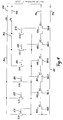
- An electronic evaluation circuit is used to form the correction signals required for the eventual raising or lowering of the spoon.
- An output signal line 80 leads from the receiving surface 52 via an amplifier 81 to a monostable multivibrator 82.
- the output line 83 of the monostable multivibrator 82 leads to a first input of an AND gate 86, the output line 88 of which leads to the input of a driver circuit 120, which connects a relay connected downstream winding 121 can supply with current.
- a branch line 84 from the output line 83 leads to an input of an AND gate 85.
- An output signal line 90 from the receiver surface 54 leads via an amplifier 91 to a monostable multivibrator 92, whose output line 93 leads to a first input of an AND gate 96 and from which a first branch line 94 to the second input of an AND gate 85, a second Branch 98 to one Input of an AND gate 95, a third branch line 66 via an inverting stage to the second input of the AND gate 86 and a fourth branch line 68 via an inverting stage to an input of an AND gate 106.
- the output line 89 of the AND gate 85 leads to an input of an OR gate 87 and to a second input of an OR gate 97.
- a second input of the OR gate 87 is the output line 88, which at the same time is a third input for the OR Gate 97 is.
- the output signal line 100 of the receiving surface 56 leads via an amplifier 101 to a monostable multivibrator 102 whose output line 103 leads to a first input of an AND gate 106 and from which a branch line 108 to the second input of the AND gate 95, a branch line 67 an inversion stage to AND gate 96, another branch line 108 leads to an input of an AND gate 105, and finally another branch line 69 leads to an AND gate 116 via an inversion stage.
- the output line 118 of the AND gate 106 leads to an input of an OR gate 107.
- An output signal line 110 from the receiving surface 58 leads via an amplifier 111 to a monostable multivibrator 112, whose output signal line 113 leads to a second input of the AND gate 116.
- a branch line 119 of the output signal line 113 is connected to a second input of an AND gate 105.
- the output line 115 of the AND gate 105 leads to a second input of the OR gate 107 and to an input of the OR gate 117.
- the output line 119 leads on the one hand to a driver stage 130 and on the other hand via branch lines to another Input of the OR gate 107 and to a further input of the OR gate 117.
- the output line of the OR gate 87 leads to a driver unit 122 which can supply a relay winding 123 with current.
- the output line of the OR gate 97 leads to a driver circuit 124 which can supply a downstream relay winding 123 with current.
- An output line of the OR gate 107 leads to a driver circuit 126 which can supply a downstream relay winding 127 with current.
- An output line of the OR gate 117 leads to a driver circuit 128 which can supply a downstream relay winding 129 with current.
- the driver circuit 130 serves to supply power to a downstream relay winding 131.
- the output line 114 of the AND gate 95 leads via a driver circuit 135 for a downstream indicator light 136.
- This part of the evaluation circuit works as follows: If a laser light pulse falls on the receiving surface 52, this means that the spoon 20 is too low for the desired level. Such a laser light pulse appears as an electrical pulse LC on the line 80 and triggers the flip-flop 82.
- the flip-flops 82, 92, 102 and 112 are designed so that each of them retains its triggered state for a period of, for example, 100 ms after triggering shortly before the next laser light pulse following the triggering arrives on one of the receiving surfaces 52, 54, 56, 58.
- After triggering of the flip-flop 82 there is therefore a signal on line 83, which the driver circuit 120 and via the OR gate 87, the driver circuit 122 and the OR gate 97 activates the driver circuit 124.
- the spoon 20 is still too low with respect to the desired planum, but its position does not have to be corrected as much.
- the flip-flops 82 and 92 are triggered with the result that there is a signal on each of the lines 83 and 93, which activates the driver circuits 122 and 124 via AND gates 85 and OR gates 87 and 97, whereas the driver circuit 120 is not switched on due to the lack of an output signal on line 88.
- the LF signal on line 90 with the RF signal occurring on line 100 is processed by AND gate 95 to form a trigger signal on line 114 for driver stage 135.
- the green indicator light 136 lights up.
- the RF signal on line 100 is combined with the HC signal appearing on line 110 by the AND gate 105 and the driver circuits 126 and 128 are via the OR gates 107 and 117 activated so that the relay windings 127 and 129 carry current.
- the HC signal on line 110 causes the driver circuits 126, 128 and 130 to be activated and the relay windings 127, 129, 131 to carry current.
- the part of the evaluation electronics shown in FIG. 4 first has a line 140 which receives a voltage source of -9V during operation via connection 148.
- the line 140 is connected via a resistor R38 to a line 141 which, in operation, is at a reference potential of, for example, 0 V (connection 146).
- a resistor R39 lies in parallel with the resistor R38 between the line 140 and the line 141.
- Another parallel resistor R40 also lies between the line 140 and the line 141.
- line 142 receives a voltage of + 9V from terminal 149 and is connected to line 141 via three resistors R41, R42 and R43 connected in parallel.
- each of resistors R38 ... R43 is a potentiometer with a fixed tap A38 -A43.
- a series of six switches K1 ... K6 are provided, which are connected as follows: The normally open contact AK3 of the switch K3 is connected to the tap A38.
- the Normally open contact AK2 of the switch K2 is connected to the tap A39.
- the normally open contact AK1 of the changeover switch K1 is connected to the tap A40.
- the make contact AK4 of the switch K4 is connected to the tap A41.
- the make contact AK5 of the changeover switch K5 is connected to the tap A42, and the make contact AK6 of the changeover switch K6 is connected to the tap A43.
- the normally closed contact RK3 of the switch K3 is connected to line 141.
- the normally closed contact RK2 of the switch K2 is connected to the switching arm of the switch K3.
- the normally closed contact RK1 of the switch K1 is connected to the switching arm of the switch K2.
- the normally closed contact RK4 of the switch K4 is connected to the switching arm of the switch K1.
- the normally closed contact RK5 of the changeover switch K5 is connected to the changeover switch K4 and the normally closed contact RK6 of the changeover switch K6 is connected to the switching arm of the changeover switch K5.
- the switching arm of the switch K6 is connected to an output connection 144.
- the relay winding 121 is assigned the changeover switch K1
- the relay winding 123 is assigned the changeover switch K2
- the relay winding 125 is assigned the changeover switch K3
- the relay winding 127 is assigned the changeover switch K4
- the relay winding 129 is assigned the changeover switch K5
- the relay winding 131 is that Switch K6 assigned.
- Corresponding connections of a Rexroth amplifier VT3024 are connected to the output connection 144 and the connection 146 of the line 141, the connection 148 of the line 140 and the connection 149 of the line 142.
- This amplifier supplies the voltages of -9V and + 9V for lines 140 and 142 as well as the reference potential for line 141 and processes the output signal occurring at output 144 according to polarity and amplitude.
- the coding is expediently chosen so that for a large positional deviation of the spoon 20 downwards, i.e. when the signal LC occurs, a higher partial voltage is tapped at the resistor R40 than when the positional deviation of the spoon 20 is lower, that is to say when the signal LF occurs alone.
- the positive partial voltage amplitude tapped off at the resistor R43 is selected to be larger than if the positional deviation of the spoon 20 is only upwards, if the signal HF occurs.
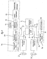
- FIG. 5 shows the basic signal flow from laser receiver 50 to evaluation electronics 70 (FIGS. 3 and 4).
- a display 72 which is controlled by the evaluation electronics, is located on the dashboard of the excavator operator.
- This display panel 72 comprises a total of 7 indicator lights, specifically the red illuminated indicator lights 71, 73, 75 and 77, 79 and 132 and the green illuminated indicator light 136.
- the indicator light 71 is connected in parallel with the relay winding 121 and receives this from the driver circuit 120 current.
- the Indicator light 73 is the relay winding 123 and the indicator light 75 is connected in parallel to the relay winding 125.
- the indicator lights 77 of the relay winding 127, the indicator light 79 of the relay winding 129 and the indicator light 132 of the relay winding 131 are connected in parallel.
- the signal LC strong positional deviation downwards
- the indicator lights 71, 73, 75 light up, with medium positional deviation downwards (signals LC and LF) only the indicator lights 73 and 75 light up and with a small positional deviation downwards (signal LF alone ) only the signal lamp 75 lights up.
- the signal lights 77, 79, 132 light up when there is a large position deviation
- the signal lights 77 and 79 light up when the position is medium (HF and HC signals)
- the signal light 77 illuminates upwards when the position is slight (HF signal alone).
- the green signal lamp 136 lights up, the spoon 20 is in the desired position.
- the evaluation electronics 70 outputs a coded output signal to the amplifier 74 at the connection 144, which discriminates the output signal according to amplitude and polarity and outputs an output control signal representative of the coded output signal to a proportional valve 76 for the lifting cylinder 2.
- the backhoe has a control oil unit 7 in a manner known per se, which supplies control oil to a pilot control device 9 via a pressure line 8.
- the pilot control device 9 has in the usual way an operating lever, not shown, for the lifting cylinder 2 and the spoon cylinder 25. The control for the stick cylinder 4 is not shown.
- a pressure line 11 branches off from the pressure medium line 8 and leads to the proportional valve 76 mentioned.
- the proportional valve 76 Under control of the output control signal emitted by the amplifier 74, the proportional valve 76 emits a correction control signal on line 13, which into the one serving for the actuation of the lifting cylinder 2 from Pilot control device 9 coming control line 15 opens.
- the proportional valve 76 is thus connected in parallel to the lifting cylinder section in the pilot control device 9 and serves as a correction element for the height correction of the spoon 20.
- a further proportional valve 26 is connected in parallel with the part of the pilot control device 9 relating to the spoon cylinder.
- the proportional valve 26 receives control oil via a further branch line 16 from the pressure medium line 8.
- the inclinometer 30 generates an actuating signal for the proportional valve 26 on an output line 32, the actuating signal 32 indicating the deviation of the top 22 of the spoon from the horizontal or from one to the bottom 6 parallel plane is proportional.
- the control signal received via line 32 converts the proportional valve into an oil correction signal, which feeds the correction signal via line 17 into an output line 18 from pilot control device 9.
- the output line 18 supplies the spoon cylinder 25 with control oil.
- the bucket 20 initially remains in the defined position shown in FIG. 6 relative to the reference plane specified by the laser beam 5, specifically because of the control circuit comprising the inclinometer 30 and the proportional valve 26.
- the spoon 20 now occupies a position that is too high relative to the planum 6 to be produced, so that corresponding laser light impulses (first on the receiver surface 56 and then) strike the receiver surface 58, that is to say the signal HC is generated.
- a correction signal for the lifting cylinder 2 is generated as described, with the result that the lifting cylinder 2 lowers the deflector 1 by the height error A1 (FIG. 6), that is, the bucket cylinder 25 assumes its target position, which the excavator operator is informed by the green indicator light 129 lighting up becomes.
- the excavator operator does not have to operate the control element on the pilot control device 9 to correct the height error A1.
- the handle 10 with the spoon 20 assumes the position shown on the left in FIG. 6, in which the spoon 20 assumes the predetermined target position.
- the bucket 20 When pivoting the arm 10 in the counterclockwise direction, the bucket 20 initially remains in its desired position due to the control circuit mentioned with inclinometer 30 and proportional valve 26. The height deviation of the bucket 20 is now smaller with A2, the bucket 20 is too high with respect to the formation that is to be produced . Laser light pulses therefore fall on the receiving surface 56 and generate the signal HF. As described, this causes the generation of a correction signal by the proportional valve 76 for the lifting cylinder 2, which is increased by the height difference A2 is lowered. After completing the correction, the handle 10 and the spoon 20 then assume the position shown on the right in FIG. 6, in which the spoon 20 is held in the correct position.
- the invention is not restricted to the type of correction signal acquisition for the lifting cylinder described above.
- the specified gates can be replaced by programmable memories.
- the indicator lights can be dispensed with, so that the signals LC, LF, HF and HC and their combinations can be implemented directly to form a coded output signal which can be used by the amplifier 74.
- the indicator lights 71, 73, 75, 136, 77, 79, 132 can be housed in a separate box in the operator's field of vision in the driver's cab, so that the operator can be sure that arm movements that are carried out when the lamp 136 lights up, result in the desired, absolutely level formation.
Landscapes
- Engineering & Computer Science (AREA)
- Mining & Mineral Resources (AREA)
- Mechanical Engineering (AREA)
- Life Sciences & Earth Sciences (AREA)
- General Life Sciences & Earth Sciences (AREA)
- Paleontology (AREA)
- Civil Engineering (AREA)
- General Engineering & Computer Science (AREA)
- Structural Engineering (AREA)
- Operation Control Of Excavators (AREA)
- Component Parts Of Construction Machinery (AREA)
Applications Claiming Priority (4)
| Application Number | Priority Date | Filing Date | Title |
|---|---|---|---|
| DE4137067 | 1991-11-11 | ||
| DE4137067 | 1991-11-11 | ||
| DE19924211388 DE4211388A1 (de) | 1991-11-11 | 1992-04-04 | Verfahren und vorrichtung zur herstellung eines planums mittels eines loeffelbaggers |
| DE4211388 | 1992-04-04 |
Publications (1)
| Publication Number | Publication Date |
|---|---|
| EP0542015A1 true EP0542015A1 (fr) | 1993-05-19 |
Family
ID=25908999
Family Applications (1)
| Application Number | Title | Priority Date | Filing Date |
|---|---|---|---|
| EP92118224A Withdrawn EP0542015A1 (fr) | 1991-11-11 | 1992-10-24 | Procédé et dispositif pour le creusement d'un plant avec une pelleteuse |
Country Status (2)
| Country | Link |
|---|---|
| EP (1) | EP0542015A1 (fr) |
| DE (1) | DE4211388A1 (fr) |
Cited By (2)
| Publication number | Priority date | Publication date | Assignee | Title |
|---|---|---|---|---|
| US6108076A (en) * | 1998-12-21 | 2000-08-22 | Trimble Navigation Limited | Method and apparatus for accurately positioning a tool on a mobile machine using on-board laser and positioning system |
| US6253160B1 (en) | 1999-01-15 | 2001-06-26 | Trimble Navigation Ltd. | Method and apparatus for calibrating a tool positioning mechanism on a mobile machine |
Families Citing this family (2)
| Publication number | Priority date | Publication date | Assignee | Title |
|---|---|---|---|---|
| DE4324478A1 (de) * | 1993-07-21 | 1995-01-26 | Ralf Dr Hinkel | Rotationslaser mit verbesserter Sichtbarkeit |
| DE19800121A1 (de) * | 1998-01-03 | 1999-07-15 | Norbert Dahlig | Bagger |
Citations (3)
| Publication number | Priority date | Publication date | Assignee | Title |
|---|---|---|---|---|
| JPS56105030A (en) * | 1980-01-22 | 1981-08-21 | Komatsu Ltd | Automatic controller for working machine |
| EP0288314A1 (fr) * | 1987-04-24 | 1988-10-26 | Laser Alignment, Inc. | Dispositif et méthode pour la commande d'un excavateur hydraulique |
| EP0369694A2 (fr) * | 1988-11-14 | 1990-05-23 | Spectra Precision, Inc. | Dispositif muni d'un laser pour régler la profondeur d'un engin de terrassement |
Family Cites Families (2)
| Publication number | Priority date | Publication date | Assignee | Title |
|---|---|---|---|---|
| JPS54150802A (en) * | 1978-05-16 | 1979-11-27 | Komatsu Mfg Co Ltd | Blade automatic controller of bulldozer and its method |
| SE436436B (sv) * | 1981-06-18 | 1984-12-10 | Eurotrade Machine Pool Ab | Djupmetare vid grevmaskiner |
-
1992
- 1992-04-04 DE DE19924211388 patent/DE4211388A1/de not_active Ceased
- 1992-10-24 EP EP92118224A patent/EP0542015A1/fr not_active Withdrawn
Patent Citations (3)
| Publication number | Priority date | Publication date | Assignee | Title |
|---|---|---|---|---|
| JPS56105030A (en) * | 1980-01-22 | 1981-08-21 | Komatsu Ltd | Automatic controller for working machine |
| EP0288314A1 (fr) * | 1987-04-24 | 1988-10-26 | Laser Alignment, Inc. | Dispositif et méthode pour la commande d'un excavateur hydraulique |
| EP0369694A2 (fr) * | 1988-11-14 | 1990-05-23 | Spectra Precision, Inc. | Dispositif muni d'un laser pour régler la profondeur d'un engin de terrassement |
Non-Patent Citations (1)
| Title |
|---|
| PATENT ABSTRACTS OF JAPAN vol. 5, no. 183 (M-097)(855) 21. November 1981 & JP-A-56 105 030 ( KOMATSU LTD ) * |
Cited By (2)
| Publication number | Priority date | Publication date | Assignee | Title |
|---|---|---|---|---|
| US6108076A (en) * | 1998-12-21 | 2000-08-22 | Trimble Navigation Limited | Method and apparatus for accurately positioning a tool on a mobile machine using on-board laser and positioning system |
| US6253160B1 (en) | 1999-01-15 | 2001-06-26 | Trimble Navigation Ltd. | Method and apparatus for calibrating a tool positioning mechanism on a mobile machine |
Also Published As
| Publication number | Publication date |
|---|---|
| DE4211388A1 (de) | 1993-05-13 |
Similar Documents
| Publication | Publication Date | Title |
|---|---|---|
| DE102007026527B4 (de) | Steuerungssystem für einen Motor-Grader, Motor-Grader und Verfahren zum Steuern eines Motor-Graders | |
| DE3409851C2 (de) | Gleisstopf-, Nivellier- und Richtmaschine mit einer Einrichtung zur Korrektur der Höhenlage und Querneigung eines Gleises | |
| DE2331915A1 (de) | Verfahren und vorrichtung zum stopfen und nivellieren eines gleises | |
| DE2558236C2 (de) | Verfahren und Einrichtung zur Feststellung des Zustandes bzw. der Dichte von grobkörnigem Gut, insbesondere eines Gleis-Schotterbettes | |
| DE3239588A1 (de) | Einrichtung zum steuern der schar von bodenplaniermaschinen | |
| DE19520166C2 (de) | Maststeuerung für nicht-schwingungsfreie Vielgelenkgeräte, insbesondere für vielgliedrige Betonpumpen-Verteilausleger | |
| DE69513806T2 (de) | Anordnung der steuereinrichtung einer gesteinbohrausrüstung | |
| EP0007009B1 (fr) | Procédé d'affichage de grandeurs de réglage pour la commande d'une machine à imprimer à cylindres rotatifs | |
| DE4211388A1 (de) | Verfahren und vorrichtung zur herstellung eines planums mittels eines loeffelbaggers | |
| DE2057119A1 (de) | Fahrbare Gleisstopf Nivellierma schine | |
| DE112005001879T5 (de) | Steuerungssystem und Steuerungsverfahren für Fluiddruckstellantrieb und Fluiddruck-Maschine | |
| DE9204675U1 (de) | Vorrichtung zur Herstellung eines Planums mittels eines Löffelbaggers | |
| DE2933294A1 (de) | Audiometer | |
| EP4129037B1 (fr) | Machine de travail agricole, ainsi que dispositif de commande | |
| DE2612109A1 (de) | Gleisverdicht- bzw. stopfmaschine | |
| EP0092025A1 (fr) | Tracteur agricole avec dispositif d'attelage d'appareillage arrière et frontal | |
| DE2213056A1 (de) | Steuereinrichtung für Erdhobler | |
| DE29908429U1 (de) | Vorrichtung zum Verstellen des Arbeitsabstandes | |
| DE19942504A1 (de) | Einrichtung zum Wenden eines an einem landwirtschaftlichen Fahrzeug angelenkten Anbaugeräts, insbesondere eines Drehpfluges | |
| DE2737976C2 (de) | Fahrbare Maschine zum Messen und bzw. oder Korrigieren der Gleishöhenlage | |
| DE3334573C2 (de) | Baufahrzeug zum Einbringen und/oder Herausziehen von Pfählen, Spundwänden, Pfahlgründungen o.dgl. in oder aus dem Erdreich oder zum Durchführen von Erdbohrungen | |
| DE1078151B (de) | Einrichtung zum in Gleislaengsrichtung fortschreitenden Anheben eines Gleisabschnittes | |
| DE2925223A1 (de) | Vorrichtung zum ueberwachen der verschiebung einer lichtbogenofen-elektrode | |
| DD209008A5 (de) | Gleisstopfmaschine | |
| DE19544073C2 (de) | Fahrbares Abziehgerät |
Legal Events
| Date | Code | Title | Description |
|---|---|---|---|
| PUAI | Public reference made under article 153(3) epc to a published international application that has entered the european phase |
Free format text: ORIGINAL CODE: 0009012 |
|
| AK | Designated contracting states |
Kind code of ref document: A1 Designated state(s): FR GB IT NL SE |
|
| STAA | Information on the status of an ep patent application or granted ep patent |
Free format text: STATUS: THE APPLICATION IS DEEMED TO BE WITHDRAWN |
|
| 18D | Application deemed to be withdrawn |
Effective date: 19931120 |