EP0542075A2 - Verfahren zum Anschliessen eines elektrischen koaxialen Miniatursteckers und sich daraus ergebender Steckeranschluss - Google Patents
Verfahren zum Anschliessen eines elektrischen koaxialen Miniatursteckers und sich daraus ergebender Steckeranschluss Download PDFInfo
- Publication number
- EP0542075A2 EP0542075A2 EP92118722A EP92118722A EP0542075A2 EP 0542075 A2 EP0542075 A2 EP 0542075A2 EP 92118722 A EP92118722 A EP 92118722A EP 92118722 A EP92118722 A EP 92118722A EP 0542075 A2 EP0542075 A2 EP 0542075A2
- Authority
- EP
- European Patent Office
- Prior art keywords
- shield member
- rear portion
- signal pin
- shield
- insulating jacket
- Prior art date
- Legal status (The legal status is an assumption and is not a legal conclusion. Google has not performed a legal analysis and makes no representation as to the accuracy of the status listed.)
- Granted
Links
- 238000000034 method Methods 0.000 title claims abstract description 14
- 238000005219 brazing Methods 0.000 claims description 5
- 239000007769 metal material Substances 0.000 claims 1
- 239000012212 insulator Substances 0.000 description 30
- 210000003811 finger Anatomy 0.000 description 13
- 238000003466 welding Methods 0.000 description 5
- 108091006146 Channels Proteins 0.000 description 3
- 239000004020 conductor Substances 0.000 description 3
- 238000003780 insertion Methods 0.000 description 3
- 230000037431 insertion Effects 0.000 description 3
- 229910052751 metal Inorganic materials 0.000 description 3
- 239000002184 metal Substances 0.000 description 3
- PXHVJJICTQNCMI-UHFFFAOYSA-N Nickel Chemical compound [Ni] PXHVJJICTQNCMI-UHFFFAOYSA-N 0.000 description 2
- BQCADISMDOOEFD-UHFFFAOYSA-N Silver Chemical compound [Ag] BQCADISMDOOEFD-UHFFFAOYSA-N 0.000 description 2
- 238000002788 crimping Methods 0.000 description 2
- 230000000694 effects Effects 0.000 description 2
- 238000004519 manufacturing process Methods 0.000 description 2
- 239000000463 material Substances 0.000 description 2
- 230000013011 mating Effects 0.000 description 2
- 229910052709 silver Inorganic materials 0.000 description 2
- 239000004332 silver Substances 0.000 description 2
- 229910000679 solder Inorganic materials 0.000 description 2
- 238000005476 soldering Methods 0.000 description 2
- 239000004593 Epoxy Substances 0.000 description 1
- 230000000712 assembly Effects 0.000 description 1
- 238000000429 assembly Methods 0.000 description 1
- 230000005540 biological transmission Effects 0.000 description 1
- 230000015556 catabolic process Effects 0.000 description 1
- 238000000576 coating method Methods 0.000 description 1
- 238000004891 communication Methods 0.000 description 1
- 230000000295 complement effect Effects 0.000 description 1
- 230000006835 compression Effects 0.000 description 1
- 238000007906 compression Methods 0.000 description 1
- 238000010276 construction Methods 0.000 description 1
- 230000007423 decrease Effects 0.000 description 1
- 230000002950 deficient Effects 0.000 description 1
- 238000006731 degradation reaction Methods 0.000 description 1
- 239000003989 dielectric material Substances 0.000 description 1
- 238000006073 displacement reaction Methods 0.000 description 1
- 239000000945 filler Substances 0.000 description 1
- 238000009413 insulation Methods 0.000 description 1
- 238000005304 joining Methods 0.000 description 1
- MYWUZJCMWCOHBA-VIFPVBQESA-N methamphetamine Chemical compound CN[C@@H](C)CC1=CC=CC=C1 MYWUZJCMWCOHBA-VIFPVBQESA-N 0.000 description 1
- 229910052759 nickel Inorganic materials 0.000 description 1
- 230000001902 propagating effect Effects 0.000 description 1
Images


Classifications
-
- H—ELECTRICITY
- H01—ELECTRIC ELEMENTS
- H01R—ELECTRICALLY-CONDUCTIVE CONNECTIONS; STRUCTURAL ASSOCIATIONS OF A PLURALITY OF MUTUALLY-INSULATED ELECTRICAL CONNECTING ELEMENTS; COUPLING DEVICES; CURRENT COLLECTORS
- H01R24/00—Two-part coupling devices, or either of their cooperating parts, characterised by their overall structure
- H01R24/38—Two-part coupling devices, or either of their cooperating parts, characterised by their overall structure having concentrically or coaxially arranged contacts
- H01R24/40—Two-part coupling devices, or either of their cooperating parts, characterised by their overall structure having concentrically or coaxially arranged contacts specially adapted for high frequency
-
- H—ELECTRICITY
- H01—ELECTRIC ELEMENTS
- H01R—ELECTRICALLY-CONDUCTIVE CONNECTIONS; STRUCTURAL ASSOCIATIONS OF A PLURALITY OF MUTUALLY-INSULATED ELECTRICAL CONNECTING ELEMENTS; COUPLING DEVICES; CURRENT COLLECTORS
- H01R2103/00—Two poles
-
- Y—GENERAL TAGGING OF NEW TECHNOLOGICAL DEVELOPMENTS; GENERAL TAGGING OF CROSS-SECTIONAL TECHNOLOGIES SPANNING OVER SEVERAL SECTIONS OF THE IPC; TECHNICAL SUBJECTS COVERED BY FORMER USPC CROSS-REFERENCE ART COLLECTIONS [XRACs] AND DIGESTS
- Y10—TECHNICAL SUBJECTS COVERED BY FORMER USPC
- Y10T—TECHNICAL SUBJECTS COVERED BY FORMER US CLASSIFICATION
- Y10T29/00—Metal working
- Y10T29/49—Method of mechanical manufacture
- Y10T29/49002—Electrical device making
- Y10T29/49117—Conductor or circuit manufacturing
- Y10T29/49174—Assembling terminal to elongated conductor
- Y10T29/49179—Assembling terminal to elongated conductor by metal fusion bonding
-
- Y—GENERAL TAGGING OF NEW TECHNOLOGICAL DEVELOPMENTS; GENERAL TAGGING OF CROSS-SECTIONAL TECHNOLOGIES SPANNING OVER SEVERAL SECTIONS OF THE IPC; TECHNICAL SUBJECTS COVERED BY FORMER USPC CROSS-REFERENCE ART COLLECTIONS [XRACs] AND DIGESTS
- Y10—TECHNICAL SUBJECTS COVERED BY FORMER USPC
- Y10T—TECHNICAL SUBJECTS COVERED BY FORMER US CLASSIFICATION
- Y10T29/00—Metal working
- Y10T29/49—Method of mechanical manufacture
- Y10T29/49002—Electrical device making
- Y10T29/49117—Conductor or circuit manufacturing
- Y10T29/49174—Assembling terminal to elongated conductor
- Y10T29/49181—Assembling terminal to elongated conductor by deforming
Definitions
- This invention generally relates to the art of terminating electrical connectors and, more particularly, to terminating a miniature coaxial connector to coaxial cables.
- a coaxial cable has a relatively uniform, predetermined impedance throughout its length and it is desirable that any electrical connections maintain and match this impedance in order to minimize the degradation of signals propagating through the system.
- Terminating the small shielded coaxial contacts and cables is likewise a complex procedure be - cause the components must be manipulated and accurately positioned in order to complete the ter - mination.
- the difficulty of such terminations is magnified because the coaxial cables require termination of both a central signal conductor and an outer shield conductor or drain wire to respective portions of the coaxial contact.
- This invention is directed to solving these problems by providing a unique method of termi - nating a coaxial connector to coaxial cables.
- An object, therefore, of the invention is to pro - vide a new and improved method of terminating a coaxial connector to coaxial cables.
- the signal wire of the cable is surrounded by an insulator.
- the cable shield and drain wires extend lengthwise along the signal wire, completely enveloping the signal wire, and are electrically isolated therefrom by the insulator.
- An insulative sheath is provided that surrounds the entire signal wire and shield components.
- the invention contemplates a meth - od wherein an elongated shield or ground tube is provided with a front portion and a rear portion.
- the front portion is secured onto an insulating jacket of the signal pin.
- the drain wires of the cable are then terminated onto the rear portion ground tube.
- the signal wire is terminated to the signal pin while the pin is held by the front portion of the shield.
- the rear portion of the shield is then formed around the drain wire and signal wire terminations. In this manner, only two components of the connector need to be held or manipulated during any single step of the termination process.
- the ground tube is fabricated as a stamped and formed metal member.
- the front portion of the shield is secured onto the insulating jacket of the signal pin by forming the front portion into a tube shape and then clamping it around the front portion of the insulating jacket.
- the rear portion of the shield is formed or shaped into an open channel for receiving the coaxial cable. When so received, the signal wire of the cable can be bonded to the signal pin, and the drain wires of the coaxial cable can be bonded or otherwise maintained in engagement with the rear portion of the shield.
- the open chan - nel of the rear portion of the shield then can be formed or closed about the interconnected signal pin and signal wire and the terminated drain wires of the cable.
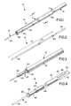
- a miniature coaxial contact, generally designated 10, embodying the present invention is shown as being terminated to a tri-lead coaxial cable, generally designated 12.
- the coaxial contact 10 includes a signal pin contact, generally designated 14, an overmolded in - sulator assembly, generally designated 16 (Fig. 4), and a tubular ground shield structure, generally designated 18.
- pin contact or signal pin 14 has a substantially uniform cross-section along a major or substantial portion 20 of its length.
- the cross-section of the pin along its major length is round.
- the pin also has a pair of spaced interruptions 22 which, in the illustrated embodiment, are provided in the form of flattened areas of the otherwise round configuration of the pin.
- the pin also has a flattened terminating end 24 opposite its distal or contact end 26.
- the terminating end 24 is flattened by a coining operation to provide a greater target area for bonding a signal wire 27 (Fig. 3) thereto, such as by brazing or welding as described hereinafter.
- Other con - figurations could be coined if desired such as a convex surface to maximize the contact pressure during the bonding operation or a concave surface to retain solder.
- FIG. 3 shows the general construction of the tri - lead coaxial cable 12 as well as its configura - tion immediately prior to termination to contact 10.
- the cable 12 includes a signal wire or core 27 surrounded by an insulating jacket 28.
- a pair of ground wires 30 run lengthwise of the coaxial cable adjacent insulating jacket 28 and inside an outer dielectric sheath 32 of the cable 12.
- a conductive shield 34 is located inside outer dielectric sheath 32 and surrounds and contacts ground wires 30 and insulating jacket 28.
- the outer dielectric sheath 32 and conductive shield 34 are cut-away, as at 36, to expose lengths of the ground wires 30, and insulating jacket 28 is cutaway, as at 38, to expose a length of signal wire 27.
- the signal wire and ground wires of the cable are "differentially stripped".
- insulating jacket 28 is stripped a given distance from the end of signal wire 27 so that the insulating jacket 28 extends a predetermined distance from the edge 36 of sheath 32.
- Ground wires 30 are cut - off at a length that is shorter than the length of exposed insulating jacket 28. This prevents shorting between the signal wire 27 and the ground wires 30.
- insulator 16 is shown overmolded about pin contact 14 rearwardly of contact end 26 and beyond terminating end 24. More particularly, a pair of insulator sections 40 and 42 define a gap 44 therebetween. The insulator sections are overmol - ded onto pin contact 14 in a correspondingly shaped mold, and of dielectric material such as plastic or the like. Forward insulator section 40 has a reduced diameter or relieved portion 46 for pur - poses described hereinafter.
- Rear insulator section 42 has a trough 48 ex - tending lengthwise of the insulator section (i.e., axially of the signal pin) along a portion thereof whereby the trough provides access to the top of terminating end 24 of signal pin 14.
- the inner walls 74 of the trough diverge from the bottom thereof, as shown in Figures 4 and 7, for purposes described hereinafter.
- the distal end of insulator section 42 has a flat surface 50 also for purposes described hereinafter.
- Insulator section 42 also has a pair of recesses 52 (Figs. 4 and 7) through the underside thereof opposite trough 48.
- the recesses 52 extend through the bottom of insulator section 42 to provide access to the bottom of terminating end 24 of pin 14.
- a pair of recesses 52 is provided so that the plastic between the reces - ses adequately supports the pin 14 while the signal wire 27 is bonded thereto.
- pin 14 It is desirable to be able to support pin 14 on opposite sides during overmolding. This can be done at the contact end 26 of the pin, in the gap 44 between insulator sections 40 and 42, and on the opposite sides of flat terminating end 24 that are exposed by trough 48 and recesses 52. By supporting pin 14 in such a manner, flash can be virtually eliminated from extending onto contact end 26 and terminating end 24. In addition, supporting the pin at three locations also helps to maintain the linearity of the pin.
- shield 18 includes a tubular forward portion 54 surrounding forward insulator section 40 (Fig. 4) and a channel - shaped section 56 housing rear insulator section 42, the prepared end of coaxial cable 12 as illustrated in Figure 3, and a portion of the un - prepared cable 12 located therein.
- the tubular forward portion 54 is split, as at 54a, lengthwise thereof, and the tubular portion is crimped onto forward insulator section 40 to retain the overmolded pin assembly therein.
- the metal of the tubular portion is corrugated in a "sawtoothed" fashion along split 54a, as at 58. After the crimping operation, the corrugations assist in retaining the overmolded pin assembly therein without substan - tial deformation of insulator section 40 which could change the impedance of the connector 10.
- Forward tubular portion 54 of the shield in - cludes a pair (only one being visible in Figure 5) of spring fingers 60 which are provided on opposite sides of the shield for engaging a portion of bore 80 of a complementary connector 82 (Fig. 9). Therefore, as described in relation to Figure 4, reduced diameter portion 46 of insulator section 40 is provided for accommodating movement of the spring fingers 60 radially inwardly during insertion of the coaxial connector 10 into bore 80a (Fig. 9).
- Each spring finger 60 has an outwardly convex or hemispherical distal contact end 60a. This con - figuration reduces the contact area which produces a high contact pressure for a given biasing force. This high contact pressure increases the reliability of the contact.
- Figure 6 shows the detail of the front edge of the ground tube 18 and insulator 16 as well as one of the spring fingers 60.
- the spring finger is integrally formed with the tubular portion 54 of the shield 18 and extends rearwardly therefrom in cantilever fashion.
- the widened root portion 70 of the spring finger and the circum - ferential band 72 of metal between spring finger 60 and the front edge 64 of ground tube 18 are dimensioned so that band 72 twists as spring finger 60 is deflected.
- the effective spring rate is equal to the combination of that of the spring fingers 60 plus the torsional effect of band 72. Consequently, the spring finger 60 can be made shorter yet still provide the desired contact force at its distal end 60a.
- the tapered forward end 62 of forward insulator section 40 projects beyond the forward end 64 of the tubular forward portion 54 of shield 18.
- the forward end 64 of the tubular portion 54 is crimped into reduced diameter portion 46 of the insulator section 40 behind the front shoulder 66 of the reduced diameter portion. Therefore, when the shielded assembly is inserted into bore 80, the tapered forward edge 62 of the insulator 16 acts as a lead - in to prevent the for - ward end 64 of the tubular portion from stubbing against the entry of the bore.
- Figure 5 also shows signal wire 27 of coaxial cable 12 positioned to rest on top of terminating end 24 of signal pin 14.
- the signal wire 27 is placed into trough 48, with the diverging inner walls 74 of the trough guiding the signal wire onto the terminating end 24 of the signal pin.
- the outer side walls 76 of rear insulator section 42 reduce the likelihood that rear portion 56 will contact either the signal pin 14 or signal wire 27 once the rear portion is closed as shown in Figure 1. That is, if rear portion 56 is deformed while being closed so that it would touch either signal pin 14 or signal wire 27, the side walls will be deformed by rear portion 56 and thus insulate the signal pin and signal wire.
- the signal wire 27 rests on top of flat surface 50 of insulator section 42.
- the signal wire 27 then can be bonded such as by brazing to the flattened termi - nating end 24 of the signal pin 14.
- rearward section 56 of shield 18 overlaps cable shield 34 to fully shield the termination and prevent RF emis - sions.
- the signal pin 14 is first formed to the desired shape as shown in Figure 2.
- the insulator 16 is then overmolded around the signal pin 14.
- the ground tube 18 is stamped and formed so that the front portion 54 is generally tube shaped and dimensioned slightly larger than in - sulator portion 40.
- the rear portion 56 is shaped in an open configuration ( Figure 5) to permit access to the termination portion 24 of signal pin 14 and the inner portion of ground tube 18 for terminating the signal wire 27 and drain wires 30 thereto, respectively.
- the front portion 54 of the ground tube is formed about the front insulator portion 40 to retain the insulator 16 and signal pin 14 thereto.
- the drain wires 30 are brazed to the rear portion 56 of the ground tube one at a time and the signal wire 27 is brazed to signal pin 14.
- the rear portion 56 of ground tube 18 is deformed to close ground tube 18 in a generally cylindrical shape.
- the respective wires are joined to the signal pin 14 and ground shield 18 by a combination of heat and pressure which actually effect a braze due to the presence of plated coatings on the components.
- pin 14 and shield 18 are nickel plated at least in the brazing areas
- signal wire 27 and ground wires 30 are of silver or silver plated material. Joining the wires to the respective portions of the signal pin and ground tube in this manner reduces the overall lateral cross - sectional area of the termination when compared to termination methods such as crimping or insulation displacement. It is contemplated that other means for terminating the drain wires and the signal wire, such as soldering, ultrasonic welding, thermo - compression welding, resistance welding or the like, could be utilized.
- a portion of a connector housing three of the coaxial contacts 10 is shown with the contacts mounted in bores 81 in an in - sulative housing, generally designated 84, at one end of a cable harness.
- a connector of this type would typically be terminated at each end of the cable harness.
- the housing has a receptacle cavity 85 for receiving a mating connector 82.
- the con - tact ends 24 of the pins 14 make contact with pairs of cantilevered arms 86 of a plurality of female electrical terminals, generally designated 88.
- Each female terminal is disposed in a pair of insulators 90 which, in turn, is mounted in a respective bore 80 of a conductor grounding connector housing 92.
- the housing is designed for mounting to a printed circuit board (not shown), with stand-offs 94 spacing the housing from the printed circuit board. It can be seen that female terminals 88 have solder tail portions 96 for insertion into holes in an appropriate printed circuit board for connection to appropriate circuit traces around or within the holes in the board. After the individual coaxial contacts are inserted into insulative housing 84, they are further secured therein by pouring an epoxy filler 97 into the rear cavity 98.
Landscapes
- Coupling Device And Connection With Printed Circuit (AREA)
- Multi-Conductor Connections (AREA)
Applications Claiming Priority (2)
| Application Number | Priority Date | Filing Date | Title |
|---|---|---|---|
| US07/792,537 US5203079A (en) | 1991-11-13 | 1991-11-13 | Method of terminating miniature coaxial electrical connector |
| US792537 | 1991-11-13 |
Publications (3)
| Publication Number | Publication Date |
|---|---|
| EP0542075A2 true EP0542075A2 (de) | 1993-05-19 |
| EP0542075A3 EP0542075A3 (en) | 1993-10-20 |
| EP0542075B1 EP0542075B1 (de) | 1996-04-10 |
Family
ID=25157254
Family Applications (1)
| Application Number | Title | Priority Date | Filing Date |
|---|---|---|---|
| EP92118722A Expired - Lifetime EP0542075B1 (de) | 1991-11-13 | 1992-11-02 | Verfahren zum Anschliessen eines elektrischen koaxialen Miniatursteckers und sich daraus ergebender Steckeranschluss |
Country Status (5)
| Country | Link |
|---|---|
| US (1) | US5203079A (de) |
| EP (1) | EP0542075B1 (de) |
| JP (1) | JP2617156B2 (de) |
| DE (1) | DE69209776T2 (de) |
| ES (1) | ES2086047T3 (de) |
Cited By (1)
| Publication number | Priority date | Publication date | Assignee | Title |
|---|---|---|---|---|
| KR101529255B1 (ko) * | 2012-07-20 | 2015-06-16 | 후루카와 덴키 고교 가부시키가이샤 | 압착 단자, 접속 구조체, 커넥터 및 압착 단자의 압착 방법 |
Families Citing this family (18)
| Publication number | Priority date | Publication date | Assignee | Title |
|---|---|---|---|---|
| US5670744A (en) * | 1994-08-30 | 1997-09-23 | Ritchey; Carey | Entry port systems for connecting co-axial cables to printed circuit boards |
| DE102005002707B4 (de) * | 2005-01-19 | 2007-07-26 | Infineon Technologies Ag | Verfahren zur Herstellung elektrischer Verbindungen in einem Halbleiterbauteil mittels koaxialer Mikroverbindungselemente |
| JP2012009229A (ja) | 2010-06-23 | 2012-01-12 | Jst Mfg Co Ltd | 同軸ケーブル用コンタクト及び端末処理方法 |
| WO2012030365A1 (en) * | 2010-08-31 | 2012-03-08 | 3M Innovative Properties Company | High density shielded electrical cable and other shielded cables, systems, and methods |
| US8887388B2 (en) | 2010-11-22 | 2014-11-18 | Andrew Llc | Method for interconnecting a coaxial connector with a solid outer conductor coaxial cable |
| US8876549B2 (en) | 2010-11-22 | 2014-11-04 | Andrew Llc | Capacitively coupled flat conductor connector |
| US8826525B2 (en) | 2010-11-22 | 2014-09-09 | Andrew Llc | Laser weld coaxial connector and interconnection method |
| US8453320B2 (en) | 2010-11-22 | 2013-06-04 | Andrew Llc | Method of interconnecting a coaxial connector to a coaxial cable via ultrasonic welding |
| US8365404B2 (en) | 2010-11-22 | 2013-02-05 | Andrew Llc | Method for ultrasonic welding a coaxial cable to a coaxial connector |
| US9728926B2 (en) | 2010-11-22 | 2017-08-08 | Commscope Technologies Llc | Method and apparatus for radial ultrasonic welding interconnected coaxial connector |
| US9761959B2 (en) | 2010-11-22 | 2017-09-12 | Commscope Technologies Llc | Ultrasonic weld coaxial connector |
| DE112017005036T5 (de) * | 2016-10-04 | 2019-08-01 | The Charles Stark Draper Laboratory, Inc. | Verfahren und Vorrichtung zur Herstellung eines Miniatur-Koaxialkabels sowie das Verbindungsverfahren des Miniatur-Koaxialkabels |
| US10944214B2 (en) | 2017-08-03 | 2021-03-09 | Amphenol Corporation | Cable connector for high speed interconnects |
| CN112514175B (zh) | 2018-04-02 | 2022-09-09 | 安达概念股份有限公司 | 受控阻抗顺应性线缆终端头 |
| CN116247455A (zh) | 2019-01-25 | 2023-06-09 | 富加宜(美国)有限责任公司 | 电连接器 |
| WO2020154526A1 (en) | 2019-01-25 | 2020-07-30 | Fci Usa Llc | I/o connector configured for cabled connection to the midboard |
| TWI888408B (zh) | 2019-09-19 | 2025-07-01 | 美商安芬諾股份有限公司 | 電連接器及連接纜線至基板的方法 |
| CN113258325A (zh) | 2020-01-28 | 2021-08-13 | 富加宜(美国)有限责任公司 | 高频中板连接器 |
Family Cites Families (11)
| Publication number | Priority date | Publication date | Assignee | Title |
|---|---|---|---|---|
| US3539976A (en) * | 1968-01-04 | 1970-11-10 | Amp Inc | Coaxial connector with controlled characteristic impedance |
| US3660805A (en) * | 1970-08-05 | 1972-05-02 | Molex Inc | Shielded cable connector and method of making the same |
| US4269469A (en) * | 1978-04-21 | 1981-05-26 | Souriau & Cie | Contact terminal connector |
| US4406512A (en) * | 1981-07-24 | 1983-09-27 | E. I. Du Pont De Nemours And Company | Triple row coax cable connector |
| JPS618981U (ja) * | 1984-06-22 | 1986-01-20 | 日本航空電子工業株式会社 | 同軸ケ−ブル用コネクタ |
| US4602830A (en) * | 1984-09-20 | 1986-07-29 | Amp Incorporated | Double row electrical connector |
| US4964814A (en) * | 1986-10-03 | 1990-10-23 | Minnesota Mining And Manufacturing Co. | Shielded and grounded connector system for coaxial cables |
| US4897046A (en) * | 1986-10-03 | 1990-01-30 | Minnesota Mining And Manufacturing Company | Shielded connector system for coaxial cables |
| US4889500A (en) * | 1988-05-23 | 1989-12-26 | Burndy Corporation | Controlled impedance connector assembly |
| US4941833A (en) * | 1988-10-06 | 1990-07-17 | Burndy Corporation | Controlled impedance plug and receptacle |
| US5060373A (en) * | 1989-08-22 | 1991-10-29 | The Phoenix Company Of Chicago, Inc. | Methods for making coaxial connectors |
-
1991
- 1991-11-13 US US07/792,537 patent/US5203079A/en not_active Expired - Fee Related
-
1992
- 1992-11-02 DE DE69209776T patent/DE69209776T2/de not_active Expired - Fee Related
- 1992-11-02 EP EP92118722A patent/EP0542075B1/de not_active Expired - Lifetime
- 1992-11-02 ES ES92118722T patent/ES2086047T3/es not_active Expired - Lifetime
- 1992-11-11 JP JP4325972A patent/JP2617156B2/ja not_active Expired - Lifetime
Cited By (1)
| Publication number | Priority date | Publication date | Assignee | Title |
|---|---|---|---|---|
| KR101529255B1 (ko) * | 2012-07-20 | 2015-06-16 | 후루카와 덴키 고교 가부시키가이샤 | 압착 단자, 접속 구조체, 커넥터 및 압착 단자의 압착 방법 |
Also Published As
| Publication number | Publication date |
|---|---|
| EP0542075A3 (en) | 1993-10-20 |
| ES2086047T3 (es) | 1996-06-16 |
| JP2617156B2 (ja) | 1997-06-04 |
| US5203079A (en) | 1993-04-20 |
| JPH0668939A (ja) | 1994-03-11 |
| DE69209776T2 (de) | 1997-04-17 |
| DE69209776D1 (de) | 1996-05-15 |
| EP0542075B1 (de) | 1996-04-10 |
Similar Documents
| Publication | Publication Date | Title |
|---|---|---|
| JP3015942B2 (ja) | 高速伝送線のシールド終端装置 | |
| JP3935878B2 (ja) | 改良された接地手段を備えたコネクタ | |
| US5203079A (en) | Method of terminating miniature coaxial electrical connector | |
| US6380485B1 (en) | Enhanced wire termination for twinax wires | |
| US5725387A (en) | System for terminating the shield of a high speed cable | |
| US5046952A (en) | Right angle connector for mounting to printed circuit board | |
| US5716236A (en) | System for terminating the shield of a high speed cable | |
| US5785555A (en) | System for terminating the shield of a high speed cable | |
| US5961348A (en) | System for terminating the shield of a high speed cable | |
| US5718607A (en) | System for terminating the shield of a high speed cable | |
| US5711686A (en) | System for terminating the shield of a high speed cable | |
| EP0072063B1 (de) | Zwei- oder dreireihiger Koaxialkabelverbinder | |
| US5768771A (en) | System for terminating the shield of a high speed cable | |
| US6364701B1 (en) | System for terminating the shield of a high speed cable | |
| US20100065327A1 (en) | Cable assembly with molded grounding bar and method of making same | |
| US5186656A (en) | Miniature coaxial electrical connector | |
| JP3425634B2 (ja) | 高速ケーブル用のシールド終端機構を備えた電気コネクタ | |
| KR100382175B1 (ko) | 동축 케이블 관리 시스템을 포함하는 전기 커넥터 |
Legal Events
| Date | Code | Title | Description |
|---|---|---|---|
| PUAI | Public reference made under article 153(3) epc to a published international application that has entered the european phase |
Free format text: ORIGINAL CODE: 0009012 |
|
| AK | Designated contracting states |
Kind code of ref document: A2 Designated state(s): DE ES FR GB IT |
|
| PUAL | Search report despatched |
Free format text: ORIGINAL CODE: 0009013 |
|
| AK | Designated contracting states |
Kind code of ref document: A3 Designated state(s): DE ES FR GB IT |
|
| 17P | Request for examination filed |
Effective date: 19940608 |
|
| 17Q | First examination report despatched |
Effective date: 19940914 |
|
| ITF | It: translation for a ep patent filed | ||
| GRAA | (expected) grant |
Free format text: ORIGINAL CODE: 0009210 |
|
| AK | Designated contracting states |
Kind code of ref document: B1 Designated state(s): DE ES FR GB IT |
|
| ET | Fr: translation filed | ||
| REF | Corresponds to: |
Ref document number: 69209776 Country of ref document: DE Date of ref document: 19960515 |
|
| REG | Reference to a national code |
Ref country code: ES Ref legal event code: FG2A Ref document number: 2086047 Country of ref document: ES Kind code of ref document: T3 |
|
| GRAH | Despatch of communication of intention to grant a patent |
Free format text: ORIGINAL CODE: EPIDOS IGRA |
|
| PLBE | No opposition filed within time limit |
Free format text: ORIGINAL CODE: 0009261 |
|
| STAA | Information on the status of an ep patent application or granted ep patent |
Free format text: STATUS: NO OPPOSITION FILED WITHIN TIME LIMIT |
|
| 26N | No opposition filed | ||
| PGFP | Annual fee paid to national office [announced via postgrant information from national office to epo] |
Ref country code: GB Payment date: 20001004 Year of fee payment: 9 |
|
| PGFP | Annual fee paid to national office [announced via postgrant information from national office to epo] |
Ref country code: FR Payment date: 20001107 Year of fee payment: 9 |
|
| PGFP | Annual fee paid to national office [announced via postgrant information from national office to epo] |
Ref country code: ES Payment date: 20001121 Year of fee payment: 9 |
|
| PGFP | Annual fee paid to national office [announced via postgrant information from national office to epo] |
Ref country code: DE Payment date: 20001124 Year of fee payment: 9 |
|
| PG25 | Lapsed in a contracting state [announced via postgrant information from national office to epo] |
Ref country code: GB Free format text: LAPSE BECAUSE OF NON-PAYMENT OF DUE FEES Effective date: 20011102 |
|
| PG25 | Lapsed in a contracting state [announced via postgrant information from national office to epo] |
Ref country code: ES Free format text: LAPSE BECAUSE OF NON-PAYMENT OF DUE FEES Effective date: 20011103 |
|
| REG | Reference to a national code |
Ref country code: GB Ref legal event code: IF02 |
|
| GBPC | Gb: european patent ceased through non-payment of renewal fee |
Effective date: 20011102 |
|
| PG25 | Lapsed in a contracting state [announced via postgrant information from national office to epo] |
Ref country code: DE Free format text: LAPSE BECAUSE OF NON-PAYMENT OF DUE FEES Effective date: 20020702 |
|
| PG25 | Lapsed in a contracting state [announced via postgrant information from national office to epo] |
Ref country code: FR Free format text: LAPSE BECAUSE OF NON-PAYMENT OF DUE FEES Effective date: 20020730 |
|
| REG | Reference to a national code |
Ref country code: FR Ref legal event code: ST |
|
| REG | Reference to a national code |
Ref country code: FR Ref legal event code: ST |
|
| REG | Reference to a national code |
Ref country code: ES Ref legal event code: FD2A Effective date: 20021213 |
|
| PG25 | Lapsed in a contracting state [announced via postgrant information from national office to epo] |
Ref country code: IT Free format text: LAPSE BECAUSE OF NON-PAYMENT OF DUE FEES;WARNING: LAPSES OF ITALIAN PATENTS WITH EFFECTIVE DATE BEFORE 2007 MAY HAVE OCCURRED AT ANY TIME BEFORE 2007. THE CORRECT EFFECTIVE DATE MAY BE DIFFERENT FROM THE ONE RECORDED. Effective date: 20051102 |