EP0542128A2 - Conducteur de chauffage électrique destiné à être monté dans un appareil de chauffage par infrarouge - Google Patents
Conducteur de chauffage électrique destiné à être monté dans un appareil de chauffage par infrarouge Download PDFInfo
- Publication number
- EP0542128A2 EP0542128A2 EP92118934A EP92118934A EP0542128A2 EP 0542128 A2 EP0542128 A2 EP 0542128A2 EP 92118934 A EP92118934 A EP 92118934A EP 92118934 A EP92118934 A EP 92118934A EP 0542128 A2 EP0542128 A2 EP 0542128A2
- Authority
- EP
- European Patent Office
- Prior art keywords
- heating conductor
- heating
- conductor according
- conductors
- individual
- Prior art date
- Legal status (The legal status is an assumption and is not a legal conclusion. Google has not performed a legal analysis and makes no representation as to the accuracy of the status listed.)
- Granted
Links
Images
Classifications
-
- H—ELECTRICITY
- H05—ELECTRIC TECHNIQUES NOT OTHERWISE PROVIDED FOR
- H05B—ELECTRIC HEATING; ELECTRIC LIGHT SOURCES NOT OTHERWISE PROVIDED FOR; CIRCUIT ARRANGEMENTS FOR ELECTRIC LIGHT SOURCES, IN GENERAL
- H05B3/00—Ohmic-resistance heating
- H05B3/68—Heating arrangements specially adapted for cooking plates or analogous hot-plates
- H05B3/74—Non-metallic plates, e.g. vitroceramic, ceramic or glassceramic hobs, also including power or control circuits
- H05B3/748—Resistive heating elements, i.e. heating elements exposed to the air, e.g. coil wire heater
Definitions
- the invention relates to a radiant heating conductor, in particular an electric radiant heater.
- Radiant heaters of this type are used for heating plates, in particular glass ceramic plates. They are arranged on an insulating support at a distance from the plate.
- a radiation heating device has become known, in which the heating conductor is divided into several individual wires which are twisted together. You want to increase the life of the radiator, because the heat radiation is spread over a larger area. The specific surface load is reduced by increasing the surface while the overall cross section of the heating conductor remains the same. If several individual wires are twisted or stranded, however, the radiation is also impeded in their radiation, at least on the surfaces facing one another. This document also proposes a different cross-sectional design, for example a star shape of the wires. These are difficult to manufacture and process.
- Such heating conductors are also known from DE-A-35 09 985.
- heating conductors For radiant heaters in which the heating conductor is sealed off from the atmosphere by being enclosed in a quartz tube, relatively thin heating conductors can be used which assume very high temperatures and therefore radiate in the range of visible light, especially if, for example, a halogenated gas atmosphere in the Tube the heating coil is also protected against evaporation.
- halogen lamps are used for cooking purposes, but are expensive and also pose control problems.
- GB-A-2 074 828 attempts to improve the radiation behavior by using a non-circular helix shape.
- the object of the invention is to provide a radiant heater which, although it is exposed to the atmosphere, has a shortened glow-up time without sacrificing service life.
- the low mass / performance ratio makes it possible to shorten the glow time considerably.
- the result is a rapidly glowing heat conductor, which has a smaller overall cross-sectional area at a substantially the same final surface temperature as a conventional single-wire heat conductor with a circular cross-section. It has been found that the delay in the glowing is largely caused by the thermal inertia of the heating conductor itself, provided that heat dissipation by the insulating support is kept to an acceptable level.
- the advantages of the invention are achieved to a particular degree if the radiator is practically only resting on an insulating support with good thermal insulation properties.
- heating conductors designed according to the invention did not have a sufficient service life, even if the heating conductors designed according to the invention consisted of several individual conductors connected in parallel. It was even found that the heating conductor lasts longer when it is thin when it is otherwise comparable. Although this has already been recognized in DE-A-39 11 761, the specific surface load has been reduced there and the effect on the twisting of the individual wires has also been reduced. It was also found that heating conductors made of an iron-chromium-aluminum alloy show better values when their aluminum content is relatively high, for example above 4%, preferably about 5%. Your specific heat capacity value of approx. 0.53 [kJ / kg. K] in the range of 300 - 1100 K forms the basis for the value of the mass-power ratio.
- the heating conductors can also be designed as flat conductors and can also be applied to the insulating support by spraying, such as plasma spraying.
- spraying such as plasma spraying.
- waveguides for example thin tubes made of resistance material
- sintered or foil casting could also be used in addition to plasma spraying.
- the attachment to the insulating body could be carried out by pouring, stapling, nailing, clamping, snapping or other form-fitting holding methods, possibly also by means of a holding structure, such as a rod, a lattice structure or preferably a helix become, while when applying as a layer anchoring is appropriate by appropriate surface design of the insulating support.
- the geometry of the application of the heating conductors to the insulating support can comprise several, for example ten, parallel conductors which are arranged in linear, meandering or spiral paths.
- the arrangement could also include a stranded, stranded or coaxial spiral geometry.
- Flat wires are corrugated or preferably coiled and can be arranged in a meandering, spiral or other configuration when standing or lying. Ribbed or pimpled shapes are also suitable for the production from film and a layer application from pastes etc.
- the heating conductor is exposed to as little thermal movement or expansion as possible and the curvature of the heating conductor wall is relatively large in order to keep the aluminum oxide layer that forms on the heating conductor. For this reason, any contact with the heating conductor by elements that scratch it during thermal expansion etc. should be avoided so as not to damage the oxide layer. This protects the heating conductor and enables a long service life.
- the heating conductor can consist of a plurality of individual conductors which are connected in parallel to one another and interact in a network-like manner.
- This arrangement allows a specific surface load of the heating conductor and thus essentially the same surface temperature, the total heating conductor cross-sectional area compared to a single wire significantly lower.
- the net-like arrangement creates the advantage that on the one hand the individual heating conductors form a coherent structure, but on the other hand hardly shield each other, since they only touch one another at a time and hardly any shadowing occurs.
- a formation of an oxide skin for example made of aluminum oxide, which occurs in most heating conductor materials and is also important for the service life, ensures that the wires are practically electrically insulated from one another at their crossing points.
- the heating conductor can consist of a woven, braided or knitted fabric of any binding structure.
- a hose braid is particularly preferred, the individual conductors of which are interwoven in the form of spirals which are rotated in opposite directions.
- Such a hose mesh is quite stable in itself, although it is flexible enough to be spiral, meandering or the like on an insulating support. to be arranged without fear of the hose kinking or being compressed.
- the hose network can also be formed from groups of individual conductors running parallel to one another. Another advantage is that the relatively small wire diameter Individual conductor that holds the oxide skin protecting the heating conductor very well and is not caused to rub off or flake off by mechanical or thermal movements.
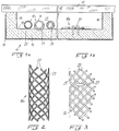
- the radiant heater 11 is intended for an electric cooking appliance and pressed onto the underside of a glass ceramic plate 12 on which cooking vessels can stand.
- the radiant heater 11 contains, in a sheet metal shell 13, an insulating body 14 made of thermally well-insulating and high-temperature-resistant insulating material, for example a microporous silica airgel that can be reinforced with ceramic fibers.
- Heating conductors 18a, 18b are arranged on the bottom 17 of the radiation space 15 which forms in the insulating support 14 and is surrounded by its edge 16.
- One or more heating conductors can be arranged, which are formed in FIG. 1a in the form of a tubular braid, the network-like surface of which consists of individual wires interwoven with one another or of strands of individual wires.
- FIG. 2 it can be seen that several strands of two individual wires each run parallel to one another in a helical shape and are interwoven with corresponding strands running in the opposite spiral direction.
- the tubular braid is relatively loose, so that stitches are formed with a free mesh area 21 which is at least half as large as the corresponding area occupied by the individual wires 20, but preferably larger than this. This ensures that radiation originating or reflected from the rear can exit through these mesh spaces 21.
- the number of individual wires is determined by the number of wires in the strands and by the number of strands running parallel to each other in each spiral direction. It can be, for example, twelve, as is indicated schematically in FIG. 1a.
- the heating conductor 18a made of hose mesh lies on the bottom 17 of the insulating body 14 and can be clamped or the like there. be attached, paying attention to the lowest possible thermal contact with the surface.
- Its inner diameter is somewhat larger than the outer diameter of the heating conductor 18a and its lower part 23 is embedded in the insulating body 14 and thus holds the heating conductor largely in a contact-free manner, but well secured in position.
- a holding or support spiral 24 can also be drawn into the interior of the hose mesh, which in turn then clamps the clips o .
- the arrangement of the heating conductors on the insulating support can or the like in spiral, meandering. respectively.
- FIG. 1b shows a heating conductor 18b which is designed in the form of a network-like flat braid made of individual conductors 20. It can be a flat strip, of which only one side is shown in FIGS. 1b and 3, but which on the other side also has an outer edge 26 closed by individual conductor bends 25, so that the individual conductors 20 pass from terminal to terminal.
- This tape can be fastened to the insulating support by clips 27.
- connection is made jointly at one end, so that all individual conductors are connected in parallel to each other. Since they are all at the same potential, contact between the individual conductors does not lead to a short circuit, so that their attachment is not a major problem and they cannot have any significant differential voltage at each other even at the crossing points.
- the individual conductors consist of an iron-chromium-aluminum alloy with an aluminum content of approx. 5% and have a diameter and length such that the total mass of the heating conductor consisting of individual wires is less than 7 from connection to connection. 10 ⁇ 3 g / W. If ten individual conductors connected in parallel are arranged in a radiant heater with a diameter of 180 mm and a nominal output of 1700 watts at 230 V and a surface load of 6 W / cm, the heating conductor has a total mass of 9.1 g and accordingly a length of each ten single conductors of 5.12 m, ie a sum of the individual wire lengths of 51.2 m with a wire diameter of 0.176 mm.
- the use of only one wire of 0.817 mm diameter would give the mass of the wire at 41.7 g in order to obtain the same surface load, while three wires have a total mass of 20.16 g with a diameter of approx. would result in 0.4 mm.
- the mass of the heating conductor can be substantially reduced by the invention while maintaining the surface temperature, although the wire diameter is reduced and the total length of the individual conductors increases.
- the length of the heating conductor itself does not increase if you consider the length of the overall conductor. While the ten individual conductors each have a length of 5.12 m, in the same example the individual wire would be 11.03 m long. It is therefore possible to use a hose network in which the individual coils are not as close together as is usually the case with a heating coil, so that it can be relatively loose and form enough space between them to be irradiated.
- a major advantage of the network-like construction of the heating conductor from individual conductors is that the individual conductors can be relatively thin, but gain stability and manageability due to the braided weave. Furthermore, they are thereby fixed in their position relative to one another without having to rely on fastening means for this function.
- a very significant advantage is the fact that the individual conductors essentially only touch one another at the crossing points, i.e. can radiate freely over the vast majority of their total length and scope. In contrast to a stranded wire, in which the conductors are directed towards each other over a very large part of their circumference and therefore cannot radiate freely, this is a very important advantage.
- the embodiments shown in FIGS. 2 and 3 are only examples.
- All braids, fabrics or knitted fabrics of different types of weave can be used.
- a particular advantage is the fact that the aluminum content in the heating conductor alloy forms an oxide skin on the individual conductors, which not only protects the heating conductor from further oxidation, but also has an insulating effect, at least in the voltage range that can occur between the individual conductors that there is normally no electrical connection at the crossing points.
- the support and holding coils 22, 24 can also be connected in parallel to the heating conductor in order to bring them to the same potential as the actual heating conductor, and can absorb, for example, a tenth of the total power.
- This performance share of the holding or Supporting coils can be controlled via a corresponding extension factor of the coils, ie more or less tight winding or via lower conductivity values and the diameter of these coils.
- fastening means could also be formed in the same way, for example by providing loops or tips which are bent downwards in the edge region and which are pressed or embedded into the insulating carrier material.
- the iron-chromium-aluminum alloy described for the heating conductor has been assumed, which has a specific heat capacity of approx. 0.53 kJ / kg.
- K has a mean value over the range between 300 and 1100 K (approx. 20 - 800 ° C). Since the mass / power ratio is dependent on the specific heat capacity value c, it changes in reverse proportion to the change in the heat capacity value (with 1 through c).
- a heating conductor designed in this way assumes an annealing temperature within approximately 3 seconds, which is the case at approximately 1100 K (approximately 800 ° C), while the maximum temperature exceeds 1300 K (approximately 1000 ° C), e.g. should be around 1350 K (1050 ° C).
- the mass / performance ratio is always based on the nominal output of the heating element concerned, i.e. not an output that is reduced by control or regulation or that is temporarily increased by special measures. It is a major advantage of the invention that the heating conductor configuration is electronic or other circuitry measures for temporary performance changes are not necessary.
- the surface of the thin, parallel-connected individual conductors which is large in relation to their mass, and which can be wires, but also flat strips, ensures favorable radiation conditions so that the maximum permissible temperatures are not exceeded and the service life is therefore sufficient.
- a ratio of width to thickness of 10 should not be undercut if possible. He can in the manner already described by spraying, or the like from a film. be made. In this embodiment, only about half of the surface is arranged to radiate freely, while this is a much larger proportion when arranging individual wires, as shown in the left half of the drawing. In the case of training as a helix, possibly as a multiple helix or as a standing flat wire, this percentage can be increased even further, which has advantages for the radiation and thus also for the specific surface load on the heating conductor surface.
- a heating conductor according to the invention could only be arranged in an annular area around another heating conductor, which can be of conventional design.
- the nominal power specification relates only to the partial power of the radiant heater which is designed to be rapidly glowing in accordance with the invention.
Landscapes
- Chemical & Material Sciences (AREA)
- Engineering & Computer Science (AREA)
- Ceramic Engineering (AREA)
- Resistance Heating (AREA)
- Surface Heating Bodies (AREA)
Priority Applications (1)
| Application Number | Priority Date | Filing Date | Title |
|---|---|---|---|
| DE9218244U DE9218244U1 (de) | 1991-11-13 | 1992-11-05 | Strahlungs-heizleiter, insbesondere eines elektrischen strahlungsheizkoerpers |
Applications Claiming Priority (4)
| Application Number | Priority Date | Filing Date | Title |
|---|---|---|---|
| DE4137251 | 1991-11-13 | ||
| DE4137250 | 1991-11-13 | ||
| DE19914137250 DE4137250A1 (de) | 1991-11-13 | 1991-11-13 | Strahlungs-heizleiter, insbesondere eines elektrischen strahlungsheitzkoerpers |
| DE19914137251 DE4137251A1 (de) | 1991-11-13 | 1991-11-13 | Strahlungs-heizleiter, insbesondere eines elektrischen strahlungsheizkoerpers |
Publications (3)
| Publication Number | Publication Date |
|---|---|
| EP0542128A2 true EP0542128A2 (fr) | 1993-05-19 |
| EP0542128A3 EP0542128A3 (en) | 1993-06-09 |
| EP0542128B1 EP0542128B1 (fr) | 1995-09-06 |
Family
ID=25909054
Family Applications (1)
| Application Number | Title | Priority Date | Filing Date |
|---|---|---|---|
| EP92118934A Expired - Lifetime EP0542128B1 (fr) | 1991-11-13 | 1992-11-05 | Conducteur de chauffage électrique destiné à être monté dans un appareil de chauffage par infrarouge |
Country Status (4)
| Country | Link |
|---|---|
| EP (1) | EP0542128B1 (fr) |
| AT (1) | ATE127648T1 (fr) |
| DE (1) | DE59203572D1 (fr) |
| ES (1) | ES2077329T3 (fr) |
Cited By (3)
| Publication number | Priority date | Publication date | Assignee | Title |
|---|---|---|---|---|
| DE102004049184A1 (de) * | 2004-10-08 | 2006-04-13 | BSH Bosch und Siemens Hausgeräte GmbH | Kochfeld sowie Verfahren zur Herstellung eines Kochfelds |
| WO2009027042A1 (fr) | 2007-08-24 | 2009-03-05 | E.G.O. Elektro-Gerätebau GmbH | Dispositif de chauffage, procédé pour faire fonctionner un dispositif de chauffage et appareil de chauffage électrique appartenant à un tel dispositif de chauffage |
| EP4435326A1 (fr) | 2023-03-24 | 2024-09-25 | E.G.O. Elektro-Gerätebau GmbH | Four de cuisson |
Family Cites Families (6)
| Publication number | Priority date | Publication date | Assignee | Title |
|---|---|---|---|---|
| US3345498A (en) * | 1965-02-01 | 1967-10-03 | Gen Motors Corp | Infrared surface heating unit |
| US3991298A (en) * | 1975-07-28 | 1976-11-09 | Gould Inc. | Heating unit for a ceramic top electric range |
| DE2551137C2 (de) * | 1975-11-14 | 1986-04-24 | E.G.O. Elektro-Geräte Blanc u. Fischer, 7519 Oberderdingen | Elektrischer Strahlungsheizkörper für Glaskeramikkochplatten |
| US4034206A (en) * | 1976-05-11 | 1977-07-05 | Gould Inc. | Range top element |
| US4292504A (en) * | 1979-10-02 | 1981-09-29 | Tutco, Inc. | Expanded metal electric heating element with edge support |
| DE3820691A1 (de) * | 1988-06-18 | 1989-12-21 | Ako Werke Gmbh & Co | Strahlungsheizkoerper |
-
1992
- 1992-11-05 EP EP92118934A patent/EP0542128B1/fr not_active Expired - Lifetime
- 1992-11-05 ES ES92118934T patent/ES2077329T3/es not_active Expired - Lifetime
- 1992-11-05 AT AT92118934T patent/ATE127648T1/de active
- 1992-11-05 DE DE59203572T patent/DE59203572D1/de not_active Expired - Lifetime
Cited By (5)
| Publication number | Priority date | Publication date | Assignee | Title |
|---|---|---|---|---|
| DE102004049184A1 (de) * | 2004-10-08 | 2006-04-13 | BSH Bosch und Siemens Hausgeräte GmbH | Kochfeld sowie Verfahren zur Herstellung eines Kochfelds |
| WO2009027042A1 (fr) | 2007-08-24 | 2009-03-05 | E.G.O. Elektro-Gerätebau GmbH | Dispositif de chauffage, procédé pour faire fonctionner un dispositif de chauffage et appareil de chauffage électrique appartenant à un tel dispositif de chauffage |
| DE102007040891A1 (de) | 2007-08-24 | 2009-04-30 | E.G.O. Elektro-Gerätebau GmbH | Heizeinrichtung, Verfahren zum Betrieb einer Heizeinrichtung und Elektrowärmegerät mit einer solchen Heizeinrichtung |
| EP4435326A1 (fr) | 2023-03-24 | 2024-09-25 | E.G.O. Elektro-Gerätebau GmbH | Four de cuisson |
| DE102023107504A1 (de) | 2023-03-24 | 2024-10-10 | E.G.O. Elektro-Gerätebau GmbH | Backofen |
Also Published As
| Publication number | Publication date |
|---|---|
| EP0542128B1 (fr) | 1995-09-06 |
| EP0542128A3 (en) | 1993-06-09 |
| ATE127648T1 (de) | 1995-09-15 |
| ES2077329T3 (es) | 1995-11-16 |
| DE59203572D1 (de) | 1995-10-12 |
Similar Documents
| Publication | Publication Date | Title |
|---|---|---|
| DE3406604C1 (de) | Heizeinrichtung fuer Strahlungsheizstellen mit elektrischen Strahlungsheizelementen | |
| DE2849266C2 (de) | Elektrischer Heizkörper für gasförmige Medien | |
| DE2205132C3 (de) | Elektrokochgerät | |
| EP0590315B1 (fr) | Elément chauffant, en particulier pour appareils de cuisine | |
| CH634451A5 (de) | Strahlungs-heizeinheit. | |
| DE3004187A1 (de) | Strahlungsheizer fuer herde mit ebenen kochplatten | |
| EP0490289A1 (fr) | Radiateur électrique notamment radiateur à rayonnement | |
| DE4229373A1 (de) | Heizkörper, insbesondere für Kochgeräte | |
| DE8133341U1 (de) | Elektrischer strahlungsheizer fuer herde mit glaskeramikdeckplatten | |
| DE9113992U1 (de) | Strahlungs-Heizeinheit | |
| DE2729929B2 (de) | Strahlungs-Heizeinheit für Glaskeramik-Elektrokochgeräte | |
| EP0303854B1 (fr) | Radiateur électrique | |
| EP0542128B1 (fr) | Conducteur de chauffage électrique destiné à être monté dans un appareil de chauffage par infrarouge | |
| DE2823059A1 (de) | Temperaturfuehlvorrichtung, insbesondere fuer geraete zur erwaermung oder erhitzung von nahrungsmitteln | |
| DE69405834T2 (de) | Elektrischer Wärmestrahler | |
| DE4137251A1 (de) | Strahlungs-heizleiter, insbesondere eines elektrischen strahlungsheizkoerpers | |
| DE69606519T2 (de) | Heizkabel mit variablem Leistungsbegrenzer | |
| DE9218244U1 (de) | Strahlungs-heizleiter, insbesondere eines elektrischen strahlungsheizkoerpers | |
| DE4137250A1 (de) | Strahlungs-heizleiter, insbesondere eines elektrischen strahlungsheitzkoerpers | |
| DE2820138C2 (fr) | ||
| DE29807833U1 (de) | Elektrische Strahlungsheizungen | |
| DE19812188C1 (de) | Elektrisch betreibbarer, stabförmiger Infrarotstrahler | |
| DE4030183A1 (de) | Elektrisches heizkabel | |
| DE2445889C3 (de) | Elektrischer Heizkörper | |
| DE1946753C3 (de) | Elektrisch beheizbares Band |
Legal Events
| Date | Code | Title | Description |
|---|---|---|---|
| PUAI | Public reference made under article 153(3) epc to a published international application that has entered the european phase |
Free format text: ORIGINAL CODE: 0009012 |
|
| PUAL | Search report despatched |
Free format text: ORIGINAL CODE: 0009013 |
|
| AK | Designated contracting states |
Kind code of ref document: A2 Designated state(s): AT CH DE ES FR GB IT LI SE |
|
| AK | Designated contracting states |
Kind code of ref document: A3 Designated state(s): AT CH DE ES FR GB IT LI SE |
|
| 17P | Request for examination filed |
Effective date: 19930525 |
|
| RAP1 | Party data changed (applicant data changed or rights of an application transferred) |
Owner name: E.G.O. ELEKTRO-GERAETE BLANC UND FISCHER GMBH & CO |
|
| 17Q | First examination report despatched |
Effective date: 19941017 |
|
| GRAA | (expected) grant |
Free format text: ORIGINAL CODE: 0009210 |
|
| AK | Designated contracting states |
Kind code of ref document: B1 Designated state(s): AT CH DE ES FR GB IT LI SE |
|
| REF | Corresponds to: |
Ref document number: 127648 Country of ref document: AT Date of ref document: 19950915 Kind code of ref document: T |
|
| REF | Corresponds to: |
Ref document number: 59203572 Country of ref document: DE Date of ref document: 19951012 |
|
| ET | Fr: translation filed | ||
| REG | Reference to a national code |
Ref country code: ES Ref legal event code: FG2A Ref document number: 2077329 Country of ref document: ES Kind code of ref document: T3 |
|
| ITF | It: translation for a ep patent filed | ||
| PG25 | Lapsed in a contracting state [announced via postgrant information from national office to epo] |
Ref country code: SE Effective date: 19951206 |
|
| GBT | Gb: translation of ep patent filed (gb section 77(6)(a)/1977) |
Effective date: 19951113 |
|
| PLBQ | Unpublished change to opponent data |
Free format text: ORIGINAL CODE: EPIDOS OPPO |
|
| PLBI | Opposition filed |
Free format text: ORIGINAL CODE: 0009260 |
|
| PLBF | Reply of patent proprietor to notice(s) of opposition |
Free format text: ORIGINAL CODE: EPIDOS OBSO |
|
| 26 | Opposition filed |
Opponent name: CERAMASPEED LIMITED Effective date: 19960531 |
|
| PLBF | Reply of patent proprietor to notice(s) of opposition |
Free format text: ORIGINAL CODE: EPIDOS OBSO |
|
| RAP2 | Party data changed (patent owner data changed or rights of a patent transferred) |
Owner name: E.G.O. ELEKTRO-GERAETEBAU GMBH |
|
| PLBL | Opposition procedure terminated |
Free format text: ORIGINAL CODE: EPIDOS OPPC |
|
| RDAH | Patent revoked |
Free format text: ORIGINAL CODE: EPIDOS REVO |
|
| RDAH | Patent revoked |
Free format text: ORIGINAL CODE: EPIDOS REVO |
|
| PLBM | Termination of opposition procedure: date of legal effect published |
Free format text: ORIGINAL CODE: 0009276 |
|
| STAA | Information on the status of an ep patent application or granted ep patent |
Free format text: STATUS: OPPOSITION PROCEDURE CLOSED |
|
| 27C | Opposition proceedings terminated |
Effective date: 19971102 |
|
| REG | Reference to a national code |
Ref country code: CH Ref legal event code: PFA Free format text: E.G.O. ELEKTRO-GERAETE BLANC UND FISCHER GMBH & CO. KG TRANSFER- E.G.O. ELEKTRO-GER-TEBAU GMBH |
|
| REG | Reference to a national code |
Ref country code: GB Ref legal event code: IF02 |
|
| PGFP | Annual fee paid to national office [announced via postgrant information from national office to epo] |
Ref country code: FR Payment date: 20101130 Year of fee payment: 19 Ref country code: AT Payment date: 20101119 Year of fee payment: 19 |
|
| PGFP | Annual fee paid to national office [announced via postgrant information from national office to epo] |
Ref country code: DE Payment date: 20101119 Year of fee payment: 19 Ref country code: CH Payment date: 20101124 Year of fee payment: 19 |
|
| PGFP | Annual fee paid to national office [announced via postgrant information from national office to epo] |
Ref country code: GB Payment date: 20101123 Year of fee payment: 19 Ref country code: IT Payment date: 20101124 Year of fee payment: 19 |
|
| PGFP | Annual fee paid to national office [announced via postgrant information from national office to epo] |
Ref country code: ES Payment date: 20101123 Year of fee payment: 19 |
|
| REG | Reference to a national code |
Ref country code: CH Ref legal event code: PL |
|
| GBPC | Gb: european patent ceased through non-payment of renewal fee |
Effective date: 20111105 |
|
| PG25 | Lapsed in a contracting state [announced via postgrant information from national office to epo] |
Ref country code: LI Free format text: LAPSE BECAUSE OF NON-PAYMENT OF DUE FEES Effective date: 20111130 Ref country code: CH Free format text: LAPSE BECAUSE OF NON-PAYMENT OF DUE FEES Effective date: 20111130 |
|
| REG | Reference to a national code |
Ref country code: FR Ref legal event code: ST Effective date: 20120731 |
|
| PG25 | Lapsed in a contracting state [announced via postgrant information from national office to epo] |
Ref country code: IT Free format text: LAPSE BECAUSE OF NON-PAYMENT OF DUE FEES Effective date: 20111105 |
|
| REG | Reference to a national code |
Ref country code: DE Ref legal event code: R119 Ref document number: 59203572 Country of ref document: DE Effective date: 20120601 |
|
| PG25 | Lapsed in a contracting state [announced via postgrant information from national office to epo] |
Ref country code: GB Free format text: LAPSE BECAUSE OF NON-PAYMENT OF DUE FEES Effective date: 20111105 |
|
| REG | Reference to a national code |
Ref country code: AT Ref legal event code: MM01 Ref document number: 127648 Country of ref document: AT Kind code of ref document: T Effective date: 20111105 |
|
| PG25 | Lapsed in a contracting state [announced via postgrant information from national office to epo] |
Ref country code: FR Free format text: LAPSE BECAUSE OF NON-PAYMENT OF DUE FEES Effective date: 20111130 |
|
| PG25 | Lapsed in a contracting state [announced via postgrant information from national office to epo] |
Ref country code: AT Free format text: LAPSE BECAUSE OF NON-PAYMENT OF DUE FEES Effective date: 20111105 |
|
| REG | Reference to a national code |
Ref country code: ES Ref legal event code: FD2A Effective date: 20130603 |
|
| PG25 | Lapsed in a contracting state [announced via postgrant information from national office to epo] |
Ref country code: DE Free format text: LAPSE BECAUSE OF NON-PAYMENT OF DUE FEES Effective date: 20120601 |
|
| PG25 | Lapsed in a contracting state [announced via postgrant information from national office to epo] |
Ref country code: ES Free format text: LAPSE BECAUSE OF NON-PAYMENT OF DUE FEES Effective date: 20111106 |