EP0542382A1 - Verfahren zum Herstellen von Walzgut aus sauerstofffreiem Kupfer - Google Patents
Verfahren zum Herstellen von Walzgut aus sauerstofffreiem Kupfer Download PDFInfo
- Publication number
- EP0542382A1 EP0542382A1 EP92250020A EP92250020A EP0542382A1 EP 0542382 A1 EP0542382 A1 EP 0542382A1 EP 92250020 A EP92250020 A EP 92250020A EP 92250020 A EP92250020 A EP 92250020A EP 0542382 A1 EP0542382 A1 EP 0542382A1
- Authority
- EP
- European Patent Office
- Prior art keywords
- casting
- deformation
- rolling
- oxygen
- strip
- Prior art date
- Legal status (The legal status is an assumption and is not a legal conclusion. Google has not performed a legal analysis and makes no representation as to the accuracy of the status listed.)
- Granted
Links
Images
Classifications
-
- B—PERFORMING OPERATIONS; TRANSPORTING
- B22—CASTING; POWDER METALLURGY
- B22D—CASTING OF METALS; CASTING OF OTHER SUBSTANCES BY THE SAME PROCESSES OR DEVICES
- B22D11/00—Continuous casting of metals, i.e. casting in indefinite lengths
- B22D11/06—Continuous casting of metals, i.e. casting in indefinite lengths into moulds with travelling walls, e.g. with rolls, plates, belts, caterpillars
- B22D11/0637—Accessories therefor
- B22D11/0697—Accessories therefor for casting in a protected atmosphere
-
- B—PERFORMING OPERATIONS; TRANSPORTING
- B21—MECHANICAL METAL-WORKING WITHOUT ESSENTIALLY REMOVING MATERIAL; PUNCHING METAL
- B21B—ROLLING OF METAL
- B21B1/00—Metal-rolling methods or mills for making semi-finished products of solid or profiled cross-section; Sequence of operations in milling trains; Layout of rolling-mill plant, e.g. grouping of stands; Succession of passes or of sectional pass alternations
- B21B1/46—Metal-rolling methods or mills for making semi-finished products of solid or profiled cross-section; Sequence of operations in milling trains; Layout of rolling-mill plant, e.g. grouping of stands; Succession of passes or of sectional pass alternations for rolling metal immediately subsequent to continuous casting
- B21B1/463—Metal-rolling methods or mills for making semi-finished products of solid or profiled cross-section; Sequence of operations in milling trains; Layout of rolling-mill plant, e.g. grouping of stands; Succession of passes or of sectional pass alternations for rolling metal immediately subsequent to continuous casting in a continuous process, i.e. the cast not being cut before rolling
-
- B—PERFORMING OPERATIONS; TRANSPORTING
- B21—MECHANICAL METAL-WORKING WITHOUT ESSENTIALLY REMOVING MATERIAL; PUNCHING METAL
- B21B—ROLLING OF METAL
- B21B3/00—Rolling materials of special alloys so far as the composition of the alloy requires or permits special rolling methods or sequences ; Rolling of aluminium, copper, zinc or other non-ferrous metals
- B21B3/003—Rolling non-ferrous metals immediately subsequent to continuous casting, i.e. in-line rolling
-
- B—PERFORMING OPERATIONS; TRANSPORTING
- B21—MECHANICAL METAL-WORKING WITHOUT ESSENTIALLY REMOVING MATERIAL; PUNCHING METAL
- B21B—ROLLING OF METAL
- B21B9/00—Measures for carrying out rolling operations under special conditions, e.g. in vacuum or inert atmosphere to prevent oxidation of work; Special measures for removing fumes from rolling mills
-
- B—PERFORMING OPERATIONS; TRANSPORTING
- B21—MECHANICAL METAL-WORKING WITHOUT ESSENTIALLY REMOVING MATERIAL; PUNCHING METAL
- B21B—ROLLING OF METAL
- B21B3/00—Rolling materials of special alloys so far as the composition of the alloy requires or permits special rolling methods or sequences ; Rolling of aluminium, copper, zinc or other non-ferrous metals
- B21B2003/005—Copper or its alloys
Definitions
- the invention relates to a method and a device for carrying out the method for producing rolling stock from oxygen-free copper, in particular wire in a casting and rolling plant, consisting of a melting plant, a casting plant with an inclined co-rotating mold and a downstream continuous rolling mill.
- the ingot or copper wire takes oxygen, which is harmless for some purposes, but has a detrimental effect for many uses, in particular for use in electronics. For this For special purposes, it is essential to reduce the oxygen content in the copper wire or to get it to zero.
- the aim of the present patent application is to create a method and an apparatus for carrying out the method, with which it is possible to produce oxygen-free copper wire in-line in a casting and rolling plant of the generic type.
- the basis of the invention is the knowledge that the phenomenon of hydrogen sickness known in the art is not relevant to oxygen-free copper.
- the present invention proposes that the ingot leaving the casting plant in a straight line the horizontal is bent after it has been reduced in at least one deformation stitch.
- the invention therefore consists in reducing the grain sizes of the copper by deforming the copper ingot immediately behind the mold and thereby preventing larger hydrogen bubbles from forming at the grain boundaries.
- the fine structure largely prevents the deep penetration of the hydrogen and thus represents an effective remedy against the crack and break sensitivity of the copper bar.
- the ingot deformation and the melting and casting process take place in a protective gas atmosphere in order to prevent the oxygen absorption of the oxygen-free melted copper during the individual process steps as far as possible.
- the first deformation stitch is preferably carried out close behind the casting installation.
- the bending of the copper bar after the first or, if necessary, several reduction stitches in a protective gas atmosphere is harmless due to the reduced grain size and no longer leads to the cracks which have so far not been prevented.
- a casting and rolling plant for carrying out the method according to the invention is characterized by the arrangement of at least one deformation stand behind the strip casting mold, the rolling axis of the deformation stand being coaxially with the central longitudinal axis of the strip casting mold and the area between the melting furnace and Belt casting mold as well as between belt casting mold and the first deformation stand (s) is arranged under an enclosure.
- the deformation unit which is arranged close to the casting machine is thus arranged at the same inclination as the casting installation, it being possible, if appropriate, to provide further devices for preparing the ingot (edge milling device, driver, etc.) between the casting installation and the first deformation stand.
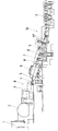
- the single drawing figure shows a schematic representation of a casting and rolling plant according to the invention. It consists of the melting furnace 1, the holding furnace 2, the trough 3, the tundish 4, the spout 5 of which protrudes into the area of the strip casting mold 6, the driver 7, the edge processing device 8 and the deformation frame 9.
- the melt in the melting furnace 1 and also in the holding furnace 2 is covered with charcoal to avoid oxygen absorption.
- the invention also provides for the melting furnace 1, the holding furnace 2, the casting trough 3 and the casting trough 4 to be housed and these units to be operated in a protective gas atmosphere.
- the housing is marked with H. All facilities are as tight as possible and - contrary to the usual gas heating - are inductively heated.
- the Nitrogen is preferably blown in the direction of material flow and flows towards the tundish, where it emerges together with the molten copper.
- the nitrogen flowing out of the tundish 4 protects the inlet area of the belt casting mold 6 against oxygen absorption due to its specific weight against air.
- mudguard constructions on the side can cause the nitrogen to remain in this area for a longer period of time and thus offer reliable protection against oxygen.
- the housings continue behind the belt casting mold 6; they include driver 7, edge processing device 8 and deformation stand 9 and possibly also the bending area 10. Following the deformation stand 9, the ingot in the turning area 10 is diverted from the casting direction into the horizontal, as is in accordance with the teaching of the invention.
- the system works as follows: The copper melt located in the melting furnace 1 is temporarily stored in the holding furnace 2 and passed via the trough 3 into the tundish 4. All units are sealed in a housing H, a protective gas atmosphere is created inside the housing H. From the tundish 4, through which nitrogen flows, the copper melt reaches the strip casting mold, in which a copper ingot is poured between the strip-shaped mold sides, which leaves the strip casting mold 6 in the casting direction after solidification.
- the copper bar which has a temperature of 980 to 1000 ° C., is driven into the Edge processing device 8, a milling machine, introduced where the edges of the billet are chamfered.
- the copper bar prepared in this way is then introduced into the forming frame.
- the construction of the deformation stand must have features that are inherently unusual in roughing stands in copper wire systems.
- the tip of the copper bar, on which the starting piece is still located, must be able to pass through the deformation frame 9 without deformation. Therefore, the rollers of the deformation stand 9 are first opened. When the desired strand speed is reached, the rolls are automatically closed until the preselected reduction is reached. For this purpose it is necessary that the speed of the rolls is determined and regulated depending on the respective deformation. This can be achieved by measuring the speed and current consumption of the driver 7.
- a reduction in the stitch of approx. 35% takes place in the deformation stand 9.
- the reduced copper ingot in the bending area 10 of the installation is moved horizontally on a roller table and reduced to wire in further rolling stands of the continuous rolling mill 11. This copper wire thus produced is bundled at the end (not shown) of the casting and rolling system.
Landscapes
- Engineering & Computer Science (AREA)
- Mechanical Engineering (AREA)
- Metal Rolling (AREA)
- Continuous Casting (AREA)
- Manufacture And Refinement Of Metals (AREA)
Abstract
Description
- Die Erfindung betrifft ein Verfahren und eine Vorrichtung zur Durchführung des Verfahrens zum Herstellen von Walzgut aus sauerstofffreiem Kupfer, insbesondere Draht in einer Gießwalzanlage, bestehend aus Erschmelzungsanlage, einer Gießanlage mit geneigt angeordneter mitlaufender Kokille sowie einem nachgeordneten kontinuierlichen Walzwerk.
- Zur Herstellung von Kupferdraht werden seit ca. 25 Jahren Anlagen gebaut, die in kontinuierlichem Fluß aus der flüssigen Schmelze über eine Gießmaschine mit mitlaufenden Kokillen und über ein kontinuierliches Walzwerk mit nachgeordneter Draht-Entzunderungsstrecke Kupferdraht erzeugen. Dieser Kupferdraht wird am Ende der Anlage zu Ringen von bis zu 10 Tonnen aufgewickelt.
- Bei der Erschmelzung, dem Vergießen und dem anschließenden Walzen nimmt der Barren bzw. der Kupferdraht Sauerstoff auf der für manche Zwecke unschädlich ist, jedoch für viele Verwendungszwecke, insbesondere für den Einsatz in der Elektronik sich schädlich auswirkt. Für diese besonderen Verwendungszwecke ist es unumgänglich, den Sauerstoffgehalt im Kupferdraht zu reduzieren oder auf Null zu bekommen. Die vorliegende Patentanmeldung hat zum Ziel, ein Verfahren und eine Vorrichtung zur Durchführung des Verfahrens zu schaffen, mit der es möglich wird, sauerstofffreien Kupferdraht in-line in einer gattungsgemäßen Gießwalzanlage zu erzeugen.
- Grundlage der Erfindung ist die Erkenntnis, daß die in der Fachwelt bekannte Erscheinung der Wasserstoffkrankheit bei sauerstofffreiem Kupfer nicht relevant ist.
- Bei sauerstoffhaltigem Kupfer reagiert der Sauerstoff mit dem im Kupfer befindliche Wasserstoff in der Art, daß sich erhitzter Wasserdampf bildet. Dabei entstehen sehr hohe Drücke, die zu Rissen längs der Korngrenzen führen und zu Aufbrüchen und schließlich auch zum Zerbrechen eines gegossenen warmen Kupferbarrens führen können. In Verbindung mit den im Kupfer befindlichen Begleitelementen (Verunreinigungen), wird die Riß- bzw. Bruchgefahr, insbesondere beim Biegen des gegossenen warmen Barrens, noch erhöht.
- Auch in sauerstofffreiem Kupfer sind trotz Erschmelzen und Vergießen unter Schutzgas definierte Mengen Wasserstoff enthalten. Es muß jedoch verhindert werden, daß sich durch Vereinigung kleiner Wasserstoffblasen größere Wasserstoffblasen an den Korngrenzen bilden und zur Warmrissigkeit führen, insbesondere bei gleichzeitiger Biegung des warmen Kupferbarrens. Die Möglichkeit der Bildung unerwünschter größerer Wasserstoffblasen ist desto wahrscheinlicher, je mehr Zeit ab der Erstarrung des flüssigen Kupfers zur Verfügung steht.
- Zur Lösung dieses Problems wird durch die vorliegende Erfindung vorgeschlagen, daß der die Gießanlage geradlinig verlassende Barren in die Horizontale abgebogen wird, nachdem er in mindestens einem Verformungsstich reduziert wurde. Die Erfindung besteht also darin, durch Verformung des Kupferbarrens unmittelbar hinter der Kokille die Korngrößen des Kupfers zu verkleinern und dadurch zu verhindern, daß sich größere Wasserstoffblasen an den Korngrenzen bilden. Das feine Gefüge verhindert weitgehend das tiefe Eindringen des Wasserstoffes und stellt somit ein wirksames Mittel gegen die Riss- und Bruchempfindlichkeit des Kupferbarrens dar.
- Nach einem weiteren Vorschlag der Erfindung ist vorgesehen, daß der Verformungsstich des Barrens sowie der Schmelz- und Gießvorgang in Schutzgas-Atmosphäre stattfinden, um die Sauerstoffaufnahme des sauerstofffrei erschmolzenen Kupfers während der einzelnen Verfahrensschritte möglichst zu verhindern.
- Vorzugsweise wird der erste Verformungsstich dicht hinter der Gießanlage durchgeführt. Das Abbiegen des Kupferbarrens nach dem ersten oder gegebenenfalls mehreren Reduzierstichen in Schutzgasatmosphäre ist nach der verkleinerten Korngröße unschädlich und führt nicht mehr zu den bislang nicht zu verhindernden Rissen.
- Es hat sich gezeigt, daß besonders günstige Ergebnisse dann erzielt werden, wenn die Reduktion im ersten Verformungsstich zwischen 10 und 50 Prozent, vorzugsweise 35 Prozent beträgt.
- Eine Gießwalzanlage zur Durchführung des erfindungsgemäßen Verfahrens ist gekennzeichnet durch die Anordnung mindestens eines Verformungsgerüstes hinter der Bandgießkokille, wobei die Walzachse des Verformungsgerüstes achsgleich mit der Mittellängsachse der Bandgießkokille ist und der Bereich zwischen Erschmelzungsofen und Bandgießkokille sowie zwischen Bandgießkokille und dem bzw. den ersten Verformungsgerüst(en) unter einer Einhausung angeordnet ist.
- Die nahe zur Gießmaschine angeordnete Verformungseinheit ist somit in gleicher Neigung wie die Gießanlage angeordnet, wobei gegebenenfalls weitere Einrichtungen zur Barrenvorbereitung (Kantenfräseinrichtung, Treiber etc.) zwischen der Gießanlage und dem ersten Verformungsgerüst vorgesehen sein können.
- Als besonders vorteilhaft wird angesehen, daß auf der erfindungsgemäßen Anlage sowohl sauerstofffreies wie auch sauerstoffhaltiges Kupfer verarbeitet werden können.
- Ein Ausführungsbeispiel der Erfindung ist in der Zeichnung dargestellt und wird nachfolgend beschrieben:
Die einzige Zeichnungsfigur zeigt in schematischer Darstellung eine Gießwalzanlage nach der Erfindung. Sie besteht aus dem Erschmelzungsofen 1, dem Warmhalteofen 2, der Gießrinne 3, der Gießwanne 4, deren Gießschnauze 5 in den Bereich der Bandgießkokille 6 ragt, dem Treiber 7, dem Kantenbearbeitungsgerät 8 und dem Verformungsgerüst 9. - Bekanntlich wird zur Vermeidung der Sauerstoffaufnahme die Schmelze im Erschmelzungsofen 1 wie auch im Warmhalteofen 2 mit Holzkohle abgedeckt. Die Erfindung sieht darüber hinaus vor, den Schmelzofen 1, den Warmhalteofen 2, die Gießrinne 3 und die Gießwanne 4 einzuhausen und diese Aggregate in einer Schutzgas-Atmosphäre zu betreiben. Die Einhausung ist mit H bezeichnet. Alle Einrichtungen sind möglichst dicht und - entgegen sonst üblicher Gasbeheizung - induktiv beheizt. Der Stickstoff wird vorzugsweise in Materiallaufrichtung eingeblasen und strömt in Richtung Gießwanne, wo er zusammen mit dem geschmolzenen Kupfer austritt.
- Der aus der Gießwanne 4 ausströmende Stickstoff schützt aufgrund seines spezifischen Gewichtes gegenüber Luft den Einlaufbereich der Bandgießkokille 6 vor Sauerstoffaufnahme. Zusätzlich können seitlich angeordnete Schutzblechkonstruktionen bewirken, daß der Stickstoff in diesem Bereich eine längere Verweilzeit hat und somit sicher Schutz vor Sauerstoff bietet.
- Wenn auch der in der Bandgießkokille 6 erstarrte Strang nicht mehr der Gefahr der Sauerstoffaufnahme im Stranginneren ausgesetzt ist, so muß jedoch eine Sauerstoffverbindung mit der walzwarmen Strangoberfläche möglichst vermieden werden. Zu diesem Zweck setzen sich die Einhausungen hinter der Bandgießkokille 6 fort; sie umfassen Treiber 7, Kantenbearbeitungsgerät 8 und Verformungsgerüst 9 sowie ggf. auch den Abbiegebereich 10. Im Anschluß an das Verformungsgerüst 9 wird der Barren im Abbiegebereich 10 aus der Gießrichtung in die Horizontale umgeleitet, wie es der Lehre der Erfindung entspricht.
- Die Anlage arbeitet wie folgt: Die im Erschmelzungsofen 1 befindliche Kupferschmelze wird im Warmhalteofen 2 zwischengespeichert und über die Gießrinne 3 in die Gießwanne 4 geleitet. Alle Aggregate sind in einer Einhausung H abgeschlossen, im Inneren der Einhausung H ist eine Schutzgas- Atmosphäre geschaffen. Von der Gießwanne 4, die von Stickstoff durchströmt ist, gelangt die Kupferschmelze in die Bandgießkokille, in der zwischen den bandförmigen Kokillenseiten ein Kupferbarren gegossen wird, der nach Erstarrung die Bandgießkokille 6 in Gießrichtung verläßt. Der eine Temperatur von 980 bis 1000° C aufweisende Kupferbarren wird mit Hilfe des Treibers 7 in das Kantenbearbeitungsgerät 8, eine Fräsmaschine, eingeführt, wo die Kanten des Barrens abgeschrägt werden. Im Anschluß daran wird der so vorbereitete Kupferbarren in das Verformungsgerüst eingeführt.
- Durch den verfahrensbedingten geringen Abstand zwischen Bandgießkokille 6 und dem Verformungsgerüst 9 muß die Konstruktion des Verformungsgerüstes Merkmale aufweisen, die an sich bei Vorwalzgerüsten in Kupferdrahtanlagen unüblich sind. So muß die Spitze des Kupferbarrens, an der sich noch das Anfahrstück befindet, ohne Verformung das Verformungsgerüst 9 passieren können. Deshalb sind die Walzen des Verformungsgerüstes 9 zunächst aufgefahren. Bei Erreichen der gewünschten Stranggeschwindigkeit werden die Walzen automatisch zugefahren, bis die vorgewählte Reduktion erreicht ist. Zu diesem Zweck ist es erforderlich, daß die Geschwindigkeit der Walzen in Abhängigkeit von der jeweiligen Verformung bestimmt und geregelt wird. Dies läßt sich durch Messen von Geschwindigkeit und Stromaufnahme des Treibers 7 erreichen.
- Im Verformungsgerüst 9 erfolgt eine Stichabnahme von ca. 35 %. Nach verlassen des Verformungsgerüstes 9 wird der reduzierte Kupferbarren im Abbiegebereich 10 der Anlage auf einem Rollgang in die Horizontale umgeführt und in weiteren Walzgerüsten der kontinuierlichen Walzstraße 11 zu Draht reduziert. Dieser so erzeugte Kupferdraht wird am (nicht dargestellten Ende) der Gießwalzanlage zu Bunden gelegt.
Claims (5)
- Verfahren zum Herstellen von Walzgut aus sauerstofffreiem Kupfer, insbesondere Draht in einer Gießwalzanlage, bestehend aus Erschmelzungsanlage, einer Bandgießkokille sowie einem nachgeordneten kontinuierlichen Walzwerk,
dadurch gekennzeichnet,
daß der die Gießanlage geradlinig verlassende Barren in die Horizontale abgebogen wird, nachdem er in mindestens einem Verformungsstich reduziert wurde. - Verfahren nach Anspruch 2,
dadurch gekennzeichnet,
daß der Verformungsstich des Barrens und/oder der Schmelz- und Gießvorgang in Schutzgas-Atmosphäre stattfinden. - Verfahren nach Anspruch 2,
dadurch gekennzeichnet,
daß der erste Verformungsstich dicht hinter der Gießanlage durchgeführt wird. - Verfahren nach Anspruch 1 bis 3,
dadurch gekennzeichnet,
daß die Reduktion im ersten Verformungsstich zwischen 10 und 50 Prozent, vorzugsweise 35 Prozent beträgt. - Gießwalzanlage zur Durchführung des Verfahrens nach Anspruch 1 bis 4,
gekennzeichnet durch die Anordnung mindestens eines Verformungsgerüstes (9) hinter der Bandgießkokille (6), wobei die Walzachse des Verformungsgerüstes (9) achsgleich mit der Mittellängsachse der Bandgießkokille (6) ist und der Bereich zwischen Erschmelzungsofen (1) und Bandgießkokille (6) sowie zwischen Bandgießkokille (6) und den bzw. dem ersten Verformungsgerüst(en) (9) unter einer Einhausung (H) angeordnet ist.
Applications Claiming Priority (2)
| Application Number | Priority Date | Filing Date | Title |
|---|---|---|---|
| DE4136085 | 1991-10-30 | ||
| DE4136085A DE4136085C2 (de) | 1991-10-30 | 1991-10-30 | Verfahren zum herstellen von sauerstoffreiem kupferdraht |
Publications (2)
| Publication Number | Publication Date |
|---|---|
| EP0542382A1 true EP0542382A1 (de) | 1993-05-19 |
| EP0542382B1 EP0542382B1 (de) | 1994-11-02 |
Family
ID=6443923
Family Applications (1)
| Application Number | Title | Priority Date | Filing Date |
|---|---|---|---|
| EP92250020A Expired - Lifetime EP0542382B1 (de) | 1991-10-30 | 1992-01-27 | Verfahren zum Herstellen von Walzgut aus sauerstofffreiem Kupfer |
Country Status (6)
| Country | Link |
|---|---|
| US (1) | US5366001A (de) |
| EP (1) | EP0542382B1 (de) |
| JP (1) | JP3244546B2 (de) |
| AU (1) | AU663528B2 (de) |
| DE (2) | DE4136085C2 (de) |
| ES (1) | ES2063564T3 (de) |
Cited By (1)
| Publication number | Priority date | Publication date | Assignee | Title |
|---|---|---|---|---|
| CN101224544B (zh) * | 2008-01-30 | 2010-06-02 | 江阴华电新材料有限公司 | 高强、高导引线框架铜合金带材的生产方法 |
Families Citing this family (16)
| Publication number | Priority date | Publication date | Assignee | Title |
|---|---|---|---|---|
| US5240494A (en) * | 1991-04-25 | 1993-08-31 | Asarco Incorporated | Method for melting copper |
| FR2727338A1 (fr) * | 1994-11-30 | 1996-05-31 | Usinor Sacilor | Dispositif de coulee continue entre cylindres a capotage d'inertage |
| FR2732627B1 (fr) * | 1995-04-07 | 1997-04-30 | Usinor Sacilor | Procede et dispositif de reglage du bombe des cylindres d'une installation de coulee de bandes metalliques |
| US6531039B2 (en) | 2001-02-21 | 2003-03-11 | Nikko Materials Usa, Inc. | Anode for plating a semiconductor wafer |
| DE10112621A1 (de) | 2001-03-14 | 2002-09-19 | Km Europa Metal Ag | Anordnung zum Abgießen einer aus einer Kupferlegierung bestehenden Gießschmelze |
| US20070227688A1 (en) * | 2004-06-15 | 2007-10-04 | Tosoh Smd, Inc. | Continuous Casting of Copper to Form Sputter Targets |
| US20060124271A1 (en) * | 2004-12-13 | 2006-06-15 | Mark Schlichting | Method of controlling the formation of crocodile skin surface roughness on thin cast strip |
| US7891407B2 (en) * | 2004-12-13 | 2011-02-22 | Nucor Corporation | Method and apparatus for localized control of heat flux in thin cast strip |
| CN100491001C (zh) * | 2005-09-09 | 2009-05-27 | 江苏兴荣高新科技股份有限公司 | 一种制造铜及铜合金带材的铸轧加工方法 |
| CN1307015C (zh) * | 2005-10-08 | 2007-03-28 | 刘瑞 | 一种无氧铜带坯生产装置 |
| JP4934438B2 (ja) * | 2007-01-17 | 2012-05-16 | 古河電気工業株式会社 | 無酸素銅線または銅合金線の製造方法およびその装置 |
| CN102500615B (zh) * | 2011-10-21 | 2014-08-13 | 厦门虹鹭钨钼工业有限公司 | 一种制造钨铜合金棒丝材的方法 |
| CN103921071B (zh) * | 2014-04-16 | 2016-04-20 | 黄学志 | 无氧铜排生产工艺 |
| CN114570900B (zh) * | 2022-03-03 | 2024-02-02 | 大连交通大学 | 一种铜及铜合金连续铸挤成形的装置及方法 |
| KR102589057B1 (ko) * | 2022-05-10 | 2023-10-12 | 엘에스전선 주식회사 | 무산소동 또는 무산소동 합금의 제조 방법 및 장치 |
| TWI843160B (zh) * | 2022-07-27 | 2024-05-21 | 大展電線電纜股份有限公司 | 無氧硬銅條與二極體元件之製作方法 |
Citations (4)
| Publication number | Priority date | Publication date | Assignee | Title |
|---|---|---|---|---|
| US3257835A (en) * | 1964-11-12 | 1966-06-28 | Southwire Co | Method of hot forming metal |
| DE1935736A1 (de) * | 1968-07-15 | 1970-07-02 | Metallurgie Hoboken | Verfahren und Vorrichtung zur kontinuierlichen Herstellung von Kupfer |
| US4290823A (en) * | 1973-10-22 | 1981-09-22 | Metallurgie Hoboken-Overpelt | Manufacture of copper wire rod |
| DE3036595A1 (de) * | 1980-09-27 | 1982-05-13 | Willi-Friedrich 3384 Liebenburg Oppermann | Verfahren zur gemeinsamen fertigung von baendern, profilen und draehten aus metallen in einer linie |
Family Cites Families (6)
| Publication number | Priority date | Publication date | Assignee | Title |
|---|---|---|---|---|
| US2264289A (en) * | 1939-08-22 | 1941-12-02 | American Smelting Refining | Process and apparatus for casting metal |
| US3089209A (en) * | 1960-01-06 | 1963-05-14 | American Smelting Refining | Method for continuous casting of metal |
| CA1106633A (en) * | 1977-10-05 | 1981-08-11 | Clovis Labrecque | Hub cap lock device |
| JPS58360A (ja) * | 1981-04-20 | 1983-01-05 | ヘイズレツト・ストリツプ・キヤステイング・コ−ポレ−シヨン | 陽極製造用二重ベルト鋳造機より退去した後の新しく鋳造された銅製品の酸化を防止する方法および装置 |
| JPS63171255A (ja) * | 1987-01-09 | 1988-07-15 | Sumitomo Metal Ind Ltd | 未凝固圧延方法 |
| US4754803A (en) * | 1987-02-02 | 1988-07-05 | Phelps Dodge Industries, Inc. | Manufacturing copper rod by casting, hot rolling and chemically shaving and pickling |
-
1991
- 1991-10-30 DE DE4136085A patent/DE4136085C2/de not_active Expired - Fee Related
-
1992
- 1992-01-27 EP EP92250020A patent/EP0542382B1/de not_active Expired - Lifetime
- 1992-01-27 ES ES92250020T patent/ES2063564T3/es not_active Expired - Lifetime
- 1992-01-27 DE DE59200731T patent/DE59200731D1/de not_active Expired - Fee Related
- 1992-10-27 JP JP31125392A patent/JP3244546B2/ja not_active Expired - Fee Related
- 1992-10-28 AU AU27387/92A patent/AU663528B2/en not_active Ceased
- 1992-10-30 US US07/969,884 patent/US5366001A/en not_active Expired - Lifetime
Patent Citations (4)
| Publication number | Priority date | Publication date | Assignee | Title |
|---|---|---|---|---|
| US3257835A (en) * | 1964-11-12 | 1966-06-28 | Southwire Co | Method of hot forming metal |
| DE1935736A1 (de) * | 1968-07-15 | 1970-07-02 | Metallurgie Hoboken | Verfahren und Vorrichtung zur kontinuierlichen Herstellung von Kupfer |
| US4290823A (en) * | 1973-10-22 | 1981-09-22 | Metallurgie Hoboken-Overpelt | Manufacture of copper wire rod |
| DE3036595A1 (de) * | 1980-09-27 | 1982-05-13 | Willi-Friedrich 3384 Liebenburg Oppermann | Verfahren zur gemeinsamen fertigung von baendern, profilen und draehten aus metallen in einer linie |
Non-Patent Citations (2)
| Title |
|---|
| DATABASE WPI Section Ch, Week 7405, Derwent Publications Ltd., London, GB; Class M22, AN 74-08825V(05) & SU-A-382 460 (HEAVY NON-FERROUS METALS) 27. Juli 1973 * |
| DATABASE WPI Section Ch, Week 7435, Derwent Publications Ltd., London, GB; Class M22, AN 74-62485V(35) & SU-A-404 549 (HEAVY NONFERROUS MET BUR) 10. April 1974 * |
Cited By (1)
| Publication number | Priority date | Publication date | Assignee | Title |
|---|---|---|---|---|
| CN101224544B (zh) * | 2008-01-30 | 2010-06-02 | 江阴华电新材料有限公司 | 高强、高导引线框架铜合金带材的生产方法 |
Also Published As
| Publication number | Publication date |
|---|---|
| DE4136085C2 (de) | 1993-11-04 |
| EP0542382B1 (de) | 1994-11-02 |
| JPH06106205A (ja) | 1994-04-19 |
| US5366001A (en) | 1994-11-22 |
| AU2738792A (en) | 1993-05-06 |
| DE59200731D1 (de) | 1994-12-08 |
| JP3244546B2 (ja) | 2002-01-07 |
| DE4136085A1 (de) | 1993-05-06 |
| AU663528B2 (en) | 1995-10-12 |
| ES2063564T3 (es) | 1995-01-01 |
Similar Documents
| Publication | Publication Date | Title |
|---|---|---|
| EP0542382B1 (de) | Verfahren zum Herstellen von Walzgut aus sauerstofffreiem Kupfer | |
| DE69604825T2 (de) | Verfahren und vorrichtung zur herstellung von verformbarem stahl | |
| DE2252722A1 (de) | Verfahren und vorrichtung zum direkten kuehlen einer kontinuierlich gewalzten stange | |
| DE2837432C2 (de) | Verfahren zum Stranggießen einer amorphen Legierung mittels Gießwalzen | |
| EP1181997A1 (de) | Verfahren und Vorrichtung zum kontinuierlichen Giessen von Stahlband aus Stahlschmelze | |
| DE102010050647A1 (de) | Anlage und Verfahren zum Gießen und Walzen von Metall | |
| DE3330810C2 (de) | Vorrichtung und Verfahren zum Stranggießen von Metall | |
| DE2163928B2 (de) | StranggieBverfahren sowie Vorrichtung zur Durchführung des Verfahrens | |
| DE2420347C3 (de) | Vorrichtung zur Herstellung von Kupferdraht | |
| DE3440236C2 (de) | ||
| DE68907644T2 (de) | Verfahren zur Kühlung eines metallischen Stranggussproduktes. | |
| DE3002347C2 (de) | Verfahren zum kontinuierlichen Gießen von Metall | |
| DE2853868C2 (de) | Verfahren zum Stranggießen von Stahl sowie dementsprechend hergestellter Stahlstrang | |
| DE2602339C2 (de) | Verfahren zum Stranggießen einer Aluminiumlegierung | |
| DE3048711A1 (de) | Verfahren zum kuehlen von straengen beim stranggiessen von stahl | |
| DE830387C (de) | Verfahren und Vorrichtung zum stetigen Giessen eines Metallstranges | |
| EP0152626B1 (de) | Verfahren und Einrichtung zum Erzeugen von dünnen Metallsträngen aus Metallschmelze, insbesondere von Stahlsträngen | |
| DE2557095A1 (de) | Einrichtungen fuer kontinuierliches giessen von aluminium und dessen legierung | |
| DE2727055A1 (de) | Verfahren zum kontinuierlichen herstellen eines kupferstranges | |
| EP0166718B1 (de) | Verfahren und Vorrichtung zum Stranggiessen von metallischen Schmelzen | |
| DE3306372A1 (de) | Verfahren zur herstellung von stahlblechen oder -platten | |
| DE2951911A1 (de) | Verfahren zur herstellung eines verguetbaren, in der waerme verformten produktes aus einer aluminiumlegierung | |
| DE1508884A1 (de) | Vorrichtung zum Stranggiessen,insbesondere von Metallen | |
| DE10025080A1 (de) | Verfahren zum Herstellen von Metallband | |
| DE3011124A1 (de) | Kontinuierliches herstellungsverfahren von kupferlegierungsdraehten |
Legal Events
| Date | Code | Title | Description |
|---|---|---|---|
| PUAI | Public reference made under article 153(3) epc to a published international application that has entered the european phase |
Free format text: ORIGINAL CODE: 0009012 |
|
| AK | Designated contracting states |
Kind code of ref document: A1 Designated state(s): BE DE ES FR GB GR IT |
|
| 17P | Request for examination filed |
Effective date: 19930525 |
|
| 17Q | First examination report despatched |
Effective date: 19931028 |
|
| GRAA | (expected) grant |
Free format text: ORIGINAL CODE: 0009210 |
|
| ITF | It: translation for a ep patent filed | ||
| AK | Designated contracting states |
Kind code of ref document: B1 Designated state(s): BE DE ES FR GB GR IT |
|
| ET | Fr: translation filed | ||
| REF | Corresponds to: |
Ref document number: 59200731 Country of ref document: DE Date of ref document: 19941208 |
|
| REG | Reference to a national code |
Ref country code: ES Ref legal event code: FG2A Ref document number: 2063564 Country of ref document: ES Kind code of ref document: T3 |
|
| REG | Reference to a national code |
Ref country code: GR Ref legal event code: FG4A Free format text: 3014189 |
|
| GBT | Gb: translation of ep patent filed (gb section 77(6)(a)/1977) |
Effective date: 19950117 |
|
| PLBE | No opposition filed within time limit |
Free format text: ORIGINAL CODE: 0009261 |
|
| 26N | No opposition filed | ||
| REG | Reference to a national code |
Ref country code: GB Ref legal event code: IF02 |
|
| PGFP | Annual fee paid to national office [announced via postgrant information from national office to epo] |
Ref country code: DE Payment date: 20070110 Year of fee payment: 16 |
|
| PGFP | Annual fee paid to national office [announced via postgrant information from national office to epo] |
Ref country code: GB Payment date: 20070119 Year of fee payment: 16 |
|
| PGFP | Annual fee paid to national office [announced via postgrant information from national office to epo] |
Ref country code: ES Payment date: 20070130 Year of fee payment: 16 |
|
| PGFP | Annual fee paid to national office [announced via postgrant information from national office to epo] |
Ref country code: BE Payment date: 20070223 Year of fee payment: 16 |
|
| PGFP | Annual fee paid to national office [announced via postgrant information from national office to epo] |
Ref country code: IT Payment date: 20070613 Year of fee payment: 16 |
|
| PGFP | Annual fee paid to national office [announced via postgrant information from national office to epo] |
Ref country code: GR Payment date: 20070123 Year of fee payment: 16 |
|
| PGFP | Annual fee paid to national office [announced via postgrant information from national office to epo] |
Ref country code: FR Payment date: 20070111 Year of fee payment: 16 |
|
| BERE | Be: lapsed |
Owner name: *MANNESMANN A.G. Effective date: 20080131 |
|
| GBPC | Gb: european patent ceased through non-payment of renewal fee |
Effective date: 20080127 |
|
| PG25 | Lapsed in a contracting state [announced via postgrant information from national office to epo] |
Ref country code: DE Free format text: LAPSE BECAUSE OF NON-PAYMENT OF DUE FEES Effective date: 20080801 |
|
| REG | Reference to a national code |
Ref country code: FR Ref legal event code: ST Effective date: 20081029 |
|
| PG25 | Lapsed in a contracting state [announced via postgrant information from national office to epo] |
Ref country code: GB Free format text: LAPSE BECAUSE OF NON-PAYMENT OF DUE FEES Effective date: 20080127 |
|
| PG25 | Lapsed in a contracting state [announced via postgrant information from national office to epo] |
Ref country code: BE Free format text: LAPSE BECAUSE OF NON-PAYMENT OF DUE FEES Effective date: 20080131 |
|
| REG | Reference to a national code |
Ref country code: ES Ref legal event code: FD2A Effective date: 20080128 |
|
| PG25 | Lapsed in a contracting state [announced via postgrant information from national office to epo] |
Ref country code: FR Free format text: LAPSE BECAUSE OF NON-PAYMENT OF DUE FEES Effective date: 20080131 |
|
| PG25 | Lapsed in a contracting state [announced via postgrant information from national office to epo] |
Ref country code: GR Free format text: LAPSE BECAUSE OF NON-PAYMENT OF DUE FEES Effective date: 20080804 |
|
| PG25 | Lapsed in a contracting state [announced via postgrant information from national office to epo] |
Ref country code: ES Free format text: LAPSE BECAUSE OF NON-PAYMENT OF DUE FEES Effective date: 20080128 |
|
| PG25 | Lapsed in a contracting state [announced via postgrant information from national office to epo] |
Ref country code: IT Free format text: LAPSE BECAUSE OF NON-PAYMENT OF DUE FEES Effective date: 20080127 |