EP0542405B1 - Coproduktion von reinem und ultrahochreinem flüchtigen Bestandteil eines Mehrkomponentenstroms - Google Patents
Coproduktion von reinem und ultrahochreinem flüchtigen Bestandteil eines Mehrkomponentenstroms Download PDFInfo
- Publication number
- EP0542405B1 EP0542405B1 EP92306309A EP92306309A EP0542405B1 EP 0542405 B1 EP0542405 B1 EP 0542405B1 EP 92306309 A EP92306309 A EP 92306309A EP 92306309 A EP92306309 A EP 92306309A EP 0542405 B1 EP0542405 B1 EP 0542405B1
- Authority
- EP
- European Patent Office
- Prior art keywords
- component
- distillation system
- fraction
- distillation
- volatile component
- Prior art date
- Legal status (The legal status is an assumption and is not a legal conclusion. Google has not performed a legal analysis and makes no representation as to the accuracy of the status listed.)
- Expired - Lifetime
Links
- IJGRMHOSHXDMSA-UHFFFAOYSA-N Atomic nitrogen Chemical compound N#N IJGRMHOSHXDMSA-UHFFFAOYSA-N 0.000 claims description 118
- 238000004821 distillation Methods 0.000 claims description 101
- 229910052757 nitrogen Inorganic materials 0.000 claims description 59
- 239000012535 impurity Substances 0.000 claims description 43
- 238000000034 method Methods 0.000 claims description 37
- 230000008569 process Effects 0.000 claims description 35
- 239000007788 liquid Substances 0.000 claims description 15
- 238000000926 separation method Methods 0.000 claims description 14
- QVGXLLKOCUKJST-UHFFFAOYSA-N atomic oxygen Chemical compound [O] QVGXLLKOCUKJST-UHFFFAOYSA-N 0.000 description 21
- 239000001301 oxygen Substances 0.000 description 21
- 229910052760 oxygen Inorganic materials 0.000 description 21
- XKRFYHLGVUSROY-UHFFFAOYSA-N Argon Chemical compound [Ar] XKRFYHLGVUSROY-UHFFFAOYSA-N 0.000 description 20
- 229910052786 argon Inorganic materials 0.000 description 10
- 239000002699 waste material Substances 0.000 description 7
- 238000010992 reflux Methods 0.000 description 6
- 238000005516 engineering process Methods 0.000 description 5
- 239000001307 helium Substances 0.000 description 4
- 229910052734 helium Inorganic materials 0.000 description 4
- SWQJXJOGLNCZEY-UHFFFAOYSA-N helium atom Chemical compound [He] SWQJXJOGLNCZEY-UHFFFAOYSA-N 0.000 description 4
- 239000001257 hydrogen Substances 0.000 description 4
- 229910052739 hydrogen Inorganic materials 0.000 description 4
- 238000004519 manufacturing process Methods 0.000 description 4
- 229910052754 neon Inorganic materials 0.000 description 4
- GKAOGPIIYCISHV-UHFFFAOYSA-N neon atom Chemical compound [Ne] GKAOGPIIYCISHV-UHFFFAOYSA-N 0.000 description 4
- MYMOFIZGZYHOMD-UHFFFAOYSA-N Dioxygen Chemical compound O=O MYMOFIZGZYHOMD-UHFFFAOYSA-N 0.000 description 3
- 150000002431 hydrogen Chemical class 0.000 description 3
- 230000006872 improvement Effects 0.000 description 3
- CURLTUGMZLYLDI-UHFFFAOYSA-N Carbon dioxide Chemical compound O=C=O CURLTUGMZLYLDI-UHFFFAOYSA-N 0.000 description 2
- 238000009833 condensation Methods 0.000 description 2
- 230000005494 condensation Effects 0.000 description 2
- 238000005194 fractionation Methods 0.000 description 2
- 239000007789 gas Substances 0.000 description 2
- VNWKTOKETHGBQD-UHFFFAOYSA-N methane Chemical compound C VNWKTOKETHGBQD-UHFFFAOYSA-N 0.000 description 2
- 230000004048 modification Effects 0.000 description 2
- 238000012986 modification Methods 0.000 description 2
- QJGQUHMNIGDVPM-UHFFFAOYSA-N nitrogen group Chemical group [N] QJGQUHMNIGDVPM-UHFFFAOYSA-N 0.000 description 2
- 238000011084 recovery Methods 0.000 description 2
- 239000006200 vaporizer Substances 0.000 description 2
- UFHFLCQGNIYNRP-UHFFFAOYSA-N Hydrogen Chemical compound [H][H] UFHFLCQGNIYNRP-UHFFFAOYSA-N 0.000 description 1
- 238000004458 analytical method Methods 0.000 description 1
- -1 argon (0.93%) Chemical compound 0.000 description 1
- 229910002092 carbon dioxide Inorganic materials 0.000 description 1
- 239000001569 carbon dioxide Substances 0.000 description 1
- 238000010586 diagram Methods 0.000 description 1
- 230000009977 dual effect Effects 0.000 description 1
- 230000000694 effects Effects 0.000 description 1
- 238000005265 energy consumption Methods 0.000 description 1
- 229930195733 hydrocarbon Natural products 0.000 description 1
- 150000002430 hydrocarbons Chemical class 0.000 description 1
- 239000002808 molecular sieve Substances 0.000 description 1
- 239000003345 natural gas Substances 0.000 description 1
- 230000009467 reduction Effects 0.000 description 1
- 239000004065 semiconductor Substances 0.000 description 1
- URGAHOPLAPQHLN-UHFFFAOYSA-N sodium aluminosilicate Chemical compound [Na+].[Al+3].[O-][Si]([O-])=O.[O-][Si]([O-])=O URGAHOPLAPQHLN-UHFFFAOYSA-N 0.000 description 1
- 238000009834 vaporization Methods 0.000 description 1
- 230000008016 vaporization Effects 0.000 description 1
- XLYOFNOQVPJJNP-UHFFFAOYSA-N water Substances O XLYOFNOQVPJJNP-UHFFFAOYSA-N 0.000 description 1
Images


Classifications
-
- F—MECHANICAL ENGINEERING; LIGHTING; HEATING; WEAPONS; BLASTING
- F25—REFRIGERATION OR COOLING; COMBINED HEATING AND REFRIGERATION SYSTEMS; HEAT PUMP SYSTEMS; MANUFACTURE OR STORAGE OF ICE; LIQUEFACTION SOLIDIFICATION OF GASES
- F25J—LIQUEFACTION, SOLIDIFICATION OR SEPARATION OF GASES OR GASEOUS OR LIQUEFIED GASEOUS MIXTURES BY PRESSURE AND COLD TREATMENT OR BY BRINGING THEM INTO THE SUPERCRITICAL STATE
- F25J3/00—Processes or apparatus for separating the constituents of gaseous or liquefied gaseous mixtures involving the use of liquefaction or solidification
- F25J3/02—Processes or apparatus for separating the constituents of gaseous or liquefied gaseous mixtures involving the use of liquefaction or solidification by rectification, i.e. by continuous interchange of heat and material between a vapour stream and a liquid stream
- F25J3/04—Processes or apparatus for separating the constituents of gaseous or liquefied gaseous mixtures involving the use of liquefaction or solidification by rectification, i.e. by continuous interchange of heat and material between a vapour stream and a liquid stream for air
- F25J3/044—Processes or apparatus for separating the constituents of gaseous or liquefied gaseous mixtures involving the use of liquefaction or solidification by rectification, i.e. by continuous interchange of heat and material between a vapour stream and a liquid stream for air using a single pressure main column system only
-
- B—PERFORMING OPERATIONS; TRANSPORTING
- B01—PHYSICAL OR CHEMICAL PROCESSES OR APPARATUS IN GENERAL
- B01D—SEPARATION
- B01D3/00—Distillation or related exchange processes in which liquids are contacted with gaseous media, e.g. stripping
- B01D3/14—Fractional distillation or use of a fractionation or rectification column
- B01D3/143—Fractional distillation or use of a fractionation or rectification column by two or more of a fractionation, separation or rectification step
- B01D3/146—Multiple effect distillation
-
- F—MECHANICAL ENGINEERING; LIGHTING; HEATING; WEAPONS; BLASTING
- F25—REFRIGERATION OR COOLING; COMBINED HEATING AND REFRIGERATION SYSTEMS; HEAT PUMP SYSTEMS; MANUFACTURE OR STORAGE OF ICE; LIQUEFACTION SOLIDIFICATION OF GASES
- F25J—LIQUEFACTION, SOLIDIFICATION OR SEPARATION OF GASES OR GASEOUS OR LIQUEFIED GASEOUS MIXTURES BY PRESSURE AND COLD TREATMENT OR BY BRINGING THEM INTO THE SUPERCRITICAL STATE
- F25J3/00—Processes or apparatus for separating the constituents of gaseous or liquefied gaseous mixtures involving the use of liquefaction or solidification
- F25J3/02—Processes or apparatus for separating the constituents of gaseous or liquefied gaseous mixtures involving the use of liquefaction or solidification by rectification, i.e. by continuous interchange of heat and material between a vapour stream and a liquid stream
- F25J3/0204—Processes or apparatus for separating the constituents of gaseous or liquefied gaseous mixtures involving the use of liquefaction or solidification by rectification, i.e. by continuous interchange of heat and material between a vapour stream and a liquid stream characterised by the feed stream
- F25J3/0209—Natural gas or substitute natural gas
-
- F—MECHANICAL ENGINEERING; LIGHTING; HEATING; WEAPONS; BLASTING
- F25—REFRIGERATION OR COOLING; COMBINED HEATING AND REFRIGERATION SYSTEMS; HEAT PUMP SYSTEMS; MANUFACTURE OR STORAGE OF ICE; LIQUEFACTION SOLIDIFICATION OF GASES
- F25J—LIQUEFACTION, SOLIDIFICATION OR SEPARATION OF GASES OR GASEOUS OR LIQUEFIED GASEOUS MIXTURES BY PRESSURE AND COLD TREATMENT OR BY BRINGING THEM INTO THE SUPERCRITICAL STATE
- F25J3/00—Processes or apparatus for separating the constituents of gaseous or liquefied gaseous mixtures involving the use of liquefaction or solidification
- F25J3/02—Processes or apparatus for separating the constituents of gaseous or liquefied gaseous mixtures involving the use of liquefaction or solidification by rectification, i.e. by continuous interchange of heat and material between a vapour stream and a liquid stream
- F25J3/0228—Processes or apparatus for separating the constituents of gaseous or liquefied gaseous mixtures involving the use of liquefaction or solidification by rectification, i.e. by continuous interchange of heat and material between a vapour stream and a liquid stream characterised by the separated product stream
- F25J3/0233—Processes or apparatus for separating the constituents of gaseous or liquefied gaseous mixtures involving the use of liquefaction or solidification by rectification, i.e. by continuous interchange of heat and material between a vapour stream and a liquid stream characterised by the separated product stream separation of CnHm with 1 carbon atom or more
-
- F—MECHANICAL ENGINEERING; LIGHTING; HEATING; WEAPONS; BLASTING
- F25—REFRIGERATION OR COOLING; COMBINED HEATING AND REFRIGERATION SYSTEMS; HEAT PUMP SYSTEMS; MANUFACTURE OR STORAGE OF ICE; LIQUEFACTION SOLIDIFICATION OF GASES
- F25J—LIQUEFACTION, SOLIDIFICATION OR SEPARATION OF GASES OR GASEOUS OR LIQUEFIED GASEOUS MIXTURES BY PRESSURE AND COLD TREATMENT OR BY BRINGING THEM INTO THE SUPERCRITICAL STATE
- F25J3/00—Processes or apparatus for separating the constituents of gaseous or liquefied gaseous mixtures involving the use of liquefaction or solidification
- F25J3/02—Processes or apparatus for separating the constituents of gaseous or liquefied gaseous mixtures involving the use of liquefaction or solidification by rectification, i.e. by continuous interchange of heat and material between a vapour stream and a liquid stream
- F25J3/0228—Processes or apparatus for separating the constituents of gaseous or liquefied gaseous mixtures involving the use of liquefaction or solidification by rectification, i.e. by continuous interchange of heat and material between a vapour stream and a liquid stream characterised by the separated product stream
- F25J3/0257—Processes or apparatus for separating the constituents of gaseous or liquefied gaseous mixtures involving the use of liquefaction or solidification by rectification, i.e. by continuous interchange of heat and material between a vapour stream and a liquid stream characterised by the separated product stream separation of nitrogen
-
- F—MECHANICAL ENGINEERING; LIGHTING; HEATING; WEAPONS; BLASTING
- F25—REFRIGERATION OR COOLING; COMBINED HEATING AND REFRIGERATION SYSTEMS; HEAT PUMP SYSTEMS; MANUFACTURE OR STORAGE OF ICE; LIQUEFACTION SOLIDIFICATION OF GASES
- F25J—LIQUEFACTION, SOLIDIFICATION OR SEPARATION OF GASES OR GASEOUS OR LIQUEFIED GASEOUS MIXTURES BY PRESSURE AND COLD TREATMENT OR BY BRINGING THEM INTO THE SUPERCRITICAL STATE
- F25J3/00—Processes or apparatus for separating the constituents of gaseous or liquefied gaseous mixtures involving the use of liquefaction or solidification
- F25J3/02—Processes or apparatus for separating the constituents of gaseous or liquefied gaseous mixtures involving the use of liquefaction or solidification by rectification, i.e. by continuous interchange of heat and material between a vapour stream and a liquid stream
- F25J3/04—Processes or apparatus for separating the constituents of gaseous or liquefied gaseous mixtures involving the use of liquefaction or solidification by rectification, i.e. by continuous interchange of heat and material between a vapour stream and a liquid stream for air
- F25J3/04248—Generation of cold for compensating heat leaks or liquid production, e.g. by Joule-Thompson expansion
- F25J3/04284—Generation of cold for compensating heat leaks or liquid production, e.g. by Joule-Thompson expansion using internal refrigeration by open-loop gas work expansion, e.g. of intermediate or oxygen enriched (waste-)streams
-
- F—MECHANICAL ENGINEERING; LIGHTING; HEATING; WEAPONS; BLASTING
- F25—REFRIGERATION OR COOLING; COMBINED HEATING AND REFRIGERATION SYSTEMS; HEAT PUMP SYSTEMS; MANUFACTURE OR STORAGE OF ICE; LIQUEFACTION SOLIDIFICATION OF GASES
- F25J—LIQUEFACTION, SOLIDIFICATION OR SEPARATION OF GASES OR GASEOUS OR LIQUEFIED GASEOUS MIXTURES BY PRESSURE AND COLD TREATMENT OR BY BRINGING THEM INTO THE SUPERCRITICAL STATE
- F25J3/00—Processes or apparatus for separating the constituents of gaseous or liquefied gaseous mixtures involving the use of liquefaction or solidification
- F25J3/02—Processes or apparatus for separating the constituents of gaseous or liquefied gaseous mixtures involving the use of liquefaction or solidification by rectification, i.e. by continuous interchange of heat and material between a vapour stream and a liquid stream
- F25J3/04—Processes or apparatus for separating the constituents of gaseous or liquefied gaseous mixtures involving the use of liquefaction or solidification by rectification, i.e. by continuous interchange of heat and material between a vapour stream and a liquid stream for air
- F25J3/04248—Generation of cold for compensating heat leaks or liquid production, e.g. by Joule-Thompson expansion
- F25J3/04284—Generation of cold for compensating heat leaks or liquid production, e.g. by Joule-Thompson expansion using internal refrigeration by open-loop gas work expansion, e.g. of intermediate or oxygen enriched (waste-)streams
- F25J3/04321—Generation of cold for compensating heat leaks or liquid production, e.g. by Joule-Thompson expansion using internal refrigeration by open-loop gas work expansion, e.g. of intermediate or oxygen enriched (waste-)streams of oxygen
-
- F—MECHANICAL ENGINEERING; LIGHTING; HEATING; WEAPONS; BLASTING
- F25—REFRIGERATION OR COOLING; COMBINED HEATING AND REFRIGERATION SYSTEMS; HEAT PUMP SYSTEMS; MANUFACTURE OR STORAGE OF ICE; LIQUEFACTION SOLIDIFICATION OF GASES
- F25J—LIQUEFACTION, SOLIDIFICATION OR SEPARATION OF GASES OR GASEOUS OR LIQUEFIED GASEOUS MIXTURES BY PRESSURE AND COLD TREATMENT OR BY BRINGING THEM INTO THE SUPERCRITICAL STATE
- F25J3/00—Processes or apparatus for separating the constituents of gaseous or liquefied gaseous mixtures involving the use of liquefaction or solidification
- F25J3/02—Processes or apparatus for separating the constituents of gaseous or liquefied gaseous mixtures involving the use of liquefaction or solidification by rectification, i.e. by continuous interchange of heat and material between a vapour stream and a liquid stream
- F25J3/04—Processes or apparatus for separating the constituents of gaseous or liquefied gaseous mixtures involving the use of liquefaction or solidification by rectification, i.e. by continuous interchange of heat and material between a vapour stream and a liquid stream for air
- F25J3/04248—Generation of cold for compensating heat leaks or liquid production, e.g. by Joule-Thompson expansion
- F25J3/04333—Generation of cold for compensating heat leaks or liquid production, e.g. by Joule-Thompson expansion using quasi-closed loop internal vapor compression refrigeration cycles, e.g. of intermediate or oxygen enriched (waste-)streams
- F25J3/04351—Generation of cold for compensating heat leaks or liquid production, e.g. by Joule-Thompson expansion using quasi-closed loop internal vapor compression refrigeration cycles, e.g. of intermediate or oxygen enriched (waste-)streams of nitrogen
-
- F—MECHANICAL ENGINEERING; LIGHTING; HEATING; WEAPONS; BLASTING
- F25—REFRIGERATION OR COOLING; COMBINED HEATING AND REFRIGERATION SYSTEMS; HEAT PUMP SYSTEMS; MANUFACTURE OR STORAGE OF ICE; LIQUEFACTION SOLIDIFICATION OF GASES
- F25J—LIQUEFACTION, SOLIDIFICATION OR SEPARATION OF GASES OR GASEOUS OR LIQUEFIED GASEOUS MIXTURES BY PRESSURE AND COLD TREATMENT OR BY BRINGING THEM INTO THE SUPERCRITICAL STATE
- F25J2200/00—Processes or apparatus using separation by rectification
- F25J2200/02—Processes or apparatus using separation by rectification in a single pressure main column system
-
- F—MECHANICAL ENGINEERING; LIGHTING; HEATING; WEAPONS; BLASTING
- F25—REFRIGERATION OR COOLING; COMBINED HEATING AND REFRIGERATION SYSTEMS; HEAT PUMP SYSTEMS; MANUFACTURE OR STORAGE OF ICE; LIQUEFACTION SOLIDIFICATION OF GASES
- F25J—LIQUEFACTION, SOLIDIFICATION OR SEPARATION OF GASES OR GASEOUS OR LIQUEFIED GASEOUS MIXTURES BY PRESSURE AND COLD TREATMENT OR BY BRINGING THEM INTO THE SUPERCRITICAL STATE
- F25J2200/00—Processes or apparatus using separation by rectification
- F25J2200/30—Processes or apparatus using separation by rectification using a side column in a single pressure column system
-
- F—MECHANICAL ENGINEERING; LIGHTING; HEATING; WEAPONS; BLASTING
- F25—REFRIGERATION OR COOLING; COMBINED HEATING AND REFRIGERATION SYSTEMS; HEAT PUMP SYSTEMS; MANUFACTURE OR STORAGE OF ICE; LIQUEFACTION SOLIDIFICATION OF GASES
- F25J—LIQUEFACTION, SOLIDIFICATION OR SEPARATION OF GASES OR GASEOUS OR LIQUEFIED GASEOUS MIXTURES BY PRESSURE AND COLD TREATMENT OR BY BRINGING THEM INTO THE SUPERCRITICAL STATE
- F25J2200/00—Processes or apparatus using separation by rectification
- F25J2200/50—Processes or apparatus using separation by rectification using multiple (re-)boiler-condensers at different heights of the column
-
- F—MECHANICAL ENGINEERING; LIGHTING; HEATING; WEAPONS; BLASTING
- F25—REFRIGERATION OR COOLING; COMBINED HEATING AND REFRIGERATION SYSTEMS; HEAT PUMP SYSTEMS; MANUFACTURE OR STORAGE OF ICE; LIQUEFACTION SOLIDIFICATION OF GASES
- F25J—LIQUEFACTION, SOLIDIFICATION OR SEPARATION OF GASES OR GASEOUS OR LIQUEFIED GASEOUS MIXTURES BY PRESSURE AND COLD TREATMENT OR BY BRINGING THEM INTO THE SUPERCRITICAL STATE
- F25J2200/00—Processes or apparatus using separation by rectification
- F25J2200/72—Refluxing the column with at least a part of the totally condensed overhead gas
-
- F—MECHANICAL ENGINEERING; LIGHTING; HEATING; WEAPONS; BLASTING
- F25—REFRIGERATION OR COOLING; COMBINED HEATING AND REFRIGERATION SYSTEMS; HEAT PUMP SYSTEMS; MANUFACTURE OR STORAGE OF ICE; LIQUEFACTION SOLIDIFICATION OF GASES
- F25J—LIQUEFACTION, SOLIDIFICATION OR SEPARATION OF GASES OR GASEOUS OR LIQUEFIED GASEOUS MIXTURES BY PRESSURE AND COLD TREATMENT OR BY BRINGING THEM INTO THE SUPERCRITICAL STATE
- F25J2200/00—Processes or apparatus using separation by rectification
- F25J2200/76—Refluxing the column with condensed overhead gas being cycled in a quasi-closed loop refrigeration cycle
-
- F—MECHANICAL ENGINEERING; LIGHTING; HEATING; WEAPONS; BLASTING
- F25—REFRIGERATION OR COOLING; COMBINED HEATING AND REFRIGERATION SYSTEMS; HEAT PUMP SYSTEMS; MANUFACTURE OR STORAGE OF ICE; LIQUEFACTION SOLIDIFICATION OF GASES
- F25J—LIQUEFACTION, SOLIDIFICATION OR SEPARATION OF GASES OR GASEOUS OR LIQUEFIED GASEOUS MIXTURES BY PRESSURE AND COLD TREATMENT OR BY BRINGING THEM INTO THE SUPERCRITICAL STATE
- F25J2200/00—Processes or apparatus using separation by rectification
- F25J2200/90—Details relating to column internals, e.g. structured packing, gas or liquid distribution
- F25J2200/94—Details relating to the withdrawal point
-
- F—MECHANICAL ENGINEERING; LIGHTING; HEATING; WEAPONS; BLASTING
- F25—REFRIGERATION OR COOLING; COMBINED HEATING AND REFRIGERATION SYSTEMS; HEAT PUMP SYSTEMS; MANUFACTURE OR STORAGE OF ICE; LIQUEFACTION SOLIDIFICATION OF GASES
- F25J—LIQUEFACTION, SOLIDIFICATION OR SEPARATION OF GASES OR GASEOUS OR LIQUEFIED GASEOUS MIXTURES BY PRESSURE AND COLD TREATMENT OR BY BRINGING THEM INTO THE SUPERCRITICAL STATE
- F25J2215/00—Processes characterised by the type or other details of the product stream
- F25J2215/42—Nitrogen or special cases, e.g. multiple or low purity N2
-
- F—MECHANICAL ENGINEERING; LIGHTING; HEATING; WEAPONS; BLASTING
- F25—REFRIGERATION OR COOLING; COMBINED HEATING AND REFRIGERATION SYSTEMS; HEAT PUMP SYSTEMS; MANUFACTURE OR STORAGE OF ICE; LIQUEFACTION SOLIDIFICATION OF GASES
- F25J—LIQUEFACTION, SOLIDIFICATION OR SEPARATION OF GASES OR GASEOUS OR LIQUEFIED GASEOUS MIXTURES BY PRESSURE AND COLD TREATMENT OR BY BRINGING THEM INTO THE SUPERCRITICAL STATE
- F25J2215/00—Processes characterised by the type or other details of the product stream
- F25J2215/42—Nitrogen or special cases, e.g. multiple or low purity N2
- F25J2215/44—Ultra high purity nitrogen, i.e. generally less than 1 ppb impurities
-
- F—MECHANICAL ENGINEERING; LIGHTING; HEATING; WEAPONS; BLASTING
- F25—REFRIGERATION OR COOLING; COMBINED HEATING AND REFRIGERATION SYSTEMS; HEAT PUMP SYSTEMS; MANUFACTURE OR STORAGE OF ICE; LIQUEFACTION SOLIDIFICATION OF GASES
- F25J—LIQUEFACTION, SOLIDIFICATION OR SEPARATION OF GASES OR GASEOUS OR LIQUEFIED GASEOUS MIXTURES BY PRESSURE AND COLD TREATMENT OR BY BRINGING THEM INTO THE SUPERCRITICAL STATE
- F25J2220/00—Processes or apparatus involving steps for the removal of impurities
- F25J2220/42—Separating low boiling, i.e. more volatile components from nitrogen, e.g. He, H2, Ne
-
- F—MECHANICAL ENGINEERING; LIGHTING; HEATING; WEAPONS; BLASTING
- F25—REFRIGERATION OR COOLING; COMBINED HEATING AND REFRIGERATION SYSTEMS; HEAT PUMP SYSTEMS; MANUFACTURE OR STORAGE OF ICE; LIQUEFACTION SOLIDIFICATION OF GASES
- F25J—LIQUEFACTION, SOLIDIFICATION OR SEPARATION OF GASES OR GASEOUS OR LIQUEFIED GASEOUS MIXTURES BY PRESSURE AND COLD TREATMENT OR BY BRINGING THEM INTO THE SUPERCRITICAL STATE
- F25J2240/00—Processes or apparatus involving steps for expanding of process streams
- F25J2240/02—Expansion of a process fluid in a work-extracting turbine (i.e. isentropic expansion), e.g. of the feed stream
- F25J2240/12—Expansion of a process fluid in a work-extracting turbine (i.e. isentropic expansion), e.g. of the feed stream the fluid being nitrogen
-
- F—MECHANICAL ENGINEERING; LIGHTING; HEATING; WEAPONS; BLASTING
- F25—REFRIGERATION OR COOLING; COMBINED HEATING AND REFRIGERATION SYSTEMS; HEAT PUMP SYSTEMS; MANUFACTURE OR STORAGE OF ICE; LIQUEFACTION SOLIDIFICATION OF GASES
- F25J—LIQUEFACTION, SOLIDIFICATION OR SEPARATION OF GASES OR GASEOUS OR LIQUEFIED GASEOUS MIXTURES BY PRESSURE AND COLD TREATMENT OR BY BRINGING THEM INTO THE SUPERCRITICAL STATE
- F25J2250/00—Details related to the use of reboiler-condensers
- F25J2250/20—Boiler-condenser with multiple exchanger cores in parallel or with multiple re-boiling or condensing streams
-
- F—MECHANICAL ENGINEERING; LIGHTING; HEATING; WEAPONS; BLASTING
- F25—REFRIGERATION OR COOLING; COMBINED HEATING AND REFRIGERATION SYSTEMS; HEAT PUMP SYSTEMS; MANUFACTURE OR STORAGE OF ICE; LIQUEFACTION SOLIDIFICATION OF GASES
- F25J—LIQUEFACTION, SOLIDIFICATION OR SEPARATION OF GASES OR GASEOUS OR LIQUEFIED GASEOUS MIXTURES BY PRESSURE AND COLD TREATMENT OR BY BRINGING THEM INTO THE SUPERCRITICAL STATE
- F25J2270/00—Refrigeration techniques used
- F25J2270/42—Quasi-closed internal or closed external nitrogen refrigeration cycle
Definitions
- This invention relates to the distillation separation of streams for the coproduction of a normal purity and ultra high purity volatile component in the gas stream.
- US-A-4,662,917 discloses a single column process for the production of nitrogen and oxygen.
- air is freed of its impurities and cooled to its dew point temperature and introduced into a single column for separation into its components.
- An oxygen-rich heavy stream is removed from the bottom of the column and removed as a product.
- a nitrogen-rich fraction is removed from the top of the column.
- a portion is condensed against oxygen-rich heavy stream in a boiler/con-denser wherein a portion is returned as reflux to the single column and a portion removed as product.
- US-A-4,824,453 discloses a process for air separation in which air is preliminarily separated in a first rectification stage to obtain a nitrogen-rich fraction and an oxygen-rich fraction. These two fractions are fed to a second rectification stage and separated into oxygen and nitrogen fractions.
- An argon-enriched fraction, containing essentially oxygen and argon, is removed from the second rectification state at an intermediate point and is separated in a raw argon column by rectification into an argon-rich fraction and a liquid fraction containing essentially oxygen. The liquid fraction is fed back into the second rectification state.
- Another fraction is removed from the raw argon column above the bottom thereof and is separated in a high-purity oxygen column to produce a high-purity oxygen fraction, and a lighter residual fraction.
- An additional nitrogen-rich fraction is removed from the head of the first rectification stage and separated in a high-purity nitrogen column producing a bottom liquid fraction, and a residual gas fraction.
- US-A-4,871,382 discloses a conventional dual column process for the separation of air into its components which includes a side arm column for the recovery of argon.
- air is introduced to a high pressure column wherein a nitrogen-rich fraction is generated at the top of the column and an oxygen-rich fraction is generated at the bottom of the column.
- a portion of the oxygen-rich fraction and nitrogen-rich overhead fraction is introduced to a low pressure column wherein further fractionation is effected.
- a nitrogen-rich overhead is recovered as product from the low pressure column and oxygen, either in liquid or gaseous form, is recovered from the bottom of the low pressure column.
- An argon stream is obtained by removing an argon-rich side stream from the low pressure column and fractionating in a side arm column wherein argon is removed as an overhead fraction and oxygen is removed as a bottom fraction.
- US-A-4,902,321 discloses a process for the production of ultra high purity nitrogen by the cryogenic distillation of an air stream. As in the above references, an oxygen-rich stream is generated at the bottom of a distillation column, and a nitrogen-rich stream is generated as an overhead in the column.
- US-A-5,049,173 discloses a process for producing ultra high purity oxygen from an air stream.
- an oxygen-rich bottoms fraction and a nitrogen-rich overhead fraction is produced from the distillation column.
- An oxygen-containing stream essentially free of heavy components is charged to a second fractionation column wherein the oxygen is stripped of volatile impurities and an ultra high purity liquid oxygen fraction is obtained.
- This invention relates to an improvement in a distillation separation of a multi-component stream comprising a major volatile component (A), a major heavy component (B), and lighter impurity (I) which has a higher volatility than component (A).
- component (A) is separated from component (B), and (A) is removed as an overhead fraction along with lighter impurity (I).
- a stream rich in component (B) is removed as a bottoms fraction and is substantially free of lighter impurity (I).
- the improvement for coproduction of a stream comprising component (A) of normal purity and containing small amounts of lighter impurity (I) and a stream of component (A) in ultra high purity which is substantially free of lighter impurity (I) is obtained through the following distillation sequence.
- a multi-component stream is fed to a first distillation column having an upper rectification zone for effecting enrichment of component (A) and removal therefrom as an overhead and a lower stripping zone for the enrichment of component (B) and removal therefrom as a bottoms fraction.
- a stream is withdrawn from the first distillation column at a point where the stream contains a substantial amount of component (A) and is substantially free of any lighter impurity (I).
- This stream then is introduced to a second distillation column having at least a rectification zone. Introduction is made at a point below such rectification zone wherein the volatile component (A) is enriched in the rectification zone and ultimately withdrawn as a fraction above the rectification zone.
- a bottoms fraction rich in component (B) is withdrawn at a point below the rectification zone.
- the stream from above the rectification zone of the second distillation column is of substantially higher purity than the overhead from the first distillation column.
- the invention provides a process for coproducing a volatile component of normal and higher purity from a multi-component feed stream comprising the volatile component, a heavier component and a lighter impurity having a higher volatility than said volatile component which comprises fractionally distilling said feed stream in a first distillation system having a rectification zone providing an overhead fraction enriched in the volatile component and a stripping zone providing a bottoms fraction enriched in the heavier component, and rectifying, in a second distillation system, a fraction obtained from said first distillation system to provide the volatile component at the higher purity, characterized in that said fraction rectified in the second distillation system is a stripped fraction of the first distillation system comprising the volatile and heavier components but is substantially free of the lighter impurity.
- the invention also provides a distillation apparatus for coproducing a volatile component of normal and higher purity from a multi-component stream comprising the volatile component, a heavier component and a lighter impurity having a higher volatility than said volatile component, said apparatus comprising: a first distillation system having a rectification zone providing an overhead fraction enriched in the volatile component and a stripping zone providing a bottoms fraction enriched in the heavier component; a second distillation system having a rectification zone for rectifying a fraction obtained from the first distillation system to provide the volatile component at the higher purity; and conduit means connecting said first and second distillation systems for introducing to the second distillation system said fraction to be rectified, characterized in that: said conduit means is connected to the first distillation system at a position whereby said fraction to be rectified comprises volatile and heavier components but is essentially free of the lighter impurity.
- the process described herein is particularly adapted for the coproduction of a volatile component (A) from a multi-component stream containing a heavy component (B) and at least one lighter impurity (I) which is of higher volatility than component (A).
- the multi-component stream will contain other components.
- Typical streams for separation include air where high purity and ultra high purity nitrogen are desired as a coproduct.
- the process is equally adapted for the production of hydrocarbons of variable purity.
- a multi-component stream comprising a volatile major component (A), and a heavy component (B) and at least one lighter impurity I is distilled.
- nitrogen is the volatile major component (A) with a concentration of 78.12%
- oxygen with a concentration of 20.95% is the predominant heavy component; however, other components heavier than nitrogen such as argon (0.93%), are typically present in a heavy component (B).
- the lighter impurities (I) which are more volatile than nitrogen and present in air are hydrogen (concentration up to 10 ppm), helium (5.3 ppm) and neon (18 ppm).
- the concentration of lighter impurities (I) can be much higher than ppm levels.
- the multi-component stream is fed via line 10 to distillation column 12 comprising a rectification section 14 and a stripping section 16.
- the feed is introduced intermediate the rectification and stripping section wherein the volatile component (A) and lighter impurity (I) are enriched and generated as a overhead which is removed via line 18.
- the overhead is condensed in condenser 20 and a portion of the condensate returned via line 22 as reflux to the top of distillation column 12.
- the remainder of the condensate is removed via line 24. It comprises component (A) in major portion contaminated with lighter impurities.
- a portion of stream 18 could be removed as gaseous product.
- nitrogen (component A) is produced at a purity greater than 99.5% and contains up to 50 ppm of lighter impurities (I) such as hydrogen, helium, and neon.
- the heavy component (B) in feed stream 10 is enriched in stripping section 16 and a liquid fraction rich in heavy components is withdrawn via line 26 from the bottom of distillation column 12. A portion of this liquid fraction is vaporized in boiler/condenser 28 and the vapor reintroduced for stripping at the bottom of stripping section 16. The balance of the liquid fraction rich in heavy component (B) is removed via line 30.
- the generation of an ultra high purity fraction of component (A) is effected by removing a stream 32 containing a substantial portion of component (A) which is contaminated with component (B), but essentially free of any lighter impurity (I) from distillation column 12.
- the concentration of the lighter impurity (I) in this stream is less than that required in the ultra high purity coproduct from the top of the auxiliary rectifying column 34.
- the combined concentration of these light impurities in this stream should be less than 3 ppb.
- the point of removal of the stream is from a suitable location of the stripping zone 16.
- the stream is removed via line 32 wherein it is introduced to an auxiliary rectifying column 34 having a rectification zone therein.
- the feed is purified wherein an ultra high purity product is generated within the top section of the rectification zone and an ultra high purity vapor removed via line 36.
- This vapor stream is at least partially condensed in boiler/condenser 38 and a portion of the condensate returned via line 40 as reflux for effecting stripping of the heavier component, i.e., component (B) from any stream.
- component (A) which is in ultra high purity, is removed via line 42.
- a portion of the ultra high purity vapor in line 36 may be removed to provide gaseous ultra high purity coproduct (A).
- the bottoms fraction which is rich in component (B) is removed from the bottom of auxiliary rectifying column 34 via line 44 and introduced to distillation column 12 at a suitable point in the stripping section 16 of column 12.
- component (A), e.g. nitrogen, with normal and ultra high purity is essentially the same and that the coproduction of component (A), e.g. nitrogen, in conventional and ultra high purity is achieved without effecting further condensation and vaporization of the respective streams as, for example, is apparent from the flow scheme in the '321 patent.
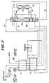
- Figure 2 represents an embodiment of the invention involving the cryogenic distillation of air wherein nitrogen of conventional purity and ultra high purity are obtained as products.
- the process achieves these results through a conventional waste expander cycle having a nitrogen recycle modified in accordance with the concepts described herein.
- the conventional waste expander cycle having a nitrogen recycle and producing normal purity nitrogen is described in US-A-4,400,188. More specifically in the modified process, air is introduced via line 100, compressed, cooled and water and carbon dioxide are adsorbed on a molecular sieve bed prior to introduction to a main heat exchanger series designated 102 and 104. Air is cooled close to its dew point temperature in heat exchanger systems 102 and 104 and then introduced via line 106 to a single column distillation system 108.
- a nitrogen rich fraction is generated as an overhead in the top of the column and an oxygen rich fraction is generated at the bottom of the column.
- a portion of the nitrogen rich vapor fraction is removed via line 110 and warmed against process streams in heat exchanger 104 and 102. Part of that stream is removed as normal purity product and a portion recompressed, cooled and condensed in boiler/condenser 112 in the bottom of distillation column 108. That condensed stream then is isenthalpically expanded and introduced to the top of the column for providing reflux to the column.
- Another portion of the nitrogen rich vapor is removed via line 114, condensed in boiler/condenser 116 and at least a portion of the condensate returned to the top of the column as reflux.
- the balance may be removed via line 118 as optional liquid nitrogen product of normal purity.
- Crude liquid oxygen from the bottom of distillation column 108 is conveyed via line 120 to the vaporizer side of boiler/condenser 116 and vaporized against the nitrogen rich vapor obtained from the top of the column.
- the vaporized crude liquid oxygen is removed from the vaporizer section via line 122, warmed, expanded, warmed again against process streams and removed as a waste product.
- Ultra high purity nitrogen is removed as a coproduct from this process by removing a stream containing nitrogen via line 124 from the stripping section of distillation column 108 at a point below the introduction of the feed air to the column.
- This stream is essentially free of lighter impurities, e.g. less than 5 ppm by volumes of highly volatile impurities such as hydrogen, helium and neon and preferably less than 5 ppb by volume.
- This stream is introduced to a second distillation column 126 having a rectification zone therein. The nitrogen containing stream is fed to column 126 and is freed of residual heavies producing an ultra high purity nitrogen product at the top of the column.
- a portion of the overhead from the top of distillation column 126 is conveyed via line 128 to boiler/condenser 116 and at least a portion of the condensed fraction returned as reflux to the top of distillation column 126.
- the balance of the ultra high purity nitrogen product is removed via line 130 wherein it is warmed against process streams and removed as a product via line 132. If desired, a portion of the condensed stream 128 from the boiler/condenser 116 could be produced as a liquid nitrogen product of ultra high purity.
- the oxygen component in the stream introduced to distillation column 126 is removed as a liquid from the bottom of that column via line 134. That fraction is returned to the stripping section of distillation column 108.
- Figure 2 thus illustrates a modification of a conventional waste expander nitrogen recycle process for the separation of air wherein ultra high purity and normal purity nitrogen are produced as coproducts.
- the ultra high purity nitrogen is produced without a reduction in pressure from that of standard product nitrogen and essentially no additional energy is provided to the system other than what is present in the process streams.
- Figure 2 shows an application of the invention to a nitrogen generator having a waste expander and nitrogen recycle.
- the concept is applicable to other nitrogen generators with a stripping section.
- Other examples of single column nitrogen generators with a stripping section are described in US-A-4,464,188; 4,662,916-918; 4,594,085 and 4,867,773.
- boilup at the bottom of the distillation column is provided by either condensing a nitrogen stream or an air stream or a combination thereof.
- the invention is also applicable to double column nitrogen generating processes well known in the art. Examples of the double column nitrogen generators can be found in GB-A-1,215,377; US-A-4,617,026 and US-A-5,006,137.
- the stripping section of the lower pressure column also sometimes referred to as upper column or medium pressure column
- FIG 3 shows an application of the invention wherein a stripping section is incorporated above the rectification zone in second distillation column 126. With the modifications shown it is possible to enhance the recovery, i.e., co-produce a larger fraction of nitrogen as product at ultra-high purity.
- vis-a-vis that of Figure 2 the focus will be directed towards second distillation column 126 and its relationship to distillation column 108.
- second distillation column 126 is separated into two stages A and B wherein rectification is carried out in zone A and stripping is carried out in zone B.
- a portion of the liquid condensate in line 118 is introduced to second distillation column 126 at a point above zone B wherein any light impurities are stripped from said condensate stream in the stripping zone B. If needed, the balance of the condensate in line 118 is removed as product.
- the vapor in the overhead above the stripping zone B is removed via line 128 and returned to the overhead of distillation column 108.
- a portion or substantially all of this overhead from line 128 can be removed as product via line 110.
- the overhead in line 128 could be introduced to boiler/condenser 116 as in Figure 2 but equipment fabrication is much simpler in the scheme shown wherein the overhead from second distillation column 126 removed via line 128 is introduced directly to distillation column 108.
- Ultra-high purity nitrogen product is removed via line 130 from second distillation column 126 at a point intermediate rectification zone A and stripping zone B. Not shown in the figure, but if needed, a liquid nitrogen stream of ultra-high purity could also be withdrawn as product from this same location of the distillation column 126.
- Figure 1 shows an example for binary separation
- the suggested method is applicable to other separations having more than two major components.
- it can be applied to any known ternary distillation scheme.
- a feed stream containing three major components (A), (B) and (C) and contaminated with at least one lighter impurity (I).
- (A) is most volatile followed by (B) and then (C).
- the lighter impurity (I) is more volatile than (A).
- the objective is to coproduce an ultra high purity product stream A which is substantially lean in lighter impurity (I).
- a ternary distillation employs at least two main distillation columns.
Landscapes
- Engineering & Computer Science (AREA)
- Physics & Mathematics (AREA)
- Mechanical Engineering (AREA)
- Thermal Sciences (AREA)
- General Engineering & Computer Science (AREA)
- Chemical Kinetics & Catalysis (AREA)
- Chemical & Material Sciences (AREA)
- General Chemical & Material Sciences (AREA)
- Oil, Petroleum & Natural Gas (AREA)
- Health & Medical Sciences (AREA)
- Emergency Medicine (AREA)
- Separation By Low-Temperature Treatments (AREA)
- Vaporization, Distillation, Condensation, Sublimation, And Cold Traps (AREA)
Claims (11)
- Verfahren zur Coproduktion bzw. zur gemeinsamen Herstellung einer flüchtigen Komponente von normaler und höherer Reinheit aus einem mehrkomponentigen Zufuhrstrom, der die flüchtige Komponente, eine schwerere Komponente und eine leichtere Verunreinigung mit höherer Flüchtigkeit als die flüchtige Komponente aufweist, welches umfaßt: Das fraktionsweise Destillieren des Zufuhrstroms in einem ersten Destillationssystem mit einer Rektifizierungszone, die eine bezüglich der flüchtigen Komponente angereicherte Kopffraktion zur Verfügung stellt, und einer Strippingzone, die eine bezüglich der schwereren Komponente angereicherte Bodenfraktion zur Verfügung stellt, und das Rektifizieren einer Fraktion, die vom ersten Destillationssystem erhalten wurde, in einem zweiten Destillationssystem, um die flüchtige Komponente bei der höheren Reinheit zur Verfügung zu stellen,
dadurch gekennzeichnet, daß die im zweiten Destillationssystem rektifizierte Fraktion eine abgestrippte Fraktion vom ersten Destillationssystem ist, die die flüchtige und schwerere Komponenten aufweist, aber im wesentlichen frei von der leichteren Verunreinigung ist. - Verfahren nach Anspruch 1, bei dem mindestens ein Anteil der Kopffraktion direkt als Produkt der flüchtigen Komponente von normaler Reinheit wiedergewonnen wird.
- Verfahren nach Anspruch 1 oder 2, bei dem:
Das zweite Destillationssystem eine Rektifizierungszone zum Bewirken der Trennung der flüchtigen Komponente von der schwereren Komponente und eine Strippingzone über der Rektifizierungszone hat;
die abgezogene Fraktion von den ersten Destillationssystemen an einem Punkt in das zweite Destillationssystem eingebracht wird, der unter der Rektifizierungszone liegt, wobei die flüchtige Komponente als Kopfprodukt oberhalb der Rektifizierungszone und zwischen der Rektifizierungszone und der Strippingzone erzeugt wird und die schwerere Komponente als Bodenfraktion im zweiten Destillationssystem erzeugt wird;
die Bodenfraktion zum ersten Destillationssystem zurückgeführt wird;
eine flüssige Fraktion, die die flüchtige Komponente und die Verunreinigung aufweist, aber im wesentlichen frei von der aus dem ersten Destillationssystem erhaltenen schwereren Komponente ist, in das zweite Destillationssystem an einem Punkt eingebracht wird, der über der Strippingzone liegt, wodurch ein an der Verunreinigung reiches Kopfprodukt über der Strippingzone erzeugt wird; und
mindestens ein Anteil des Kopfproduktes über der Strippingzone zu einem Kopfabschnitt des ersten Destillationssystems zurückgeführt wird. - Verfahren nach einem der vorhergehenden Ansprüche, bei dem der Zufuhrstrom Luft ist.
- Verfahren nach Anspruch 4, bei dem das erste Destillationssystem ein Einzelkolonnen-Stickstofferzeuger ist.
- Verfahren nach Anspruch 4, bei dem das erste Destillationssystem ein Doppelkolonnen-Stickstofferzeuger ist.
- Destillationseinrichtung zur Coproduktion bzw. zur gemeinsamen Herstellung einer flüchtigen Komponente normaler und höherer Reinheit aus einem mehrkomponentigen Strom, der die flüchtige Komponente, eine schwerere Komponente und eine leichtere Verunreinigung mit höherer Flüchtigkeit als die flüchtige Komponente aufweist, wobei die Einrichtung aufweist:
Ein erstes Destillationssystem (12) mit einer Rektifizierungszone (14), die eine Kopffraktion (18) zur Verfügung stellt, welche bezüglich der flüchtigen Komponente angereichert ist, und einer Strippingzone (16), die eine Bodenfraktion (26) zur Verfügung stellt, die bezüglich der schwereren Komponente angereichert ist;
ein zweites Destillationssystem (34) mit einer Rektifizierungszone zum Rektifizieren einer Fraktion, die aus dem ersten Destillationssystem (12) erhalten wurde, um die flüchtige Komponente bei der höheren Reinheit zur Verfügung zu stellen; und
einer Leitungseinrichtung (32), die das erste und das zweite Destillationssystem (12, 34) zum Einbringen der zu rektifizierenden Fraktion in das zweite Destillationssystem (34) verbindet,
dadurch gekennzeichnet, daß
die Leitungseinrichtung (32) mit dem ersten Destillationssystem (12) an einer Stelle verbunden ist, wodurch die zu rektifizierende Fraktion die flüchtige und die schwerere Komponente aufweist, aber im wesentlichen frei von der leichteren Verunreinigung ist. - Einrichtung nach Anspruch 7, bei der:
Das zweite Destillationssystem (126) eine Strippingzone (B) über der Rektifikationszone (A) hat;
eine Leitungseinrichtung (134) zum Rückführen einer Bodenfraktion zum ersten Destillationssystem (108) vorgesehen ist;
eine Leitungseinrichtung (136) zum Einbringen einer aus dem ersten Destillationssystem (108) erhaltenen flüssigen Fraktion über der Strippingzone (B) vorgesehen ist, wobei die flüssige Fraktion die flüchtige Komponente und Verunreinigungen aufweist, aber im wesentlichen frei von der schwereren Komponente ist; und
eine Leitungseinrichtung (128) zum Zurückführen eines Anteils des Kopfproduktes aus der Strippingzone (B) zum ersten Destillationssystem (108) vorgesehen ist. - Kryogene Destillationseinrichtung nach Anspruch 7 oder 8 zum Zerlegen von Luft, um normalen und ultra-hochreinen Stickstoff zu erhalten.
- Einrichtung nach Anspruch 9, bei dem das erste Destillationssystem (108) ein Einzelkolonnen-Stickstofferzeuger ist.
- Einrichtung nach Anspruch 9, bei dem das erste Destillationssystem (108) ein Doppelkolonnen-Stickstofferzeuger ist.
Applications Claiming Priority (4)
| Application Number | Priority Date | Filing Date | Title |
|---|---|---|---|
| US79284991A | 1991-11-15 | 1991-11-15 | |
| US792849 | 1991-11-15 | ||
| US854939 | 1992-03-19 | ||
| US07/854,939 US5218825A (en) | 1991-11-15 | 1992-03-19 | Coproduction of a normal purity and ultra high purity volatile component from a multi-component stream |
Publications (2)
| Publication Number | Publication Date |
|---|---|
| EP0542405A1 EP0542405A1 (de) | 1993-05-19 |
| EP0542405B1 true EP0542405B1 (de) | 1995-09-13 |
Family
ID=27121342
Family Applications (1)
| Application Number | Title | Priority Date | Filing Date |
|---|---|---|---|
| EP92306309A Expired - Lifetime EP0542405B1 (de) | 1991-11-15 | 1992-07-09 | Coproduktion von reinem und ultrahochreinem flüchtigen Bestandteil eines Mehrkomponentenstroms |
Country Status (6)
| Country | Link |
|---|---|
| US (1) | US5218825A (de) |
| EP (1) | EP0542405B1 (de) |
| JP (1) | JPH0785761B2 (de) |
| CA (1) | CA2075230C (de) |
| DE (1) | DE69204800T2 (de) |
| ES (1) | ES2079800T3 (de) |
Families Citing this family (13)
| Publication number | Priority date | Publication date | Assignee | Title |
|---|---|---|---|---|
| FR2694383B1 (fr) * | 1992-07-29 | 1994-09-16 | Air Liquide | Production et installation de production d'azote gazeux à plusieurs puretés différentes. |
| US5511380A (en) | 1994-09-12 | 1996-04-30 | Liquid Air Engineering Corporation | High purity nitrogen production and installation |
| JP3472631B2 (ja) * | 1994-09-14 | 2003-12-02 | 日本エア・リキード株式会社 | 空気分離装置 |
| US5461872A (en) * | 1994-11-21 | 1995-10-31 | The Boc Group, Inc. | Air separation method and apparatus |
| US5528906A (en) * | 1995-06-26 | 1996-06-25 | The Boc Group, Inc. | Method and apparatus for producing ultra-high purity oxygen |
| US5590543A (en) * | 1995-08-29 | 1997-01-07 | Air Products And Chemicals, Inc. | Production of ultra-high purity oxygen from cryogenic air separation plants |
| CA2335778C (en) * | 1998-06-23 | 2008-09-02 | Shell Internationale Research Maatschappij B.V. | Process for the treatment of waste water |
| DE19957672A1 (de) * | 1999-11-30 | 2001-05-31 | Basf Ag | Verfahren zur Entwässerung und Reinigung von Rohpyrrolidin |
| FR2910604B1 (fr) * | 2006-12-22 | 2012-10-26 | Air Liquide | Procede et appareil de separation d'un melange gazeux par distillation cryogenique |
| EP2662653A1 (de) | 2012-05-08 | 2013-11-13 | Linde Aktiengesellschaft | Verfahren und Vorrichtung zur Gewinnung von wasserstofffreiem Stickstoff |
| US20170108263A1 (en) * | 2014-06-11 | 2017-04-20 | Thermo King Corporation | Air supply system and method |
| WO2021204418A1 (de) * | 2020-04-09 | 2021-10-14 | Linde Gmbh | Verfahren zur herstellung eines gasförmigem und eines flüssigen stickstoffprodukts durch tieftemperaturzerlegung von luft und luftzerlegungsanlage |
| CN114593358A (zh) * | 2022-01-21 | 2022-06-07 | 杭州制氧机集团股份有限公司 | 一种与空分装置耦合进行储能生产的方法及其装置 |
Family Cites Families (10)
| Publication number | Priority date | Publication date | Assignee | Title |
|---|---|---|---|---|
| JPS60142183A (ja) * | 1983-12-28 | 1985-07-27 | 日本酸素株式会社 | 空気液化分離方法及び装置 |
| US4615716A (en) * | 1985-08-27 | 1986-10-07 | Air Products And Chemicals, Inc. | Process for producing ultra high purity oxygen |
| US4662918A (en) * | 1986-05-30 | 1987-05-05 | Air Products And Chemicals, Inc. | Air separation process |
| DE3722746A1 (de) * | 1987-07-09 | 1989-01-19 | Linde Ag | Verfahren und vorrichtung zur luftzerlegung durch rektifikation |
| US4871382A (en) * | 1987-12-14 | 1989-10-03 | Air Products And Chemicals, Inc. | Air separation process using packed columns for oxygen and argon recovery |
| US4783210A (en) * | 1987-12-14 | 1988-11-08 | Air Products And Chemicals, Inc. | Air separation process with modified single distillation column nitrogen generator |
| US4895583A (en) * | 1989-01-12 | 1990-01-23 | The Boc Group, Inc. | Apparatus and method for separating air |
| US4957523A (en) * | 1989-01-27 | 1990-09-18 | Pacific Consolidated Industries | High speed pressure swing adsorption liquid oxygen/liquid nitrogen generating plant |
| US4902321A (en) * | 1989-03-16 | 1990-02-20 | Union Carbide Corporation | Cryogenic rectification process for producing ultra high purity nitrogen |
| US5049173A (en) * | 1990-03-06 | 1991-09-17 | Air Products And Chemicals, Inc. | Production of ultra-high purity oxygen from cryogenic air separation plants |
-
1992
- 1992-03-19 US US07/854,939 patent/US5218825A/en not_active Expired - Fee Related
- 1992-07-09 ES ES92306309T patent/ES2079800T3/es not_active Expired - Lifetime
- 1992-07-09 EP EP92306309A patent/EP0542405B1/de not_active Expired - Lifetime
- 1992-07-09 DE DE69204800T patent/DE69204800T2/de not_active Expired - Fee Related
- 1992-07-27 JP JP4199454A patent/JPH0785761B2/ja not_active Expired - Lifetime
- 1992-08-04 CA CA002075230A patent/CA2075230C/en not_active Expired - Fee Related
Also Published As
| Publication number | Publication date |
|---|---|
| CA2075230A1 (en) | 1993-05-16 |
| ES2079800T3 (es) | 1996-01-16 |
| JPH0785761B2 (ja) | 1995-09-20 |
| JPH05212203A (ja) | 1993-08-24 |
| EP0542405A1 (de) | 1993-05-19 |
| CA2075230C (en) | 1997-03-25 |
| US5218825A (en) | 1993-06-15 |
| DE69204800D1 (de) | 1995-10-19 |
| DE69204800T2 (de) | 1996-04-25 |
Similar Documents
| Publication | Publication Date | Title |
|---|---|---|
| US5049173A (en) | Production of ultra-high purity oxygen from cryogenic air separation plants | |
| US5122173A (en) | Cryogenic production of krypton and xenon from air | |
| JP2696705B2 (ja) | 精留による空気分離方法及び装置 | |
| US5373699A (en) | Process for the production of nitrogen by cryogenic distillation of atmospheric air | |
| US5137559A (en) | Production of nitrogen free of light impurities | |
| CA2075230C (en) | Coproduction of a normal purity and ultra high purity volatile component from a multi-component stream | |
| CN1057599C (zh) | 带热耦连氩气塔的低温精馏方法和装置 | |
| US5167125A (en) | Recovery of dissolved light gases from a liquid stream | |
| EP0573176B1 (de) | Wärmeintegration zwischen Säulen für Mehrsäulendestillationssystem | |
| EP0962732B1 (de) | Stickstoffgenerator mit mehreren Säulen und gleichzeitiger Sauerstofferzeugung | |
| US5590543A (en) | Production of ultra-high purity oxygen from cryogenic air separation plants | |
| CA2082291C (en) | Inter-column heat integration for multi-column distillation system | |
| US5123947A (en) | Cryogenic process for the separation of air to produce ultra high purity nitrogen | |
| KR100192702B1 (ko) | 공급공기를 극저온 증류시켜서 초고순도 산소 생성물을 생산하는 방법 | |
| CA2070498C (en) | Cryogenic process for producing ultra high purity nitrogen | |
| US6662593B1 (en) | Process and apparatus for the cryogenic separation of air | |
| US5309719A (en) | Process to produce a krypton/xenon enriched stream from a cryogenic nitrogen generator | |
| JP2983393B2 (ja) | 高純度窒素の製造における極低温蒸留により水素を除去する方法 | |
| KR950012518B1 (ko) | 다성분 스트림으로부터 표준순도 및 초고순도의 휘발성 성분을 동시에 제조하는 방법 | |
| CA2048146A1 (en) | Production of nitrogen free of light impurities | |
| Agrawal | Production of ultrahigh-purity oxygen: A distillation method for the coproduction of the heavy key component stream free of heavier impurities | |
| TH19542A (th) | กระบวนการสำหรับการกลั่นสารป้อนที่เป็นอากาศในภาวะเย็นเยือกเพื่อผลิตภัณฑ์ออกซิเจนที่มีความบริสุทธิ์สูงพิเศษ |
Legal Events
| Date | Code | Title | Description |
|---|---|---|---|
| PUAI | Public reference made under article 153(3) epc to a published international application that has entered the european phase |
Free format text: ORIGINAL CODE: 0009012 |
|
| AK | Designated contracting states |
Kind code of ref document: A1 Designated state(s): BE DE ES FR GB IT NL |
|
| 17P | Request for examination filed |
Effective date: 19930524 |
|
| 17Q | First examination report despatched |
Effective date: 19940331 |
|
| GRAA | (expected) grant |
Free format text: ORIGINAL CODE: 0009210 |
|
| AK | Designated contracting states |
Kind code of ref document: B1 Designated state(s): BE DE ES FR GB IT NL |
|
| REF | Corresponds to: |
Ref document number: 69204800 Country of ref document: DE Date of ref document: 19951019 |
|
| ITF | It: translation for a ep patent filed | ||
| ET | Fr: translation filed | ||
| REG | Reference to a national code |
Ref country code: ES Ref legal event code: FG2A Ref document number: 2079800 Country of ref document: ES Kind code of ref document: T3 |
|
| PGFP | Annual fee paid to national office [announced via postgrant information from national office to epo] |
Ref country code: NL Payment date: 19960624 Year of fee payment: 5 |
|
| PGFP | Annual fee paid to national office [announced via postgrant information from national office to epo] |
Ref country code: ES Payment date: 19960715 Year of fee payment: 5 |
|
| PLBE | No opposition filed within time limit |
Free format text: ORIGINAL CODE: 0009261 |
|
| STAA | Information on the status of an ep patent application or granted ep patent |
Free format text: STATUS: NO OPPOSITION FILED WITHIN TIME LIMIT |
|
| PGFP | Annual fee paid to national office [announced via postgrant information from national office to epo] |
Ref country code: BE Payment date: 19960806 Year of fee payment: 5 |
|
| 26N | No opposition filed | ||
| PG25 | Lapsed in a contracting state [announced via postgrant information from national office to epo] |
Ref country code: ES Free format text: LAPSE BECAUSE OF EXPIRATION OF PROTECTION Effective date: 19970710 |
|
| PG25 | Lapsed in a contracting state [announced via postgrant information from national office to epo] |
Ref country code: BE Free format text: LAPSE BECAUSE OF NON-PAYMENT OF DUE FEES Effective date: 19970731 |
|
| BERE | Be: lapsed |
Owner name: AIR PRODUCTS AND CHEMICALS INC. Effective date: 19970731 |
|
| PG25 | Lapsed in a contracting state [announced via postgrant information from national office to epo] |
Ref country code: NL Free format text: LAPSE BECAUSE OF NON-PAYMENT OF DUE FEES Effective date: 19980201 |
|
| NLV4 | Nl: lapsed or anulled due to non-payment of the annual fee |
Effective date: 19980201 |
|
| PGFP | Annual fee paid to national office [announced via postgrant information from national office to epo] |
Ref country code: GB Payment date: 19980623 Year of fee payment: 7 |
|
| PGFP | Annual fee paid to national office [announced via postgrant information from national office to epo] |
Ref country code: FR Payment date: 19980707 Year of fee payment: 7 |
|
| PGFP | Annual fee paid to national office [announced via postgrant information from national office to epo] |
Ref country code: DE Payment date: 19980728 Year of fee payment: 7 |
|
| PG25 | Lapsed in a contracting state [announced via postgrant information from national office to epo] |
Ref country code: GB Free format text: LAPSE BECAUSE OF NON-PAYMENT OF DUE FEES Effective date: 19990709 |
|
| PG25 | Lapsed in a contracting state [announced via postgrant information from national office to epo] |
Ref country code: FR Free format text: THE PATENT HAS BEEN ANNULLED BY A DECISION OF A NATIONAL AUTHORITY Effective date: 19990731 |
|
| GBPC | Gb: european patent ceased through non-payment of renewal fee |
Effective date: 19990709 |
|
| PG25 | Lapsed in a contracting state [announced via postgrant information from national office to epo] |
Ref country code: DE Free format text: LAPSE BECAUSE OF NON-PAYMENT OF DUE FEES Effective date: 20000503 |
|
| REG | Reference to a national code |
Ref country code: FR Ref legal event code: ST |
|
| REG | Reference to a national code |
Ref country code: ES Ref legal event code: FD2A Effective date: 20010201 |
|
| PG25 | Lapsed in a contracting state [announced via postgrant information from national office to epo] |
Ref country code: IT Free format text: LAPSE BECAUSE OF NON-PAYMENT OF DUE FEES;WARNING: LAPSES OF ITALIAN PATENTS WITH EFFECTIVE DATE BEFORE 2007 MAY HAVE OCCURRED AT ANY TIME BEFORE 2007. THE CORRECT EFFECTIVE DATE MAY BE DIFFERENT FROM THE ONE RECORDED. Effective date: 20050709 |