EP0542427A2 - Dispositif d'éclairage par fibres optiques - Google Patents
Dispositif d'éclairage par fibres optiques Download PDFInfo
- Publication number
- EP0542427A2 EP0542427A2 EP92309367A EP92309367A EP0542427A2 EP 0542427 A2 EP0542427 A2 EP 0542427A2 EP 92309367 A EP92309367 A EP 92309367A EP 92309367 A EP92309367 A EP 92309367A EP 0542427 A2 EP0542427 A2 EP 0542427A2
- Authority
- EP
- European Patent Office
- Prior art keywords
- fiber optic
- arc lamp
- lighting device
- heat sink
- enclosure
- Prior art date
- Legal status (The legal status is an assumption and is not a legal conclusion. Google has not performed a legal analysis and makes no representation as to the accuracy of the status listed.)
- Withdrawn
Links
Images
Classifications
-
- G—PHYSICS
- G02—OPTICS
- G02B—OPTICAL ELEMENTS, SYSTEMS OR APPARATUS
- G02B6/00—Light guides; Structural details of arrangements comprising light guides and other optical elements, e.g. couplings
- G02B6/0001—Light guides; Structural details of arrangements comprising light guides and other optical elements, e.g. couplings specially adapted for lighting devices or systems
- G02B6/0005—Light guides; Structural details of arrangements comprising light guides and other optical elements, e.g. couplings specially adapted for lighting devices or systems the light guides being of the fibre type
- G02B6/0006—Coupling light into the fibre
-
- F—MECHANICAL ENGINEERING; LIGHTING; HEATING; WEAPONS; BLASTING
- F21—LIGHTING
- F21V—FUNCTIONAL FEATURES OR DETAILS OF LIGHTING DEVICES OR SYSTEMS THEREOF; STRUCTURAL COMBINATIONS OF LIGHTING DEVICES WITH OTHER ARTICLES, NOT OTHERWISE PROVIDED FOR
- F21V9/00—Elements for modifying spectral properties, polarisation or intensity of the light emitted, e.g. filters
- F21V9/20—Dichroic filters, i.e. devices operating on the principle of wave interference to pass specific ranges of wavelengths while cancelling others
Definitions
- This invention relates generally to a light source for illuminating optical fibers, and more particularly to a lighting device including an arc discharge lamp which provides light output for transmission along a fiber optic bundle or conduit and which is absent significant components of ultraviolet and infrared wave lengths.
- Fiber optic bundles are utilized in a wide range of illumination devices and systems for delivering focused light to illuminate various objects for display purposes over an extended period of time. In such circumstances, it is desirable to illuminate these objects with a light emitting from the distal end of the fiber optic bundle which does not include either ultraviolet or infrared wave lengths within the visible light emanating from the fiber optic bundle. The absence of both ultraviolet and infrared components is desirable so as not to accelerate the physical deterioration of objects illuminated by the fiber optic bundle.
- U.S. Patent 5,016,152 to Awai is directed to a focused light source which provides an arc discharge lamp positioned within a reflector assembly for focusing light radiation from the lamp and selectively transmits and reflects desirable visible radiation and undesirable ultraviolet and infrared radiation, respectively.
- the primary purpose is to protect plastic optic fibers from damage. Because the Awai device includes a reflector to accomplish its purpose, a tremendous heat build-up occurs which shortens the life of the arc lamp. Further, the Awai devices does not truly eliminate all infrared radiation from the emanating light.
- halogen lamp in conjunction with one or more fiber optic bundles.
- these halogen-type lamps are of relatively short life, whereas an arc discharge lamp typically enjoys a useful life of in the range of 12,000 hours if in a properly cooled environment.
- the present invention utilizes the longevity of arc discharge lamps in conjunction with a heat sink therearound for dissipating heat build-up.
- At least one rigid transparent cylindrical member is provided which is specially constructed to filter out ultraviolet wave lengths and to reflect back infrared wave lengths into the heat sink so that the light emitting from the end of the transparent member for use within a fiber optic bundle is substantially free of these undesirable light components within the light spectrum emanating from the arc lamp.
- This invention is directed to a fiber optic lighting device for providing a light source against and into one end of a fiber optic bundle for use.
- the device includes a long-life arc lamp which is operably connected within a tubular heat sink.
- At least one rigid transparent elongated, preferably cylindrical member having ground and polished ends is connected within a mating opening in the heat sink facing the arc lamp, light emitting from the arc lamp passing through the transparent member.
- the inner polished end of the transparent member includes a dielectric layer applied thereto which is selected to filter and reflect back into the heat sink at least some of the infrared components of the light emitting from the arc lamp. Most, if not all, of the ultraviolet component is filtered out by the transparent member. the light emitting from the outer end of the transparent member is absent both ultraviolet and infrared components for further transmission through the fiber optic bundle.
- An opaque enclosure, a fan for enhanced heat dissipation and additional light-containing and modifying elements are also provided.
- an illuminating device for fiber optic bundles which produces visible light absent significant components of both ultraviolet and infrared.
- an illuminating device for fiber optic bundles utilizing an arc discharge lamp as the light source and to fully take advantage of the inherent longevity of this type of light source.
- Figure 1 is a perspective schematic view of one embodiment of the invention.
- Figure 2 is a perspective schematic view of Figure 1 within an enclosure
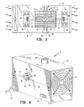
- Figure 3 is a top plan view of Figure 2.
- Figure 4 is a perspective partially broken view of another embodiment of the invention showing the exterior thereof.
- one embodiment of the invention is shown generally at numeral 10 and includes an extruded tubular aluminum outwardly finned heat sink 12 which is horizontally disposed atop a mounting platform 30 .
- a double ended arc-discharge lamp 14 Positioned centrally within and along the length of heat sink 12 is a double ended arc-discharge lamp 14 having its end terminals 16 operably connected within sockets 38 of terminal blocks 18 . These terminal blocks 18 are also connected to platform 30 as shown.
- the device 10 also includes a plurality of rigid cylindrical transparent rods 22 which are connected adjacent their inner end within mating holes or ports 24 formed through the wall of heat sink 12 .
- Each end of each transparent rod is ground parallel and polished to a suitable finish.
- the inner ends 40 of each of the transparent rods 22 are positioned in close proximity to arc lamp 14 .
- each of the transparent rods 22 are coated at 40 with a dielectric layer such as a hot mirror coating having a zero degree (0′) angle of incidence which is selected to reflect infrared radiation in the wave length range of about 750 to 1200 nanometers (nm.).
- the full-spectrum light emitting from the arc lamp 14 includes both ultraviolet and infrared radiation in the wave length range of less than 450 (nm.) and greater than 750 (nm.), respectively, as well as light in the visible range.
- a portion of the undesirable infrared radiation is initially reflected back and prevented from being transmitted through each transparent rod 22 by the dielectric coating 40 applied to each inner end of transparent rods 24 . This reflected back infrared radiation is dissipated into heat sink 14 and then radiated into the surrounding air.
- the fins of heat sink 12 assist in this heat dissipation.
- Transparent rod 22 is preferably formed of heat resistant glass such as "PYREX", an Owens Corning product.
- quartz glass will also serve the purpose of both transmitting the light passing through dielectric layer 40 , while also absorbing the ultraviolet wavelength components in the range of less than 450 (nm.).
- the visible light emitting from the outer end 28 of transparent rods 22 is absent both ultraviolet radiation and infrared radiation up to about 1200 (nm).
- an additional transparent disc 26 is also provided in this embodiment 10 which includes an additional hot mirror coating on the inner surface thereof which mates against the outer end 28 .
- This "hot mirror coating” is selected also having a zero degree (0′) angle of incidence to reflect infrared radiation above 1200 (nm.). Again this infrared component is reflected back inwardly through each transparent rod 22 into the interior of heat sink 12 for dissipation.
- an enclosure 20 formed having opaque side and top panels is also provided so as to eliminate glare from arc lamp 14 .
- a small axial flow fan 32 Disposed at one end of enclosure 20 is a small axial flow fan 32 which introduces air into the interior of enclosure 20 to carry heat out through discharge grill 34 .
- Transparent mirror discs 26 are connected against the interior surface of the walls of enclosure 20 and aligned with an aperture therethrough shown typically at 64 in Figure 3.
- a fiber optic bundle (not shown) may then be positioned against the exterior of enclosure 20 in alignment with each of the transparent rods 22 as desired.
- a thin initialized aluminum coating is also deposited on the longitudinal cylindrical surface only thereof.
- FIG. 42 another embodiment of the invention is shown at numeral 42 and includes substantially all of the components as previously described within the interior thereof.
- An opaque enclosure 44 includes an air discharge grill 46 at one end and a cooling fan (not shown) at the opposite end.
- Each of the transparent glass rods 50 in this embodiment 42 exit the enclosure 44 through a mating hole formed in the walls thereof and are connected within tubular couplings 48 which are, in turn connected to an outer wall surface of enclosure 44 .
- a set screw 54 retains this arrangement.
- the fiber optic bundles may each then be inserted into the remaining interior length 58 of one tubular coupling 48 and held in position and alignment directly against the outer end 52 of each transparent rod 50 by set screw 56 .
- the enclosure 44 also includes an on/off switch 60 which controllably applies electric power via electrical cable 62 to the arc discharge lamp 14 contained therein and as previously described.
Landscapes
- Physics & Mathematics (AREA)
- Spectroscopy & Molecular Physics (AREA)
- Engineering & Computer Science (AREA)
- General Engineering & Computer Science (AREA)
- General Physics & Mathematics (AREA)
- Optics & Photonics (AREA)
- Arrangement Of Elements, Cooling, Sealing, Or The Like Of Lighting Devices (AREA)
- Optical Couplings Of Light Guides (AREA)
- Light Sources And Details Of Projection-Printing Devices (AREA)
- Non-Portable Lighting Devices Or Systems Thereof (AREA)
- Surface Treatment Of Glass Fibres Or Filaments (AREA)
Applications Claiming Priority (2)
| Application Number | Priority Date | Filing Date | Title |
|---|---|---|---|
| US07/777,156 US5111367A (en) | 1991-10-16 | 1991-10-16 | Fiber optic lighting device |
| US777156 | 1996-12-26 |
Publications (2)
| Publication Number | Publication Date |
|---|---|
| EP0542427A2 true EP0542427A2 (fr) | 1993-05-19 |
| EP0542427A3 EP0542427A3 (en) | 1993-09-22 |
Family
ID=25109443
Family Applications (1)
| Application Number | Title | Priority Date | Filing Date |
|---|---|---|---|
| EP19920309367 Withdrawn EP0542427A3 (en) | 1991-10-16 | 1992-10-14 | Fiber optic lighting device |
Country Status (3)
| Country | Link |
|---|---|
| US (1) | US5111367A (fr) |
| EP (1) | EP0542427A3 (fr) |
| CA (1) | CA2079304C (fr) |
Families Citing this family (21)
| Publication number | Priority date | Publication date | Assignee | Title |
|---|---|---|---|---|
| JP3354162B2 (ja) * | 1991-04-26 | 2002-12-09 | 富士通株式会社 | 走査装置 |
| US5560700A (en) * | 1992-01-31 | 1996-10-01 | Massachusetts Institute Of Technology | Light coupler |
| US5371660A (en) * | 1992-01-31 | 1994-12-06 | Massachusetts Institute Of Technology | Illumination system and method |
| US5295052A (en) * | 1992-10-09 | 1994-03-15 | Luxtec Corporation | Light source assembly |
| GB9307906D0 (en) * | 1993-04-16 | 1993-06-02 | Eurotec Fibre Optics Ltd | Improvements relating to fibre optic bundle arrangements |
| US5568007A (en) * | 1993-07-28 | 1996-10-22 | Jasco Corporation | Lamp unit and optical analyzer using the same |
| US5420769A (en) * | 1993-11-12 | 1995-05-30 | General Electric Company | High temperature lamp assembly with improved thermal management properties |
| US5653519A (en) * | 1993-12-16 | 1997-08-05 | Glass Illuminations, Inc. | Fiber optics illuminator system |
| GB2298055B (en) * | 1995-02-14 | 1999-09-15 | Eurotec Fibre Optics Ltd | Improvements relating to light transmission means |
| US5779353A (en) * | 1996-04-16 | 1998-07-14 | Fiberstars, Inc. | Weather-protected lighting apparatus and method |
| JPH09327435A (ja) * | 1996-06-12 | 1997-12-22 | Fuji Photo Optical Co Ltd | 内視鏡用光源装置 |
| US6027237A (en) * | 1997-03-17 | 2000-02-22 | Remote Source Lighting International, Inc. | Air router for cooling light guide bundle |
| EP0911578A3 (fr) | 1997-06-02 | 1999-07-28 | Rohm And Haas Company | Dispositif d'éclairage pour fibre optique |
| US6068385A (en) * | 1998-03-18 | 2000-05-30 | Hsieh; Jordan | Durable lamp having air cooled moveable bulb |
| US6247830B1 (en) * | 1998-07-29 | 2001-06-19 | Russell Winnett | Heat shield for agricultural light bulb |
| US6201915B1 (en) | 1998-10-13 | 2001-03-13 | Physical Optics Corporation | High efficiency lighting system having a remote light source |
| US6450677B1 (en) | 2000-09-21 | 2002-09-17 | Robert M. Knauer | Fiberoptic lighting system |
| US6863421B2 (en) * | 2001-06-11 | 2005-03-08 | Infocus Corporation | Lamphouse |
| US7387403B2 (en) * | 2004-12-10 | 2008-06-17 | Paul R. Mighetto | Modular lighting apparatus |
| US20060126346A1 (en) * | 2004-12-10 | 2006-06-15 | Paul R. Mighetto | Apparatus for providing light |
| AT11351U1 (de) * | 2009-04-21 | 2010-09-15 | Swarovski & Co | Dekorativer verbundkörper |
Family Cites Families (15)
| Publication number | Priority date | Publication date | Assignee | Title |
|---|---|---|---|---|
| DE1153189B (de) * | 1961-06-30 | 1963-08-22 | Zeiss Ikon Ag | Anordnung zur Abtrennung der Waerme-strahlung aus dem Strahlengang einer Lichtquelle |
| DE1201278B (de) * | 1962-05-04 | 1965-09-23 | Quarzlampen Gmbh | Operationsleuchte |
| US3455622A (en) * | 1964-06-29 | 1969-07-15 | George D Cooper | Lighting device for transmitting visible radiant energies to inaccessible places |
| DE1497325A1 (de) * | 1966-07-30 | 1969-10-30 | Original Hanau Quarzlampen | Operationsleuchte mit Streuscheibe |
| US3586851A (en) * | 1969-02-24 | 1971-06-22 | Robert R Rudolph | Cool light |
| US3681592A (en) * | 1969-07-14 | 1972-08-01 | Ernie & Co Fa | Luminous energizer for fiber-optical cables |
| US4563589A (en) * | 1984-01-09 | 1986-01-07 | Scheffer Herbert D | Ultraviolet curing lamp device |
| JPS6217904A (ja) * | 1985-07-15 | 1987-01-26 | 双葉電子工業株式会社 | 光源 |
| US4740870A (en) * | 1987-03-05 | 1988-04-26 | Moore Eric L | Fiber optic system for boats |
| US4825341A (en) * | 1987-11-17 | 1989-04-25 | Fiberstars, Inc. | Cooled lighting apparatus and method |
| DE3824371A1 (de) * | 1988-03-05 | 1989-09-14 | Aqua Signal Ag | Beleuchtungseinrichtung, insbesondere fuer schiffe |
| DE3814539A1 (de) * | 1988-04-29 | 1989-11-09 | Heraeus Gmbh W C | Beleuchtungsanordnung mit halogengluehlampe |
| US4958263A (en) * | 1988-11-02 | 1990-09-18 | General Electric Company | Centralized lighting system employing a high brightness light source |
| US5016152A (en) * | 1989-09-21 | 1991-05-14 | Fiberstars, Inc. | Focused light source and method |
| US5001616A (en) * | 1990-03-16 | 1991-03-19 | American Sterilizer Company | Optical system for lighting fixture |
-
1991
- 1991-10-16 US US07/777,156 patent/US5111367A/en not_active Expired - Fee Related
-
1992
- 1992-09-28 CA CA002079304A patent/CA2079304C/fr not_active Expired - Fee Related
- 1992-10-14 EP EP19920309367 patent/EP0542427A3/en not_active Withdrawn
Also Published As
| Publication number | Publication date |
|---|---|
| CA2079304C (fr) | 1996-02-06 |
| CA2079304A1 (fr) | 1993-04-17 |
| EP0542427A3 (en) | 1993-09-22 |
| US5111367A (en) | 1992-05-05 |
Similar Documents
| Publication | Publication Date | Title |
|---|---|---|
| US5111367A (en) | Fiber optic lighting device | |
| US5099399A (en) | High efficiency fiber optics illuminator with thermally controlled light guide bushing | |
| KR0120825B1 (ko) | 중앙 광원으로부터 단열된 분산 광 네트워크 | |
| US5076660A (en) | Light source receptacle for fiberoptic illumination | |
| US20090316385A1 (en) | Led lighting fixture | |
| US5860723A (en) | Light engine with ellipsoidal reflector | |
| KR20010071393A (ko) | 광원 시스템 내에 광화이버 요소를 장착하기 위한 스냅-인커넥터 | |
| US5761356A (en) | Apparatus and method for coupling high intensity light into low temperature optical fiber | |
| US5513291A (en) | Light source modifications for plastic light fibre compatibility | |
| US6007226A (en) | Fiber optic light | |
| US7062129B2 (en) | Fiber optic illuminating apparatus and method | |
| EP0658722A1 (fr) | Boîtier cubique pour système lumineux | |
| CN1123060C (zh) | 光输出器件及其制作方法及其阵列 | |
| US6070985A (en) | Multiport illuminator for light guides | |
| WO1997043675A1 (fr) | Conception mecanique d'un dispositif d'eclairage multiport pour macro-fibres | |
| KR100283770B1 (ko) | 열관리기구를 구비한 조명장치 | |
| WO1997015853A1 (fr) | Systeme modulaire d'eclairage par fibres optiques | |
| HUT73895A (en) | Light generator with reflective enclosure for a lighting or illuminating system using light guides | |
| JP2002517014A (ja) | 光ガイドの放物線状及び球形マルチポート照明装置 | |
| CA2425474A1 (fr) | Lampadaires a fibres optiques | |
| KR100516360B1 (ko) | 발광 소자 어레이(array)장치 및 그 제조 방법 | |
| GB2250354A (en) | Light reflector | |
| US20080055923A1 (en) | High efficiency light projector | |
| JP2001014940A (ja) | 光ファイバー照明の光源装置 | |
| WO1999042870A1 (fr) | Systeme d'eclairage a orifices multiples pour guides de lumiere |
Legal Events
| Date | Code | Title | Description |
|---|---|---|---|
| PUAI | Public reference made under article 153(3) epc to a published international application that has entered the european phase |
Free format text: ORIGINAL CODE: 0009012 |
|
| AK | Designated contracting states |
Kind code of ref document: A2 Designated state(s): BE DE FR GB IE IT |
|
| PUAL | Search report despatched |
Free format text: ORIGINAL CODE: 0009013 |
|
| AK | Designated contracting states |
Kind code of ref document: A3 Designated state(s): BE DE FR GB IE IT |
|
| 18D | Application deemed to be withdrawn |
Effective date: 19940323 |