EP0542606A1 - Hydraulisch verriegelter Steuerstrahlregler - Google Patents
Hydraulisch verriegelter Steuerstrahlregler Download PDFInfo
- Publication number
- EP0542606A1 EP0542606A1 EP92403007A EP92403007A EP0542606A1 EP 0542606 A1 EP0542606 A1 EP 0542606A1 EP 92403007 A EP92403007 A EP 92403007A EP 92403007 A EP92403007 A EP 92403007A EP 0542606 A1 EP0542606 A1 EP 0542606A1
- Authority
- EP
- European Patent Office
- Prior art keywords
- chambers
- chamber
- blocking
- movable bar
- supply
- Prior art date
- Legal status (The legal status is an assumption and is not a legal conclusion. Google has not performed a legal analysis and makes no representation as to the accuracy of the status listed.)
- Ceased
Links
Images


Classifications
-
- F—MECHANICAL ENGINEERING; LIGHTING; HEATING; WEAPONS; BLASTING
- F42—AMMUNITION; BLASTING
- F42B—EXPLOSIVE CHARGES, e.g. FOR BLASTING, FIREWORKS, AMMUNITION
- F42B10/00—Means for influencing, e.g. improving, the aerodynamic properties of projectiles or missiles; Arrangements on projectiles or missiles for stabilising, steering, range-reducing, range-increasing or fall-retarding
- F42B10/60—Steering arrangements
- F42B10/66—Steering by varying intensity or direction of thrust
- F42B10/663—Steering by varying intensity or direction of thrust using a plurality of transversally acting auxiliary nozzles, which are opened or closed by valves
-
- B—PERFORMING OPERATIONS; TRANSPORTING
- B64—AIRCRAFT; AVIATION; COSMONAUTICS
- B64G—COSMONAUTICS; VEHICLES OR EQUIPMENT THEREFOR
- B64G1/00—Cosmonautic vehicles
- B64G1/22—Parts of, or equipment specially adapted for fitting in or to, cosmonautic vehicles
- B64G1/40—Arrangements or adaptations of propulsion systems
- B64G1/402—Propellant tanks; Feeding propellants
-
- F—MECHANICAL ENGINEERING; LIGHTING; HEATING; WEAPONS; BLASTING
- F02—COMBUSTION ENGINES; HOT-GAS OR COMBUSTION-PRODUCT ENGINE PLANTS
- F02K—JET-PROPULSION PLANTS
- F02K9/00—Rocket-engine plants, i.e. plants carrying both fuel and oxidant therefor; Control thereof
- F02K9/80—Rocket-engine plants, i.e. plants carrying both fuel and oxidant therefor; Control thereof characterised by thrust or thrust vector control
- F02K9/805—Rocket-engine plants, i.e. plants carrying both fuel and oxidant therefor; Control thereof characterised by thrust or thrust vector control servo-mechanisms or control devices therefor
-
- B—PERFORMING OPERATIONS; TRANSPORTING
- B64—AIRCRAFT; AVIATION; COSMONAUTICS
- B64G—COSMONAUTICS; VEHICLES OR EQUIPMENT THEREFOR
- B64G1/00—Cosmonautic vehicles
- B64G1/22—Parts of, or equipment specially adapted for fitting in or to, cosmonautic vehicles
- B64G1/24—Guiding or controlling apparatus, e.g. for attitude control
- B64G1/26—Guiding or controlling apparatus, e.g. for attitude control using jets
-
- B—PERFORMING OPERATIONS; TRANSPORTING
- B64—AIRCRAFT; AVIATION; COSMONAUTICS
- B64G—COSMONAUTICS; VEHICLES OR EQUIPMENT THEREFOR
- B64G1/00—Cosmonautic vehicles
- B64G1/22—Parts of, or equipment specially adapted for fitting in or to, cosmonautic vehicles
- B64G1/40—Arrangements or adaptations of propulsion systems
- B64G1/401—Liquid propellant rocket engines
Definitions
- the present invention relates to a pneumatically locked jet switch. It applies in particular to the control of trajectories of vehicles in space, these vehicles being driven by thrusts caused by gases which they release. More generally, it applies to the control of pitch, yaw and roll of air vehicles in applications where the aerodynamic control surfaces prove to be ineffective as is the case for example at low speed or at very high altitude, when the vacuum is almost reached.
- a solution generally consists, starting from a single gas source, for example a combustion of a block of propellant, in switching jets of gas coming from this source towards outlet nozzles whose directions are such that they allow the control of the movements of the machine, at the level of roll, pitch or yaw; the gas jets leaving a nozzle imposing on the machine a reverse thrust to their direction due to the principle of conservation of the momentum.
- An important organ for controlling these movements is therefore the jet switch; this switches for example the gas jets from one nozzle to the other according to the defined trajectory.
- Many types of jet switches have already been made. For example, the switch described in the US patent.
- the object of the invention is to overcome the aforementioned drawbacks by providing in particular a movable bar whose movement is controlled by the gas itself and very simple valves.
- the subject of the invention is a pneumatic locking jet switch supplying at least two nozzles, comprising outlet chambers connected to the nozzles, supply chambers connected to gas inlet conduits, a movable bar whose position allows alternately to close either one or the other of the partitions separating the outlet chambers from the feed chambers, from the blocking chambers closed by valves, characterized in that the movable bar contains conduits borrowing connecting the outlet chambers to the blocking chambers, the blocking chambers being separated from the supply chambers each by a movable partition secured to the movable bar and whose surface in contact with the blocking chambers is greater than the surface of the ends of the bar mobile, a valve being closed beforehand, this valve being associated with the blocking chamber connected to the outlet chamber closed relative to s a feed chamber, the opening of the outlet chamber on its feed chamber by displacement of the movable bar being triggered by the opening of the valve associated with the blocking chamber connected to the outlet chamber open on its chamber power supply.
- the main advantages of the invention are that it allows a reduction in the consumption of gas and the electrical consumption of the electromagnets, that it allows the reduction in size, weight and cost of the latter, finally that it achieves very short switching times.
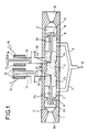
- Figure 1 shows a sectional view of a possible embodiment of a jet switch according to the invention. It mainly consists of a body whose cross-section is hatched, in which moves a movable bar 2 with symmetry of revolution for example.
- This jet switch makes it possible to supply two nozzles 34 and 35 via outlet chambers 3 and 4 each situated at one of its ends, these nozzles can be oriented in any way. It is itself supplied by a gas jet symbolized by the arrow G, the gas passing through the inlet conduits 5 and 6.
- the supply gas can be, for example, a hot gas originating from the combustion of a propellant block or gas from a pressurized volume. These conduits open inside the switch in chambers 7 and 8, called supply chambers.
- the feed chamber 7 is separated from the outlet chamber by an open partition 9 from the body 1 of the switch, the feed chamber 8 is separated from the outlet chamber 4 by an open partition 10.
- the outlet chambers 3, 4 can be isolated from the supply chambers 7, 8 by their closure by the ends 11, 12 of the movable bar 2.
- Electromagnets whose coils 13, 14 are supplied by lines 15, 16 respectively control the position of pistons 17, 18.
- seal chambers 21, 22 of the switch called blocking chamber, with respect to exhaust ducts 19, 20, in contact for example with atmospheric pressure.
- the blocking chamber 21 is hermetically separated from the supply chamber 7 by a wider part 23 of the movable bar 2, acting as a partition integral with the bar 2.
- the blocking chamber 22 is separated from the chamber supply 8 by a wider part 24 of the movable bar 2.
- the parts 23 and 24 of the movable bar will subsequently be called movable partitions.
- Gas can pass from the outlet chamber 3 to the blocking chamber 21 via a conduit 25, called a borrow conduit, inside the movable bar 2.
- gas can pass from the outlet chamber 4 to the blocking chamber 22 by means of a borrow duct 26 inside the movable bar 2.
- the switch according to the invention is open on the side of the outlet chamber 3 and closed on the side of the outlet chamber 4.
- the supply chamber 8, the supply conduits 5 and 6, the chamber supply 7, the outlet chamber 3, the borrowing conduit 25 and the blocking chamber 21 are at the pressure of the supply gas.
- the outlet chamber 4, the borrowing conduit 26, the blocking chamber 22 are at ambient pressure, for example atmospheric pressure. From the state illustrated in FIG. 1, stable, a communication consists in opening the partition 10 by the end 12 of the movable bar 2 and in closing the partition 9 by the end 11 of the movable bar 2.
- FIG. 2 illustrates the operation of the switch according to the invention.
- the switch is in the closed position on the side of the outlet chamber 3.
- the valves produced by the pistons in FIG. 1 are symbolized by the signs 27 and 28. In fact, it is possible to envisage any type of valve, and other means than pistons and electromagnets could be used.
- the arrows associated with the letter P symbolize the force exerted by the pressure of the gas on the transverse walls of the movable bar 2.
- the outlet chamber 4, the supply chamber 8, the blocking chamber 22 and the supply chamber 7 are at the pressure of the supply gas. This pressure is denoted P, relative value with respect to the ambient pressure, atmospheric pressure for example.
- the pressures of the outlet chambers 3, 4 and blocking 21, 22 are always the same thanks to the borrowing conduits 25, 26.
- a first condition for proper operation is that in the closed position, the movable bar 2 remains stable. According to the invention, this is possible on the one hand, thanks to the borrowing conduits 25 and 26 and on the other hand, thanks to the value of the surfaces of the ends 11, 12 and parts 23, 24 forming the partition of the movable bar 2 To check it, it suffices to take stock of the forces pushing the movable bar towards a point A located at the nozzle 34 and the balance of forces pushing the mobile towards a point B, located on the opposite side of the nozzle 35 in the case where the valve 28 is closed for example, the state of the valve 27 being indifferent. The pressure being the same in the two supply chambers 7 and 8, the forces due to these pressures therefore cancel each other out.
- the relative ambient pressure P amb is here 0, and the surfaces of the movable partition 23 in contact with the blocking chamber 21 as well as the surface of the face of the end 11 opposite point A are the same as those defined above. .
- the valve 27 having been closed beforehand, the switching of gas jets, therefore in fact the switching of the movable bar 2 from the closing of the partition 9 to the closing of the partition 10, is carried out by opening the valve 28.
- the blocking chamber 22 becomes at atmospheric pressure for example.
- the valve 27 having been previously closed, thanks to the borrowing conduit 25, the blocking chamber 21 becomes subjected to the same pressure as the outlet chamber 3, that is to say to the pressure of the gas. food. In fact, it is the pressure of the gas occupying this blocking chamber 21 which keeps the movable bar 2 in a locked position.
- the previously established force balances become inverted, they are illustrated in FIG. 3b, and consequently, the movable bar 2 remains in a stable position, closing the outlet chamber 4. To bring it back to the previous position, it will first be necessary close the valve 28, then open the valve 27, the phenomenon described above will occur again.
- the exhaust conduits 29, 30 at the outlet from the blocking chambers must have a diameter greater than the borrow conduits 25, 26 so that, in the event of opening, the blocking chambers can be found at atmospheric pressure, otherwise they would remain subject to gas pressure, the exhaust pipes would then act as leakage pipes.
- the jet switch according to the invention makes it possible to minimize the dimensions of the electromagnet.
- the piston 17 closes the exhaust duct of the locking chamber 21 to maintain the latter under the gas pressure.
- FIGS. 4a, 4b, 4c and 4d illustrate the different states of an electromagnet as a function of the different states of a switch according to the invention. These figures show the electromagnet consisting of the coil 13 seen in section and of the piston 17 of FIG. 1.
- the lower part of the piston 17 is no longer enlarged, and corresponds to a frequent case where the exhaust ducts 19 , 20 have a relatively small cross section.
- the structure 41 makes it possible to connect the electromagnet and the exhaust ducts to the body 1 of the switch according to the invention.
- FIG. 4a shows the state of an electromagnet before switching.
- the piston rod 17 which controls this switching closes the exhaust duct 19.
- the electromagnet has to overcome the pressure forces exerted on the diameter of the exhaust duct 19. The latter being generally small, these forces are minimal .
- the electromagnet working at zero air gap, a reduced current I, brought by the wires of the line 15, is sufficient to generate sufficient force for the enlarged upper part 42 of the piston 17 to remain in contact. of the electromagnet.
- This air gap is defined by the space e between the coil 13 of the electromagnet and the enlarged upper part 42 of the piston 17, as shown in FIG. 4b.
- FIG. 4c represents a stable state where the switching is carried out, there is no longer any pressure greater than ambient or atmospheric pressure in the duct 29.
- the piston is shown in the high position, with maximum air gap, but in fact its position is indifferent for the operation of the jet switch according to the invention. Indeed, in this state the partition 9 of the switch is closed and the outlet chamber 3 being at ambient pressure, it is the same for the chamber 21 therefore for the conduit 29 thanks to the borrowing conduit 25 and that whatever that is to say the position of the piston 17. Nevertheless, in order to prepare the next switching operation, it is necessary to close off the exhaust duct 19, so that during this switching operation, the blocking chamber 21 remains at the pressure of the gases. The re-blocking phase of the piston 17 is presented in FIG. 4d.
- the electromagnet is supplied by a current I.
- this works at maximum air gap but n 'has more to overcome the pressure due to gases, so consumption is still in this very moderate phase.
- this blocking phase of the piston 17 can begin as soon as the pressure drops in the blocking chamber 21, therefore in the duct 29, and the time to achieve this blocking can last until the start of the next switching.
- the direction of movement of the piston 17 is indicated by the arrow F2.
- the blocking chamber is ready to withstand the gas pressure to which it will be subjected on the next switching which will be triggered by the other electromagnet 14 which will open the blocking chamber 22 towards the exhaust duct 20.
- a jet switch according to the invention if it uses electromagnets to control its openings, therefore makes it possible to make them work at zero air gap when they have a pressure force to overcome and at maximum air gap when this pressure force has faded away. This therefore makes it possible to minimize the size and the mass of the electromagnets as well as their electrical consumption and therefore thereby, the size and the mass of the electrical generation members. Furthermore, it appears that to trigger a switching, it is sufficient, as in the case of FIG. 4b, to cancel a supply current, which makes it possible to simplify control procedures and decrease switching times.
Landscapes
- Engineering & Computer Science (AREA)
- Chemical & Material Sciences (AREA)
- Combustion & Propulsion (AREA)
- General Engineering & Computer Science (AREA)
- Remote Sensing (AREA)
- Aviation & Aerospace Engineering (AREA)
- Mechanical Engineering (AREA)
- Physics & Mathematics (AREA)
- Fluid Mechanics (AREA)
- Driving Mechanisms And Operating Circuits Of Arc-Extinguishing High-Tension Switches (AREA)
Applications Claiming Priority (2)
| Application Number | Priority Date | Filing Date | Title |
|---|---|---|---|
| FR9114097A FR2683861B1 (fr) | 1991-11-15 | 1991-11-15 | Commutateur de jets a verrouillage pneumatique. |
| FR9114097 | 1991-11-15 |
Publications (1)
| Publication Number | Publication Date |
|---|---|
| EP0542606A1 true EP0542606A1 (de) | 1993-05-19 |
Family
ID=9418979
Family Applications (1)
| Application Number | Title | Priority Date | Filing Date |
|---|---|---|---|
| EP92403007A Ceased EP0542606A1 (de) | 1991-11-15 | 1992-11-06 | Hydraulisch verriegelter Steuerstrahlregler |
Country Status (2)
| Country | Link |
|---|---|
| EP (1) | EP0542606A1 (de) |
| FR (1) | FR2683861B1 (de) |
Families Citing this family (2)
| Publication number | Priority date | Publication date | Assignee | Title |
|---|---|---|---|---|
| RU2232285C2 (ru) * | 2002-04-24 | 2004-07-10 | ФГУП "Челябинский автоматно-механический завод" | Газореактивная система |
| RU2311579C1 (ru) * | 2006-09-14 | 2007-11-27 | Открытое акционерное общество "Бердский электромеханический завод" | Газораспределительное устройство |
Citations (6)
| Publication number | Priority date | Publication date | Assignee | Title |
|---|---|---|---|---|
| US3721402A (en) * | 1971-06-25 | 1973-03-20 | Us Army | Missile roll control mechanism |
| US4078495A (en) * | 1974-08-15 | 1978-03-14 | The United States Of America As Represented By The Secretary Of The Navy | Control after burnout for reaction steered missiles |
| EP0060726A2 (de) * | 1981-03-17 | 1982-09-22 | Normalair-Garrett (Holdings) Limited | Strahltrieb-Schubsysteme |
| EP0112755A2 (de) * | 1982-12-17 | 1984-07-04 | Thomson-Brandt Armements | Mit seitlich ausströmenden Gasstrahlen arbeitende Steuervorrichtung |
| EP0149947A2 (de) * | 1984-01-06 | 1985-07-31 | Thomson-Brandt Armements | Gasdüsenantrieb für lenkbare Rakete |
| US4826104A (en) * | 1986-10-09 | 1989-05-02 | British Aerospace Public Limited Company | Thruster system |
-
1991
- 1991-11-15 FR FR9114097A patent/FR2683861B1/fr not_active Expired - Lifetime
-
1992
- 1992-11-06 EP EP92403007A patent/EP0542606A1/de not_active Ceased
Patent Citations (6)
| Publication number | Priority date | Publication date | Assignee | Title |
|---|---|---|---|---|
| US3721402A (en) * | 1971-06-25 | 1973-03-20 | Us Army | Missile roll control mechanism |
| US4078495A (en) * | 1974-08-15 | 1978-03-14 | The United States Of America As Represented By The Secretary Of The Navy | Control after burnout for reaction steered missiles |
| EP0060726A2 (de) * | 1981-03-17 | 1982-09-22 | Normalair-Garrett (Holdings) Limited | Strahltrieb-Schubsysteme |
| EP0112755A2 (de) * | 1982-12-17 | 1984-07-04 | Thomson-Brandt Armements | Mit seitlich ausströmenden Gasstrahlen arbeitende Steuervorrichtung |
| EP0149947A2 (de) * | 1984-01-06 | 1985-07-31 | Thomson-Brandt Armements | Gasdüsenantrieb für lenkbare Rakete |
| US4826104A (en) * | 1986-10-09 | 1989-05-02 | British Aerospace Public Limited Company | Thruster system |
Also Published As
| Publication number | Publication date |
|---|---|
| FR2683861B1 (fr) | 1995-03-31 |
| FR2683861A1 (fr) | 1993-05-21 |
Similar Documents
| Publication | Publication Date | Title |
|---|---|---|
| EP1040274B1 (de) | Verdrängungspumpe | |
| CA1325578C (fr) | Groupe motopropulseur a accumulateur elastique d'elasticite variable et vehicule comportant un tel groupe | |
| EP0646525B1 (de) | Zweidimensionaler Über- und Hyperschall-Lufteinlauf mit drei bewegbaren Rampen für die Verbrennungsluft eines Flugzeugmotors | |
| FR2776015A1 (fr) | Organe d'echappement a echangeur de chaleur | |
| CA2923212C (fr) | Dispositif d'alimentation en fluide hydraulique d'un verin et mecanisme de commande de pas des pales d'une helice de turbomoteur comportant le verin | |
| CH626167A5 (de) | ||
| EP0462874B1 (de) | Stossdämpfer eines Flugzeuges | |
| FR2734025A1 (fr) | Moteur fusee a propergol liquide, a impulsions | |
| EP0064433B1 (de) | Lenkbarer Flugkörper | |
| FR3021347A1 (fr) | Moteur a air comprime a chambre active incluse et a distribution active a l'admission | |
| FR2641829A1 (fr) | Servomecanisme commande par un fluide | |
| WO1997018389A1 (fr) | Inverseur de poussee de turboreacteur a obstacles aval tendant a l'equilibrage | |
| EP1964740B1 (de) | Neuartige funktionelle Architektur eines Vakuumkreislaufs in einem Kraftfahrzeug zur Erhaltung der Integrität der pneumatischen Stellglieder oder Aufnehmer | |
| EP0542606A1 (de) | Hydraulisch verriegelter Steuerstrahlregler | |
| EP0354103A1 (de) | Zweidimensionaler und asymmetrischer Überschall-Lufteinlauf für die Verbrennungsluft eines Flugzeugmotors | |
| EP2881571B1 (de) | Vorrichtung zur Kontrolle eines einströmenden Gasflusses und/oder rückgeführten Abgasflusses in einem Zylinder eines Verbrennungsmotors, und entsprechendes Ansaugmodul | |
| FR2960259A1 (fr) | Compresseur thermodynamique | |
| EP0362053B1 (de) | Konstruktion eines Kombinationsantriebs für zwei Funktionstypen | |
| EP0066795A1 (de) | Schnell schliessendes Ventil für komprimierbares Fluidum | |
| FR2873175A1 (fr) | Circuit hydraulique comprenant un selecteur multifonction | |
| FR2745606A1 (fr) | Statoreacteur a geometrie evolutive pour aeronef | |
| FR2635076A1 (fr) | Entree d'air supersonique et hypersonique bidimensionnelle et symetrique pour l'air de combustion d'un moteur d'aeronef | |
| FR2786810A1 (fr) | Dispositif de commande des soupapes d'echange de gaz d'un moteur a combustion interne | |
| FR2806146A1 (fr) | Dispositif de commande electromagnetique de soupapes, a ressorts pneumatiques | |
| FR3053411A1 (fr) | Systeme de propulsion a inertie comportant un freinage par un fluide de la trajectoire retour de la masse |
Legal Events
| Date | Code | Title | Description |
|---|---|---|---|
| PUAI | Public reference made under article 153(3) epc to a published international application that has entered the european phase |
Free format text: ORIGINAL CODE: 0009012 |
|
| AK | Designated contracting states |
Kind code of ref document: A1 Designated state(s): DE FR GB SE |
|
| 17P | Request for examination filed |
Effective date: 19930821 |
|
| 17Q | First examination report despatched |
Effective date: 19950112 |
|
| STAA | Information on the status of an ep patent application or granted ep patent |
Free format text: STATUS: THE APPLICATION HAS BEEN REFUSED |
|
| 18R | Application refused |
Effective date: 19950702 |