EP0542611B1 - Sicherheitsvorrichtung für eine Schubumkehrvorrichtung eines Flugtriebwerks - Google Patents
Sicherheitsvorrichtung für eine Schubumkehrvorrichtung eines Flugtriebwerks Download PDFInfo
- Publication number
- EP0542611B1 EP0542611B1 EP19920403016 EP92403016A EP0542611B1 EP 0542611 B1 EP0542611 B1 EP 0542611B1 EP 19920403016 EP19920403016 EP 19920403016 EP 92403016 A EP92403016 A EP 92403016A EP 0542611 B1 EP0542611 B1 EP 0542611B1
- Authority
- EP
- European Patent Office
- Prior art keywords
- door
- safety installation
- unlocking
- prevention mechanism
- installation according
- Prior art date
- Legal status (The legal status is an assumption and is not a legal conclusion. Google has not performed a legal analysis and makes no representation as to the accuracy of the status listed.)
- Expired - Lifetime
Links
- 238000009434 installation Methods 0.000 claims description 21
- 230000002265 prevention Effects 0.000 claims 11
- 230000000694 effects Effects 0.000 description 3
- 239000000470 constituent Substances 0.000 description 2
- 230000000903 blocking effect Effects 0.000 description 1
- 238000006757 chemical reactions by type Methods 0.000 description 1
- 230000005284 excitation Effects 0.000 description 1
Images

Classifications
-
- F—MECHANICAL ENGINEERING; LIGHTING; HEATING; WEAPONS; BLASTING
- F02—COMBUSTION ENGINES; HOT-GAS OR COMBUSTION-PRODUCT ENGINE PLANTS
- F02K—JET-PROPULSION PLANTS
- F02K1/00—Plants characterised by the form or arrangement of the jet pipe or nozzle; Jet pipes or nozzles peculiar thereto
- F02K1/54—Nozzles having means for reversing jet thrust
- F02K1/76—Control or regulation of thrust reversers
- F02K1/766—Control or regulation of thrust reversers with blocking systems or locking devices; Arrangement of locking devices for thrust reversers
-
- E—FIXED CONSTRUCTIONS
- E05—LOCKS; KEYS; WINDOW OR DOOR FITTINGS; SAFES
- E05B—LOCKS; ACCESSORIES THEREFOR; HANDCUFFS
- E05B47/00—Operating or controlling locks or other fastening devices by electric or magnetic means
- E05B47/0001—Operating or controlling locks or other fastening devices by electric or magnetic means with electric actuators; Constructional features thereof
- E05B47/0002—Operating or controlling locks or other fastening devices by electric or magnetic means with electric actuators; Constructional features thereof with electromagnets
-
- E—FIXED CONSTRUCTIONS
- E05—LOCKS; KEYS; WINDOW OR DOOR FITTINGS; SAFES
- E05B—LOCKS; ACCESSORIES THEREFOR; HANDCUFFS
- E05B47/00—Operating or controlling locks or other fastening devices by electric or magnetic means
- E05B47/06—Controlling mechanically-operated bolts by electro-magnetically-operated detents
- E05B47/0607—Controlling mechanically-operated bolts by electro-magnetically-operated detents the detent moving pivotally or rotatively
-
- E—FIXED CONSTRUCTIONS
- E05—LOCKS; KEYS; WINDOW OR DOOR FITTINGS; SAFES
- E05C—BOLTS OR FASTENING DEVICES FOR WINGS, SPECIALLY FOR DOORS OR WINDOWS
- E05C3/00—Fastening devices with bolts moving pivotally or rotatively
- E05C3/12—Fastening devices with bolts moving pivotally or rotatively with latching action
- E05C3/16—Fastening devices with bolts moving pivotally or rotatively with latching action with operating handle or equivalent member moving otherwise than rigidly with the latch
- E05C3/22—Fastening devices with bolts moving pivotally or rotatively with latching action with operating handle or equivalent member moving otherwise than rigidly with the latch the bolt being spring controlled
- E05C3/24—Fastening devices with bolts moving pivotally or rotatively with latching action with operating handle or equivalent member moving otherwise than rigidly with the latch the bolt being spring controlled in the form of a bifurcated member
-
- E—FIXED CONSTRUCTIONS
- E05—LOCKS; KEYS; WINDOW OR DOOR FITTINGS; SAFES
- E05B—LOCKS; ACCESSORIES THEREFOR; HANDCUFFS
- E05B47/00—Operating or controlling locks or other fastening devices by electric or magnetic means
- E05B47/0001—Operating or controlling locks or other fastening devices by electric or magnetic means with electric actuators; Constructional features thereof
- E05B47/0002—Operating or controlling locks or other fastening devices by electric or magnetic means with electric actuators; Constructional features thereof with electromagnets
- E05B2047/0007—Operating or controlling locks or other fastening devices by electric or magnetic means with electric actuators; Constructional features thereof with electromagnets with two or more electromagnets
-
- E—FIXED CONSTRUCTIONS
- E05—LOCKS; KEYS; WINDOW OR DOOR FITTINGS; SAFES
- E05B—LOCKS; ACCESSORIES THEREFOR; HANDCUFFS
- E05B47/00—Operating or controlling locks or other fastening devices by electric or magnetic means
- E05B47/0001—Operating or controlling locks or other fastening devices by electric or magnetic means with electric actuators; Constructional features thereof
- E05B47/0002—Operating or controlling locks or other fastening devices by electric or magnetic means with electric actuators; Constructional features thereof with electromagnets
- E05B47/0003—Operating or controlling locks or other fastening devices by electric or magnetic means with electric actuators; Constructional features thereof with electromagnets having a movable core
- E05B47/0004—Operating or controlling locks or other fastening devices by electric or magnetic means with electric actuators; Constructional features thereof with electromagnets having a movable core said core being linearly movable
Definitions
- the present invention relates to a safety installation intended to equip thrust reversers with doors for an aircraft engine of the reaction type.
- the thrust reversers with which certain types of aircraft engine are fitted are intended to slow down the aircraft during landing by causing the jet engine to deflect forward. Their implementation is always voluntarily ordered during the landing maneuver and must be prohibited during the flight phases, since any untimely deployment of the reverser doors would pose considerable risks to the aircraft.
- the door thrust reversers are fitted with safety devices ensuring effective locking of the doors in the retracted position when the aircraft is in flight.
- there is at least one door lock ensuring the locking of the door in the closed position and at least one door actuating cylinder, cylinder which is subjected to a means adapted to lock it. in the position it occupies when the door is closed.
- An actuating circuit for example an electro-hydraulic circuit, ensures, to allow the doors to be opened, the operation, with a view to unlocking them and according to a predetermined sequence, first of the door latch and then of the means of door actuator locking.
- a mechanism can also be provided for preventing the door lock from being unlocked.
- GB-A-759 891 describes a system in which unlocking prohibition means constituted by hooks are operated under the effect of the actuation of the door opening cylinders.
- the present invention proposes to reinforce security by providing that the mechanism for preventing the unlocking of the door latch is associated with a control circuit independent of the actuation circuit ensuring the operation of the door latch and of the cylinder locking means, which control circuit acts positively on said unlocking prohibition mechanism (26; 260) both to move and maintain the latter in the door lock unlocking prohibition position as in a position allowing said lock to be unlocked.
- the door lock mounted on the door comprises a tilting part which cooperates with a fixed part of the structure of the engine nacelle, tilting part capable of moving between a locked position and a position open, the bringing and holding of the tilting part in its locked position being produced by a locking lever pivoting about a fixed axis and actuated by the piston of a jack, said tilting piece, said locking lever and said cylinder piston moving in the same plane and constituting a kinematic chain.
- the unlocking prohibition mechanism consists of at least one movable part capable of moving between, on the one hand, a prohibition position in which it abuts with one constituents of said kinematic chain which it prevents from moving, thereby blocking the entire kinematic chain as long as the control circuit of the prohibition mechanism with which it is associated is not actuated and, on the other hand, a position withdrawal obtained under the action of said control circuit and in which it leaves the constituents of said kinematic chain free to move.
- said movable part such as a finger
- said movable finger is electrically controlled, independently of the actuation circuit of the kinematic chain.
- the movable finger can be located in the same plane as the transverse chain or transverse to it.
- two electromagnets are used, situated on either side of the kinematic plane, and actuating two prohibition fingers situated in the extension one of the other.
- the prohibition mechanism will advantageously cooperate with the unlocking lever and more especially with an arm of the lever situated opposite the tilting part with respect to the pivot axis of the lever.
- each inverter door comprises several safety installations mounted in series on the same electro-hydraulic actuation circuit.
- each inverter door can have several safety installations mounted in series.
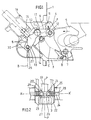
- the safety installation mounted on the structure 1 has a casing 3 open on its front face at 4 for the passage of a tilting part 5 in the form of a hook belonging to a lock intended to cooperate with part of the door 2, for locking it.
- the part 5 is pivotally mounted around a fixed axis 7 and biased in its open position, shown in broken lines at 5 ′, by a spring 8 wound around the axis 7.
- a locking lever 9, pivotally mounted about a fixed axis 10, has an arm 11 terminated by a roller 12 and intended to cooperate with the part 5 of the lock, and an arm 13, opposite the arm 11 relative to the axis 10, which cooperates with the end of the piston 15 of a hydraulic cylinder 16 housed in the casing 3.
- the jack 16 is mounted on an electro-hydraulic circuit (not shown), possibly in series with other safety installations with which the door can be fitted, and the output of the piston 15 causes the lever 9 to tilt in the direction of arrow F, which unlocks part 5 of the lock which can then open to allow the door to open under the effect of a control jack, not shown, acting directly on the door.
- This door actuator as already indicated, itself comprises a locking means (not shown) mounted on the same actuation circuit as the actuator 16.
- part 5 of the lock, the lever 9 and the piston 15 of cylinder 16 constitute a kinematic chain, the members of which are located in the same plane P (FIG. 2).
- the casing 3 (see FIG. 2) has two internal protuberances 20-21 aligned along a common axis X-X ′ transverse to the plane P of the kinematic chain.
- the walls of the housing are pierced with housings 22 extended, on the inside, by orifices 23 of smaller diameter.
- the rod 24 of an electromagnet core 25 fixed to the outside on each side of the casing.
- the ends 26 of the rods 24 protrude inside the casing 3 to be housed in an opening 27 made in the end of the arm 13 of the lever 9.
- the rods 24 are biased in the position of FIG. 2 by springs 28 mounted around said rods 24 in the housings 22 and acting between the body 25 of the electromagnet and a stop flange 29.
- the electromagnets 25 are electrically controlled independently of all of the components of the kinematic chain and their excitation results in the withdrawal of the end 26 of the rods 24 from the opening 27 of the lever which is thus released, allowing good operation of the piston 15.
- the arm 13 of the lever 9 is extended by an ear 30 which, when the lever 9 is tilted in the release position of the latch 5, serves as a stop for the rods 24 when the electromagnets 25 are de-energized, in order to allow lever 9 easily return to its position in solid lines under the effect of its spring 17.
- the movable part 260 is constituted by a lever articulated around an axis 261 and located in the plane of the kinematic chain formed by the locking lever 91, the part tilting 5 and the piston 15.
- One of the arms 262 of the moving part 260 is biased in the solid line position by a spring member 263, to come into contact with the arm 130 of the lever 91.
- an electromagnet 264 controls the tilting of the part 260 towards its position in broken lines by acting on the second arm 265 of the part 260 opposite the arm 262 relative to the axis 261.
Landscapes
- Engineering & Computer Science (AREA)
- Mechanical Engineering (AREA)
- Chemical & Material Sciences (AREA)
- Combustion & Propulsion (AREA)
- General Engineering & Computer Science (AREA)
- Physics & Mathematics (AREA)
- Electromagnetism (AREA)
- Lock And Its Accessories (AREA)
- Devices For Conveying Motion By Means Of Endless Flexible Members (AREA)
Claims (9)
- Sicherheitsanlage für eine an einem Flugzeug-Strahltriebwerk montierte Schubumkehrvorrichtung mit Klappen, die für jede Klappe (2) mindestens einen Klappenriegel, der die Verriegelung der Klappe in geschlossener Stellung gewährleistet, mindestens einen Klappenbetätigungszylinder, der der Einwirkung eines Mittels ausgesetzt ist, das ihn in der Stellung, die er bei geschlossener Klappe einnimmt, verriegeln kann, und mindestens einen Betätigungskreis aufweist, der, um die Öffnung der Klappe (2) zu gestatten, die Manövrierung zunächst des Klappenriegels und dann des Mittels zur Verriegelung des Klappenbetätigungszylinders zum Zweck ihrer Entriegelung und in einer vorbestimmten Sequenz gewährleistet, wobei diese Anlage außerdem einen Mechanismus (26, 260) zur Sperrung der Entriegelung des Klappenriegels aufweist, dadurch gekennzeichnet, daß dieser Mechanismus (26, 260) einem Steuerkreis (25, 264) zugeordnet ist, der von diesem Betätigungskreis unabhängig ist und auf diesen Mechanismus (26, 260) zur Sperrung der Entriegelung positiv einwirkt, um diesen sowohl in die Stellung der Sperrung der Entriegelung des Klappenriegels (2) als auch in eine die Entriegelung dieses Riegels gestattende Stellung zu bewegen und in dieser zu halten.
- Sicherheitsanlage nach Anspruch 1, in welcher der Klappenriegel ein schwenkbares Teil (5) aufweist, das sich zwischen einer verriegelten Stellung und einer offenen Stellung bewegen kann, wobei die Einführung des schwenkbaren Teils (5) in seine verriegelte Stellung und sein Halt in dieser durch einen Verriegelungshebel (9; 91) erreicht werden, der sich um eine feststehende Achse (7; 261) dreht und durch den Kolben (15) eines Arbeitszylinders (16) betätigt ist, wobei dieses schwenkbare Teil (5), dieser Verriegelungshebel (9; 91) und dieser Arbeitszylinderkolben (15) sich in ein und der selben Ebene (P) bewegen und eine kinematische Kette bilden, dadurch gekennzeichnet, daß der Mechanismus zur Sperrung der Entriegelung aus mindestens einem beweglichen Teil (24; 260) besteht, das sich bewegen kann zwischen einerseits einer Sperrstellung, in der es an einem der Elemente (5, 9 oder 91, 15) dieser kinematischen Kette in Anschlag kommt, dessen Bewegung es verhindert, indem es so die gesamte kinematische Kette blockiert, solange der Steuerkreis (25; 264) dieses Sperrmechanismus, dem es zugeordnet ist, nicht betätigt ist, und andererseits einer weggerückten Stellung, die durch Einwirkung dieses Steuerkreises (25; 264) erreicht wird und in der es die Bewegung der Elemente (5, 9 oder 91, 15) der kinematischen Kette frei zuläßt.
- Sicherheitsanlage nach Anspruch 2, dadurch gekennzeichnet, daß dieses bewegliche Teil (24; 260) elektrisch unabhängig vom Betätigungskreis (25; 264) dieser kinematischen Kette (5, 9 oder 91, 15) gesteuert wird.
- Sicherheitsanlage nach Anspruch 2 oder 3, dadurch gekennzeichnet, daß der Mechanismus (24; 260) zur Sperrung der Entriegelung mit diesem Verriegelungshebel (9; 91) zusammenwirkt.
- Sicherheitsanlage nach Anspruch 3 oder 4, dadurch gekennzeichnet, daß der Mechanismus zur Sperrung der Entriegelung aus zwei Elektromagneten (25) , die zu beiden Seiten der Ebene (P) angeordnet sind, in der die kinematische Kette (5, 9, 15) liegt, und aus zwei Sperrdaumen (26) als bewegliche Teile besteht, die in der gegenseitigen Verlängerung liegen.
- Sicherheitsanlage nach einem der Ansprüche 3 bis 5, dadurch gekennzeichnet, daß der oder die beweglichen Teile (24) des Mechanismus zur Sperrung der Entriegelung mit einer Aufnahme (27) zusammenwirken, die einen Arm (13) dieses Verriegelungshebels (9) durchquert, die bezüglich der Drehachse (10) dieses Hebels entgegengesetzt zu diesem verschwenkbaren Teil (5) angeordnet ist.
- Sicherheitsanlage nach Anspruch 6,
dadurch gekennzeichnet, daß dieser Arm (13) des Verriegelungshebels (9) über die durchquerende Aufnahme (27) hinaus durch einen Fortsatz (30) verlängert ist, der mit dem oder den beweglichen Teilen (24) des Mechanismus zur Sperrung der Entriegelung zusammenwirkt, wenn dieses bzw. diese in der weggerückten Stellung sind und der Verriegelungshebel (9) in die Stellung geschwenkt ist, die die Öffnung des Klappenriegels zuläßt. - Sicherheitsanlage nach einem der Ansprüche 2 bis 4, dadurch gekennzeichnet, daß dieses bewegliche Teil (260) aus einem schwenkbaren Hebel besteht, der in derselben Ebene (P) wie diese kinematische Kette (5, 91, 15) gelegen ist.
- Einheit bestehend aus einer Vielzahl von Sicherheitsanlagen, die in einem gemeinsamen Betätigungskreis in Reihe geschaltet sind und dazu bestimmt sind, eine an einem Flugzeug-Strahltriebwerk montierte Schubumkehrklappe auszurüsten, dadurch gekennzeichnet, daß nur die erste Sicherheitsanlage der Reihe gemäß einem der Ansprüche 1 bis 8 ausgebildet ist.
Applications Claiming Priority (2)
| Application Number | Priority Date | Filing Date | Title |
|---|---|---|---|
| FR9114011A FR2683860B1 (fr) | 1991-11-14 | 1991-11-14 | Installation de securite pour inverseur de poussee a portes equipant un avion et ensemble incorporant une telle installation. |
| FR9114011 | 1991-11-14 |
Publications (2)
| Publication Number | Publication Date |
|---|---|
| EP0542611A1 EP0542611A1 (de) | 1993-05-19 |
| EP0542611B1 true EP0542611B1 (de) | 1995-10-25 |
Family
ID=9418903
Family Applications (1)
| Application Number | Title | Priority Date | Filing Date |
|---|---|---|---|
| EP19920403016 Expired - Lifetime EP0542611B1 (de) | 1991-11-14 | 1992-11-09 | Sicherheitsvorrichtung für eine Schubumkehrvorrichtung eines Flugtriebwerks |
Country Status (3)
| Country | Link |
|---|---|
| EP (1) | EP0542611B1 (de) |
| DE (1) | DE69205665T2 (de) |
| FR (1) | FR2683860B1 (de) |
Families Citing this family (15)
| Publication number | Priority date | Publication date | Assignee | Title |
|---|---|---|---|---|
| GB9215496D0 (en) * | 1992-07-21 | 1992-09-02 | Lucas Ind Plc | Lock for an engine thrust reverser |
| GB9320447D0 (en) * | 1993-10-05 | 1993-12-22 | Lucas Ind Plc | Lock for an engine thrust reverser |
| FR2711187B1 (fr) * | 1993-10-15 | 1996-02-02 | Aerospatiale | Turboréacteur à double flux entouré d'une ceinture de reprise d'efforts liée à au moins une porte pivotante des inverseurs de poussée. |
| FR2712635B1 (fr) * | 1993-11-19 | 1996-08-09 | Hurel Dubois Avions | Inverseur de poussée à portes pour moteur d'avion équipé de systèmes de sécurité interdisant l'ouverture intempestive des portes. |
| GB9418895D0 (en) * | 1994-09-20 | 1994-11-09 | Lucas Ind Plc | Lock mechanism |
| AU1336197A (en) * | 1995-07-31 | 1997-02-26 | Vladimir Jurievich Petelin | Electromechanical lock |
| DE69514224T2 (de) * | 1995-09-13 | 2000-08-10 | Societe De Construction Des Avions Hurel-Dubois (S.A.), Meudon-La-Foret | Elektrohydraulische Schubumkehrvorrichtung mit zwei Klappen |
| GB2305460B (en) * | 1995-09-25 | 1999-12-15 | Dowty Boulton Paul Ltd | Lock for engine thrust reverser |
| GB9907614D0 (en) * | 1999-04-06 | 1999-05-26 | Lucas Ind Plc | Lock for a thrust reverser |
| GB0002392D0 (en) * | 2000-02-02 | 2000-03-22 | Dowty Boulton Paul Ltd | Locks and locking systems |
| FR2846378B1 (fr) | 2002-10-25 | 2006-06-30 | Hispano Suiza Sa | Inverseur de poussee electromecanique pour turboreacteur a synchronisation des dispositifs de verrouillage |
| FR2860554B1 (fr) * | 2003-10-06 | 2005-12-23 | Hurel Hispano | Verrou pour inverseur de poussee, muni d'un dispositif de blocage |
| US9109536B2 (en) | 2013-03-14 | 2015-08-18 | Woodward Hrt, Inc. | Engine thrust reverser lock |
| ES2662056T3 (es) * | 2015-05-22 | 2018-04-05 | Kale Kilit Ve Kalip Sanayi A.S. | Cerradura de gancho de alta seguridad |
| CN121498938B (zh) * | 2026-01-14 | 2026-04-10 | 成都航利装备科技有限公司 | 一种航空发动机反推力装置闭合锁扣检测方法及装置 |
Family Cites Families (5)
| Publication number | Priority date | Publication date | Assignee | Title |
|---|---|---|---|---|
| US2780057A (en) * | 1954-02-23 | 1957-02-05 | Boeing Co | Locks for jet thrust reversers |
| GB921917A (en) * | 1961-05-31 | 1963-03-27 | Gen Electric | A control mechanism for the thrust reverser blocker doors of a jet propulsion engine |
| US3576337A (en) * | 1969-03-21 | 1971-04-27 | Rohr Corp | Locking system |
| US3600023A (en) * | 1970-02-09 | 1971-08-17 | Rohr Corp | Locking system |
| GB2154291B (en) * | 1984-02-14 | 1987-08-12 | Rolls Royce | Anti rotation device |
-
1991
- 1991-11-14 FR FR9114011A patent/FR2683860B1/fr not_active Expired - Fee Related
-
1992
- 1992-11-09 DE DE1992605665 patent/DE69205665T2/de not_active Expired - Fee Related
- 1992-11-09 EP EP19920403016 patent/EP0542611B1/de not_active Expired - Lifetime
Also Published As
| Publication number | Publication date |
|---|---|
| EP0542611A1 (de) | 1993-05-19 |
| FR2683860B1 (fr) | 1995-04-28 |
| DE69205665T2 (de) | 1996-07-04 |
| DE69205665D1 (de) | 1995-11-30 |
| FR2683860A1 (fr) | 1993-05-21 |
Similar Documents
| Publication | Publication Date | Title |
|---|---|---|
| EP0542611B1 (de) | Sicherheitsvorrichtung für eine Schubumkehrvorrichtung eines Flugtriebwerks | |
| EP1298309B1 (de) | Blockierungssystem für eine Strahlumkehrvorrichtung mit verschiebbarem Bläsergehäuse | |
| EP1342663B1 (de) | Sperreinrichtung und zugehöriges Betriebsverfahren, insbesondere für ein Flugzeugfahrwerk | |
| CA2234437C (fr) | Inverseur de poussee protege au deverrouillage pour turbomoteur d'aeronef | |
| WO2019238476A1 (fr) | Poignée de porte affleurante et son procédé de fonctionnement | |
| WO1998014699A1 (fr) | Procede et dispositifs de fermeture des portes d'inverseur de poussee | |
| FR2765916A1 (fr) | Inverseur de poussee a resistance amelioree aux impacts | |
| FR2823258A1 (fr) | Systeme de verrouillage de secours pour porte d'inverseur de poussee | |
| FR2775717A1 (fr) | Dispositif d'ouverture/fermeture d'un ouvrant, notamment pour vehicule automobile | |
| FR2654767A1 (fr) | Mecanisme de commande d'ouverture d'une portiere de vehicule automobile et portiere le comportant. | |
| EP3584157B1 (de) | Verfahren zum bewegen von frachtraumtüren des fahrwerks eines luftfahrzeugs | |
| EP0541422B1 (de) | Sicherheitsverriegelungsvorrichtung mit umkippbarem Zurückhaltehaken | |
| EP3877252B1 (de) | Notöffnungsvorrichtung für eine flugzeugtür mit drehfreigabe | |
| FR2686568A1 (fr) | Porte d'aeronef pressurise, permettant d'evacuer la pression residuelle interne avant son ouverture et de limiter la mise en pression tant qu'elle n'est pas completement fermee. | |
| FR2546219A1 (fr) | Appareil electrique de verrouillage et deverrouillage a distance adaptable sur les barres antipanique dites a bascule | |
| EP0151063A2 (de) | Vorrichtung zum automatischen oder manuellen Öffnen von Türen von Behälter von Sicherheitsausrüstung | |
| FR2704907A1 (fr) | Système auto-bloquant de commande des portes d'inverseur de poussée d'un turboréacteur. | |
| EP0297971B1 (de) | Vorrichtung zum Öffnen und Schliessen von Türen mit der Möglichkeit einer Zwischenöffnung, insbesondere für Drahtseilbahnkabinen | |
| EP4594177A1 (de) | Mechanismus zum verriegeln einer tür in kreisförmiger translation | |
| FR3150784A1 (fr) | Dispositif d’armement de toboggan de porte d’aéronef semi-plug à dégagement latéral. | |
| FR2681633A1 (fr) | Dispositif de verrouillage de securite a crochet basculant. | |
| FR2766225A1 (fr) | Dispositif d'ouverture/fermeture des ouvrants d'un vehicule automobile | |
| FR2768503A1 (fr) | Dispositif de commande automatique d'au moins un element mobile tel qu'une derive ventrale de missile | |
| FR2739648A1 (fr) | Ensemble constitue par une serrure de porte de vehicule automobile et ses organes de commande | |
| FR2671371A1 (fr) | Dispositif anti-panique de deverrouillage instantane d'un mecanisme de serrure. |
Legal Events
| Date | Code | Title | Description |
|---|---|---|---|
| PUAI | Public reference made under article 153(3) epc to a published international application that has entered the european phase |
Free format text: ORIGINAL CODE: 0009012 |
|
| AK | Designated contracting states |
Kind code of ref document: A1 Designated state(s): DE FR GB |
|
| 17P | Request for examination filed |
Effective date: 19931025 |
|
| 17Q | First examination report despatched |
Effective date: 19941202 |
|
| GRAA | (expected) grant |
Free format text: ORIGINAL CODE: 0009210 |
|
| AK | Designated contracting states |
Kind code of ref document: B1 Designated state(s): DE FR GB |
|
| REF | Corresponds to: |
Ref document number: 69205665 Country of ref document: DE Date of ref document: 19951130 |
|
| GBT | Gb: translation of ep patent filed (gb section 77(6)(a)/1977) |
Effective date: 19960122 |
|
| PLBE | No opposition filed within time limit |
Free format text: ORIGINAL CODE: 0009261 |
|
| STAA | Information on the status of an ep patent application or granted ep patent |
Free format text: STATUS: NO OPPOSITION FILED WITHIN TIME LIMIT |
|
| 26N | No opposition filed | ||
| PGFP | Annual fee paid to national office [announced via postgrant information from national office to epo] |
Ref country code: GB Payment date: 20011016 Year of fee payment: 10 |
|
| PGFP | Annual fee paid to national office [announced via postgrant information from national office to epo] |
Ref country code: FR Payment date: 20011127 Year of fee payment: 10 |
|
| REG | Reference to a national code |
Ref country code: FR Ref legal event code: CD |
|
| PGFP | Annual fee paid to national office [announced via postgrant information from national office to epo] |
Ref country code: DE Payment date: 20011228 Year of fee payment: 10 |
|
| REG | Reference to a national code |
Ref country code: GB Ref legal event code: IF02 |
|
| PG25 | Lapsed in a contracting state [announced via postgrant information from national office to epo] |
Ref country code: GB Free format text: LAPSE BECAUSE OF NON-PAYMENT OF DUE FEES Effective date: 20021109 |
|
| PG25 | Lapsed in a contracting state [announced via postgrant information from national office to epo] |
Ref country code: DE Free format text: LAPSE BECAUSE OF NON-PAYMENT OF DUE FEES Effective date: 20030603 |
|
| GBPC | Gb: european patent ceased through non-payment of renewal fee | ||
| PG25 | Lapsed in a contracting state [announced via postgrant information from national office to epo] |
Ref country code: FR Free format text: LAPSE BECAUSE OF NON-PAYMENT OF DUE FEES Effective date: 20030731 |
|
| REG | Reference to a national code |
Ref country code: FR Ref legal event code: ST |