EP0542696B1 - Interrupteur à pression ayant un microrupteur de sécurité actionné manuellement - Google Patents
Interrupteur à pression ayant un microrupteur de sécurité actionné manuellement Download PDFInfo
- Publication number
- EP0542696B1 EP0542696B1 EP92830550A EP92830550A EP0542696B1 EP 0542696 B1 EP0542696 B1 EP 0542696B1 EP 92830550 A EP92830550 A EP 92830550A EP 92830550 A EP92830550 A EP 92830550A EP 0542696 B1 EP0542696 B1 EP 0542696B1
- Authority
- EP
- European Patent Office
- Prior art keywords
- pressure switch
- microswitch
- safety
- operating
- membrane
- Prior art date
- Legal status (The legal status is an assumption and is not a legal conclusion. Google has not performed a legal analysis and makes no representation as to the accuracy of the status listed.)
- Expired - Lifetime
Links
Images

Classifications
-
- H—ELECTRICITY
- H01—ELECTRIC ELEMENTS
- H01H—ELECTRIC SWITCHES; RELAYS; SELECTORS; EMERGENCY PROTECTIVE DEVICES
- H01H35/00—Switches operated by change of a physical condition
- H01H35/24—Switches operated by change of fluid pressure, by fluid pressure waves, or by change of fluid flow
- H01H35/34—Switches operated by change of fluid pressure, by fluid pressure waves, or by change of fluid flow actuated by diaphragm
Definitions
- the present invention relates to a pressure switch having a manually operated safety microswitch.
- Such a construction in addition to requiring very complex machining steps, also includes several zones in which there is at least partially modified the resiliency of the membrane with a consequent random variation of the trip operation characteristics of the assembly.
- a further drawback is that the tappet assembly included in these prior pressure switches is usually welded at the central region of the membrane, which contributes to a further changing of the mechanic and resiliency properties of the membrane.
- a pressure switch comprising a bottom body defining in its inside a chamber communicating with a fluid to be controlled, and being associated with a top cap, supporting an operating switching contacts, said chamber being closed by a membrane, and including a sealing O-ring and being coupled to a steel membrane, with a related driving tappet assembly, said assembly being directly formed on the latter membrane and driving a washer counterbiassed by a first counterbiassing spring, and affecting said switching contacts.
- the aim of the present invention is to overcome the above mentioned drawbacks, by providing a pressure switch, including a manually operated safety microswitch, which provides a perfect tightness with respect to the fluid to be controlled, without requiring any welding operations, so as to greatly improve the resilient responsivity of the membrane.
- a main object of the present invention is to provide such a pressure switch, the tapped assembly whereof is made as an integrating portion of the membrane, so as not to modify the physical and operation properties of said membrane.
- Yet another object of the present invention is to provide such a pressure switch in which the operation threshold of the membrane can be easily modified in order to quickly and easily fit it to the specific use requirements.
- Yet another object of the present invention is to provide such a pressure switch which is very reliable and safe in operation and can be easily made from easily commercially available elements and materials and which, moreover, is very competitive from a mere economic standpoint.
- a pressure switch including a manually operated safety microswitch, characterized in that said pressure switch comprises a bottom body defining in its inside a chamber communicating with a fluid to be controlled, and being associated with a top cap, supporting an operating microswitch, said chamber being closed by a membrane, preferably made of a silicone material, and including a sealing O-ring and being coupled to a steel membrane, with a related driving tappet assembly, said assembly being directly formed on the latter membrane and driving a washer counterbiassed by a first counterbiassing spring, and affecting a push-button of the operating microswitch, a safety manually operated microswitch being moreover provided cooperating with a pin element extending from said washer.
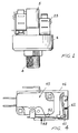
- the pressure switch including a manually operated safety microswitch, according to the present invention, which has been generally indicated at the reference number 1, comprises a bottom body, or base cap 2 which, in its inside, defines a chamber 3 which, through a duct 4, is communicated with a fluid the pressure of which must be detected or sensed.
- a top cap 5 associated with said bottom body by means of a metal circumferential edging 6.
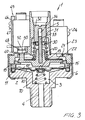
- the chamber 3 is closed by a membrane 10 which is formed as a single body with a sealing peripheral inner O-ring, adapted to provide a perfect tightness, said membrane being preferably made of a silicone or other suitable material.
- Said silicone material membrane 10 is connected to a stainless steel membrane 12 which is super-imposed on said membrane 10 and is provided, at the central region thereof, with an integral tappet assembly 13.
- said membranes 10 and 12 are held in a set position by means of a safety ring element 11 which is circumferentially engaged with the membrane 12 and holds in its preset position the sealing O-ring 11 so as to provide both the metallic clamping effect and an accurate tightness provided by said O-ring.
- the tappet assembly 13 affects the central portion of a washer element 20, which is slidably guided on the top cap 5 and supports an aluminium disc 21, having a variable thickness, so as to adjust the operating threshold on the push-button 22 of an operating microswitch 23 which is connected to said cap 5 by means of screws 24.
- a first biassing spring 30 which is coaxially arranged with respect to the washer and houses a top sliding bush 31 which contacts an adjusting screw 32 in turn rotatably supported by the cap 5.
- a guide pin 33 is moreover provided, for guiding the washer, which can slide in a hollow 34 formed inside the adjusting screw 32.
- a pin element 40 which cooperates with a manually operated safety microswitch, generally indicated at the reference number 45, which is supported by the cap 5 by means of a ryton small plate 46, restrained by screws 47.
- the microswitch 45 is provided with an operating lever 48, thereon the pin 40 can operate at different points, which can be set by means of a plurality of engaging slots 50 provided through the cap, in order to allow the lever arm to be easily changed.
- a further thrust spring can moreover be provided.
- the lever 48 operates the push-button 52 of the safety microswitch 45 and, at one end portion thereof, interacts with a resilient locking tongue 60, having a lug 61, and which is so arranged as to easily change its latching conditions (see figure 4).
- a latching spring 62 operating between the locking tongue 60 and the wall of the small plate 46, in order to prevent the resiliency characteristics of the tongue from varying in the time.
- a manually resettable microswitch which does not comprise any small plate
- a second biassing spring 70 operating in the chamber 3 on the membrane, so as to allow the possibility of presetting a plurality of operating threshold values, with a very small working pressure.
- a possible failure of the microswitch 23 is compensated for by the operation of the safety microswitch, which will be brought to its locking position, with a consequent need of performing a manual resetting operation, by operating the locking lever 60.
- the calibrating or rated values can be easily modified by operating, for example, the adjusting screw 32, by introducing several aluminium discs of different thicknesses, in order to reduce the operating travel or by introducing a further biassing spring, operating on the underside of the membrane 10.
- a pressure switch has been provided adapted to provide very accurate threshold values, since its membrane is not welded but is peripherally held through the interposition of a resilient material membrane, made of a resilient material such as silicone or the like, which is moreover provided with a tightness or sealing O-ring.
- the subject pressure switch can also be provided with two operating microswitches.
- the used materials provided that they are compatible to the intended use, as well as the contingent size and shapes, can be any, according to requirements.
Landscapes
- Physics & Mathematics (AREA)
- Fluid Mechanics (AREA)
- Switches Operated By Changes In Physical Conditions (AREA)
- Push-Button Switches (AREA)
- Switches With Compound Operations (AREA)
Claims (17)
- Un interrupteur à pression (1) incluant un microrupteur (45) de sûreté actionné à la main, comprenant un corps inférieur (2) définissant dans son intérieur une chambre (3) communiquant avec un fluide qui doit être contrôlé, et associé à un couvercle (5) supérieur supportant un microrupteur de démarrage (23), ladite chambre (3) étant fermée par une membrane (10), faite préférablement d'un matérieau en silicone, et incluant un joint d'étanchéité annulaire (11) et reliée à une membrane en acier (12), avec un dispositif de commande à poussoir (13), ledit dispositif (13) étant directement formé sur cette dernière membrane (12) et agissant sur une rondelle (20), contrechargée par un premier ressort tendeur (30), et influençant un bouton-poussoir (22) du microrupteur de démarrage (23), un microrupteur de sûreté (45) actionné à la main étant de plus mis en oeuvre lequel coopère avec une cheville (40) saillant de ladite rondelle (20).
- Un interrupteur à pression selon la revendication 1, caractérisé en ce que l'interrupteur à pression (1) comprend un élément annulaire de sûreté (15) intercalé entre le corps inférieur (2) et le couvercle (5) et agissant sur la périphérie de ladite membrane (12).
- Un interrupteur à pression (1) selon les revendications 1 et 2, caractérisé en ce que ledit interrupteur à pression (1) comprend une vis d'ajustage (32) agissant sur le premier ressort de réaction (30) et supportée par ledit couvercle (5) de sorte à être en état de tourner.
- Un interrupteur à pression selon l'une ou plusieurs des revendications précédentes, caractérisé en ce que ledit interrupteur à pression (1) comprend un coulisseau (31) intercalé entre un bout du premier ressort de réaction (30) et la vis d'ajustage (32).
- Un interrupteur à pression selon l'une ou plusieurs des revendications précédentes, caractérisé en ce que ledit microrupteur de sûreté (45) est du type réarmé démarré à la main.
- Un interrupteur à pression selon l'une ou plusieurs des revendications précédentes, caractérisé en ce qu'il comprend en outre sur ledit microrupteur de sûreté (45) un levier (48) coopérant avec le bouton-poussoir (52) du microrupteur de sûreté (45) et susceptible d'être actionné par la cheville (40).
- Un interrupteur à pression selon l'une ou plusieurs des revendications précédentes, caractérisé en ce que ledit levier (48) agit sur un ressort de calibration.
- Un interrupteur à pression selon l'une ou plusieurs des revendications précédentes, caractérisé en ce que ledit interrupteur à pression (1) comprend en outre sur ledit couvercle (5) une multiplicité d'ouvertures (50) de dispositions variées, pour permettre à ladite cheville (40) d'y passer à travers, idoines à mettre en oeuvre un point de fonctionnement variable de ladite cheville (40) sur le levier de commande (48) du microrupteur de sûreté (45).
- Un interrupteur à pression selon l'une ou plusieurs des revendications précédentes, caractérisé en ce que ledit interrupteur à pression (1) comprend en outre, sur ladite rondelle (20), une vis d'ajustage coopérant avec ledit microrupteur de démarrage (23).
- Un interrupteur à pression selon l'une ou plusieurs des revendications précédentes, caractérisé en ce que ledit interrupteur à pression (1) comprend en outre, sur ladite rondelle (20), une vis d'ajustage et de calibration coopérant avec ledit microrupteur de sûreté (45).
- Un interrupteur à pression selon l'une ou plusieurs des revendications précédentes, caractérisé en ce que ledit interrupteur à pression (1) comprend en outre des éléments en disque en aluminium d'épaisseurs variées, situés sur ladite rondelle (20), afin de varier la course dudit microrupteur de démarrage (23).
- Un interrupteur à pression selon l'une ou plusieurs des revendications précédentes, caractérisé en ce que ledit interrupteur à pression (1) comprend en outre un second ressort de réaction (70) situé sous ladite membrane (10).
- Un interrupteur à pression selon l'une ou plusieurs des revendications précédentes, caractérisé en ce qu'il comprend une languette de verrouillage (60) pour réarmer à la main ledit microrupteur de sûreté (45).
- Un interrupteur à pression selon l'une ou plusieurs des revendications précédentes, caractérisé en ce que ledit interrupteur à pression (1) comprend en outre un ressort de verrouillage (62) agissant sur ladite languette de verrouillage (60) dudit microrupteur de sûreté (45).
- Un interrupteur à pression selon l'une ou plusieurs des revendications précédentes, caractérisé en ce que ledit interrupteur à pression (1) comprend en outre une partie en saillie (61) dont la forme peut être adaptée de sorte à varier les conditions de verrouillage entre ladite languette de verrouillage (60) et ledit levier dudit microrupteur de sûreté (45).
- Un interrupteur à pression selon l'une ou plusieurs des revendications précédentes, caractérisé en ce que ledit interrupteur à pression (1) est supporté par une plaque en ryton (46) reliée audit couvercle (5) moyennant des vis.
- Un interrupteur à pression selon l'une ou plusieurs des revendications précédentes, caractérisé en ce que ledit interrupteur à pression (1) comprend deux microrupteurs de démarrage (23, 45).
Applications Claiming Priority (2)
| Application Number | Priority Date | Filing Date | Title |
|---|---|---|---|
| ITMI913050A IT1258227B (it) | 1991-11-15 | 1991-11-15 | Pressostato con microinterruttore di sicurezza a riarmo manuale |
| ITMI913050 | 1991-11-15 |
Publications (3)
| Publication Number | Publication Date |
|---|---|
| EP0542696A2 EP0542696A2 (fr) | 1993-05-19 |
| EP0542696A3 EP0542696A3 (en) | 1993-07-28 |
| EP0542696B1 true EP0542696B1 (fr) | 1996-07-03 |
Family
ID=11361113
Family Applications (1)
| Application Number | Title | Priority Date | Filing Date |
|---|---|---|---|
| EP92830550A Expired - Lifetime EP0542696B1 (fr) | 1991-11-15 | 1992-10-01 | Interrupteur à pression ayant un microrupteur de sécurité actionné manuellement |
Country Status (5)
| Country | Link |
|---|---|
| EP (1) | EP0542696B1 (fr) |
| AT (1) | ATE140102T1 (fr) |
| DE (1) | DE69211956T2 (fr) |
| ES (1) | ES2091448T3 (fr) |
| IT (1) | IT1258227B (fr) |
Families Citing this family (1)
| Publication number | Priority date | Publication date | Assignee | Title |
|---|---|---|---|---|
| CN108962671A (zh) * | 2018-07-26 | 2018-12-07 | 陕西奉航橡胶密封件有限责任公司 | 一种商用车差速锁压力开关 |
Family Cites Families (6)
| Publication number | Priority date | Publication date | Assignee | Title |
|---|---|---|---|---|
| FR1543230A (fr) * | 1900-01-01 | Perfectionnements aux dispositifs de réglage thermique à sécurité incorporée | ||
| GB1217480A (en) * | 1968-06-18 | 1970-12-31 | Patinvest | Electric pressure-controlled snap switch |
| CH536547A (de) * | 1971-01-12 | 1973-04-30 | Danfoss As | Elektrischer Schnappschalter |
| US3898405A (en) * | 1974-01-11 | 1975-08-05 | Ernesto Juan Weber | Diaphragm pressure switch with balance plate and adjustable springs |
| GB2058456A (en) * | 1979-09-11 | 1981-04-08 | Lucas Industries Ltd | Monitoring gas pressure during charging of electric storage batteries |
| DE8103768U1 (de) * | 1981-02-12 | 1981-09-24 | Eaton S.A.M., Monaco | "Druckbetätigte elektrische Schaltvorrichtung" |
-
1991
- 1991-11-15 IT ITMI913050A patent/IT1258227B/it active IP Right Grant
-
1992
- 1992-10-01 EP EP92830550A patent/EP0542696B1/fr not_active Expired - Lifetime
- 1992-10-01 AT AT92830550T patent/ATE140102T1/de not_active IP Right Cessation
- 1992-10-01 DE DE69211956T patent/DE69211956T2/de not_active Expired - Fee Related
- 1992-10-01 ES ES92830550T patent/ES2091448T3/es not_active Expired - Lifetime
Also Published As
| Publication number | Publication date |
|---|---|
| ES2091448T3 (es) | 1996-11-01 |
| EP0542696A2 (fr) | 1993-05-19 |
| ITMI913050A0 (it) | 1991-11-15 |
| IT1258227B (it) | 1996-02-21 |
| DE69211956T2 (de) | 1997-02-27 |
| DE69211956D1 (de) | 1996-08-08 |
| ITMI913050A1 (it) | 1993-05-15 |
| EP0542696A3 (en) | 1993-07-28 |
| ATE140102T1 (de) | 1996-07-15 |
Similar Documents
| Publication | Publication Date | Title |
|---|---|---|
| US3516279A (en) | Method for adjusting a pressure operated switch utilizing the nonlinear properties of a biasing means | |
| EP0542695B1 (fr) | Interrupteur à pression ayant un microrupteur de sécurité actionné manuellement | |
| US2934618A (en) | Fluid pressure responsive switch | |
| EP0542696B1 (fr) | Interrupteur à pression ayant un microrupteur de sécurité actionné manuellement | |
| CA2056462C (fr) | Monocontact differentiel reglable sur place pour applications a basse pression de fluide | |
| US3932830A (en) | Push-to-turn thermal cycling switch | |
| US4626636A (en) | Pressure operated switch assembly with external pressure control | |
| US6346681B1 (en) | Pressure switch | |
| US2720564A (en) | Fluid pressure responsive switch | |
| US3566060A (en) | Pressure responsive switch with improved diaphragm operating means | |
| US3602863A (en) | Adjustable thermostat | |
| CA2016409C (fr) | Manostats | |
| US4464551A (en) | Electric circuit controlling device and method of operating same | |
| US3943479A (en) | Energy regulator | |
| US3182149A (en) | Pressure-operated control having means for adjusting the actuating pressures of a plurality of control switches | |
| US4160225A (en) | Temperature responsive control device with improved hydraulic diaphragm | |
| US3819888A (en) | Limit switch mechanism | |
| US2722580A (en) | Pressure switch | |
| US3742166A (en) | Pressure switch | |
| US5416970A (en) | Method of assembling a modular electric/gas oven thermostat | |
| US3348009A (en) | Calibration means for temperature responsive device | |
| US5315281A (en) | Thermostatically controlled switch | |
| US4403206A (en) | Balanced switch for thermostats or the like | |
| US3758732A (en) | E spring adjustment means fluid pressure actuated snap-action switch with differential and rang | |
| US3194916A (en) | Fluid operated switch actuator |
Legal Events
| Date | Code | Title | Description |
|---|---|---|---|
| PUAI | Public reference made under article 153(3) epc to a published international application that has entered the european phase |
Free format text: ORIGINAL CODE: 0009012 |
|
| AK | Designated contracting states |
Kind code of ref document: A2 Designated state(s): AT CH DE ES FR GB LI NL SE |
|
| PUAL | Search report despatched |
Free format text: ORIGINAL CODE: 0009013 |
|
| RHK1 | Main classification (correction) |
Ipc: H01H 35/34 |
|
| AK | Designated contracting states |
Kind code of ref document: A3 Designated state(s): AT CH DE ES FR GB LI NL SE |
|
| 17P | Request for examination filed |
Effective date: 19931123 |
|
| 17Q | First examination report despatched |
Effective date: 19951106 |
|
| GRAH | Despatch of communication of intention to grant a patent |
Free format text: ORIGINAL CODE: EPIDOS IGRA |
|
| GRAH | Despatch of communication of intention to grant a patent |
Free format text: ORIGINAL CODE: EPIDOS IGRA |
|
| GRAA | (expected) grant |
Free format text: ORIGINAL CODE: 0009210 |
|
| AK | Designated contracting states |
Kind code of ref document: B1 Designated state(s): AT CH DE ES FR GB LI NL SE |
|
| PG25 | Lapsed in a contracting state [announced via postgrant information from national office to epo] |
Ref country code: NL Free format text: LAPSE BECAUSE OF FAILURE TO SUBMIT A TRANSLATION OF THE DESCRIPTION OR TO PAY THE FEE WITHIN THE PRESCRIBED TIME-LIMIT Effective date: 19960703 Ref country code: AT Effective date: 19960703 |
|
| REF | Corresponds to: |
Ref document number: 140102 Country of ref document: AT Date of ref document: 19960715 Kind code of ref document: T |
|
| REF | Corresponds to: |
Ref document number: 69211956 Country of ref document: DE Date of ref document: 19960808 |
|
| PG25 | Lapsed in a contracting state [announced via postgrant information from national office to epo] |
Ref country code: SE Effective date: 19961003 |
|
| ET | Fr: translation filed | ||
| REG | Reference to a national code |
Ref country code: CH Ref legal event code: NV Representative=s name: CABINET ROLAND NITHARDT CONSEILS EN PROPRIETE INDU |
|
| REG | Reference to a national code |
Ref country code: ES Ref legal event code: FG2A Ref document number: 2091448 Country of ref document: ES Kind code of ref document: T3 |
|
| NLV1 | Nl: lapsed or annulled due to failure to fulfill the requirements of art. 29p and 29m of the patents act | ||
| PLBE | No opposition filed within time limit |
Free format text: ORIGINAL CODE: 0009261 |
|
| 26N | No opposition filed | ||
| PGFP | Annual fee paid to national office [announced via postgrant information from national office to epo] |
Ref country code: GB Payment date: 20011010 Year of fee payment: 10 Ref country code: DE Payment date: 20011010 Year of fee payment: 10 |
|
| PGFP | Annual fee paid to national office [announced via postgrant information from national office to epo] |
Ref country code: FR Payment date: 20011012 Year of fee payment: 10 |
|
| PGFP | Annual fee paid to national office [announced via postgrant information from national office to epo] |
Ref country code: ES Payment date: 20011029 Year of fee payment: 10 |
|
| REG | Reference to a national code |
Ref country code: GB Ref legal event code: IF02 |
|
| PGFP | Annual fee paid to national office [announced via postgrant information from national office to epo] |
Ref country code: CH Payment date: 20020124 Year of fee payment: 10 |
|
| PG25 | Lapsed in a contracting state [announced via postgrant information from national office to epo] |
Ref country code: GB Free format text: LAPSE BECAUSE OF NON-PAYMENT OF DUE FEES Effective date: 20021001 |
|
| PG25 | Lapsed in a contracting state [announced via postgrant information from national office to epo] |
Ref country code: ES Free format text: LAPSE BECAUSE OF NON-PAYMENT OF DUE FEES Effective date: 20021002 |
|
| PG25 | Lapsed in a contracting state [announced via postgrant information from national office to epo] |
Ref country code: LI Free format text: LAPSE BECAUSE OF NON-PAYMENT OF DUE FEES Effective date: 20021031 Ref country code: CH Free format text: LAPSE BECAUSE OF NON-PAYMENT OF DUE FEES Effective date: 20021031 |
|
| PG25 | Lapsed in a contracting state [announced via postgrant information from national office to epo] |
Ref country code: DE Free format text: LAPSE BECAUSE OF NON-PAYMENT OF DUE FEES Effective date: 20030501 |
|
| GBPC | Gb: european patent ceased through non-payment of renewal fee |
Effective date: 20021001 |
|
| REG | Reference to a national code |
Ref country code: CH Ref legal event code: PL |
|
| PG25 | Lapsed in a contracting state [announced via postgrant information from national office to epo] |
Ref country code: FR Free format text: LAPSE BECAUSE OF NON-PAYMENT OF DUE FEES Effective date: 20030630 |
|
| REG | Reference to a national code |
Ref country code: FR Ref legal event code: ST |
|
| REG | Reference to a national code |
Ref country code: ES Ref legal event code: FD2A Effective date: 20031112 |