EP0543389B1 - Tracteur agricole automoteur à trois essieux - Google Patents
Tracteur agricole automoteur à trois essieux Download PDFInfo
- Publication number
- EP0543389B1 EP0543389B1 EP92119768A EP92119768A EP0543389B1 EP 0543389 B1 EP0543389 B1 EP 0543389B1 EP 92119768 A EP92119768 A EP 92119768A EP 92119768 A EP92119768 A EP 92119768A EP 0543389 B1 EP0543389 B1 EP 0543389B1
- Authority
- EP
- European Patent Office
- Prior art keywords
- axle
- wheels
- frame
- rear axle
- tractor vehicle
- Prior art date
- Legal status (The legal status is an assumption and is not a legal conclusion. Google has not performed a legal analysis and makes no representation as to the accuracy of the status listed.)
- Expired - Lifetime
Links
- 230000000063 preceeding effect Effects 0.000 claims 2
- 239000000969 carrier Substances 0.000 description 1
- 230000001419 dependent effect Effects 0.000 description 1
- 230000005484 gravity Effects 0.000 description 1
Images

Classifications
-
- B—PERFORMING OPERATIONS; TRANSPORTING
- B62—LAND VEHICLES FOR TRAVELLING OTHERWISE THAN ON RAILS
- B62D—MOTOR VEHICLES; TRAILERS
- B62D61/00—Motor vehicles or trailers, characterised by the arrangement or number of wheels, not otherwise provided for, e.g. four wheels in diamond pattern
- B62D61/10—Motor vehicles or trailers, characterised by the arrangement or number of wheels, not otherwise provided for, e.g. four wheels in diamond pattern with more than four wheels
-
- B—PERFORMING OPERATIONS; TRANSPORTING
- B62—LAND VEHICLES FOR TRAVELLING OTHERWISE THAN ON RAILS
- B62D—MOTOR VEHICLES; TRAILERS
- B62D49/00—Tractors
- B62D49/06—Tractors adapted for multi-purpose use
Definitions
- the invention relates to a self-propelled agricultural, three-axle tractor vehicle according to the preamble of claim 1.
- the invention represents an improvement and further development of a tractor vehicle according to DE-OS 35 11 647 by the applicant, with which a three-wheel tractor vehicle is protected.
- Such three-wheel tractor vehicles have proven themselves in practical operation for years and are versatile.
- the trend in agriculture is towards even more powerful vehicles, especially vehicles that can take higher loads (e.g. in the semi-mounted bunker or on the loading area), the problem arises of taking up the higher weight load through an additional load-bearing axle and a triaxial axle To develop vehicle.
- a self-propelled three-axle tractor vehicle is known, the front axle of which has a central, steered wheel, the center axle of which has two steered wheels and the rear axle of which also has two steered wheels, the wheels being fitted with oversized tires and the overall width of the Vehicle is approximately equal to three times the tire width.
- the steered front wheel is rotatably arranged with respect to the longitudinal axis of the vehicle, and the vehicle frame has a width in the region of the central and rear axles which is considerably smaller than the distance between the two central wheels or rear wheels.
- the problem that is to be solved with the invention compared to conventional and known three-axle vehicles, is that in the known arrangements the frame must be set relatively high and the center of gravity of the vehicle becomes undesirably high when loaded. In conventional semi-trailers, it cannot be avoided that the lower edge of the frame is higher than the upper edge of the tires, so that the wheels can be picked up and rotated under the frame. Furthermore, with corresponding known arrangements, the commuting and steering of the individual wheels is extremely difficult to achieve because of the space requirement.
- the object of the invention is to develop a tractor vehicle of the generic type so that the lowest possible and most compact design of the vehicle or the vehicle frame is achieved that a simple and uncomplicated mechanical drive connection between the Central axis and the rear axle is reached, and that a perfect swing and steering is guaranteed with a minimum of space.
- the invention proposes a three-axle vehicle of the generic type in which the narrow frame, in particular a wasp waist frame or a central tubular frame, can have a smaller distance from the ground than the height of the wheels of the vehicle corresponds to the fact that the center distance between the rear axle and the central axle can be chosen extremely short that a mechanical drive connection, preferably in the form of a propeller shaft, can be used between the center axis and rear axle, through which both axles are driven, and that the tractor vehicle is designed to be extremely agile and easy to steer.
- a mechanical drive connection preferably in the form of a propeller shaft
- the front axle can be designed as a single wheel, for example in the manner shown and described in DE-A-35 11 647 or DE-U-91 09 012; optionally, the front axle as well as the central and rear axles can be designed with two steered wheels.
- the two wheels of the rear axle are articulated, the wheels of the front axle can be steered or unguided.
- the arrangement can also be chosen in a further embodiment of the invention so that the two center wheels are steered and the rear wheels are either steered or unguided.
- the rear axle is designed to be rigid and the central axis is oscillating.
- the generic self-propelled tractor vehicle is designed such that instead of the horizontal transverse bearing arranged above the central axis, the central axis and rear axle are jointly pivoted on the vehicle frame in a horizontal transverse axis so that when one is lowered Axis the other axis is raised to the same or a different extent (depending on the position of the transverse bearing relative to the central and rear axles).
- the transverse bearing is either inserted into the drive connection of the center and rear axles and connected to the vehicle frame via a bearing block, i.e. suspended from the vehicle frame, or else attached directly to the vehicle frame as a transverse bearing and with the center and rear axles or the front and rear areas attached to the drive connection.
- all wheels of the central axis and the rear axle are preferably articulated.
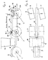
- the tractor vehicle has a front axle 1 with a single, central wheel 2 (or optionally two outer wheels 2, 2), a central axle 3 with wheels 4, 5 and a rear axle 6 with wheels 7, 8.
- 9 is the front frame (swing arm with a single front wheel) of the vehicle, 10 the driver's cabin, 11 the engine-transmission unit.
- the actual vehicle frame is shown at 12. This frame is lower than the upper edge of the wheels 4, 5 and 7, 8, and is a wasp waist frame or central tube frame, as can be seen in FIG. 2.
- a connection carrier 13 is arranged, which receives the frame 12 in a horizontal transverse bearing 14, so that a rotation indicated by the double arrow 15 around the bearing 14 is made possible.
- the axis of the transverse bearing 14 is offset or shifted in the direction of the driver's cab 10 or the front axle 1 with respect to the central axis 3.
- a drive connection between the axes 3 and 6 is indicated by 20. This connection is preferably a cardan shaft.
- a vertical double arrow 21 indicates the possibility of the up and down movement of the respective rear wheels 7, 8.
- the tractor vehicle 30 has a front axle 31 with a single central wheel 32 (or optionally two wheels 32, 32), a central axle 33 with wheels 34, 35 and a rear axle 36 with wheels 37, 38
- the continuous frame of the vehicle 30 is designated 39; it is designed in the front area as a swing arm 40 (with only one front wheel 32) and merges behind the motor-gear unit 41 into the middle and rear part as a device mounting frame 42, which is a central tubular frame or wasp waist frame.
- Center axis 33 and rear axle 36 are coupled to one another in terms of drive via a drive connection 43.
- a transverse bearing 44 is inserted into the drive connection 43 (either in the center or off-center); this transverse bearing 44 is received in a bearing block 45 rigidly attached to the frame 42, so that the axes 33 and 36 and the associated wheels 34, 35 and 37, 38 are arranged pivotably about the bearing point 44, ie the axis 33 is downward and the Axis 36 can move upwards accordingly; the extent of these movements can be determined by the selected gear ratio.
- the transverse bearing 48 is mounted directly in the frame 42, and the axes 33, 36 or the respective ends of the drive connection 33 are connected to the transverse bearing 48 via supports 46, 47. In this variant, the axes 33 and 36 can therefore also perform opposite vertical movements around the bearing 48.
- the wheels 34, 35, 37, 38 are designed to be steerable, and the two axes 32, 33 can be diagonally compensated for one another, that is to say, for example, oscillating.
Landscapes
- Engineering & Computer Science (AREA)
- Chemical & Material Sciences (AREA)
- Combustion & Propulsion (AREA)
- Transportation (AREA)
- Mechanical Engineering (AREA)
- Vehicle Body Suspensions (AREA)
- Body Structure For Vehicles (AREA)
- Arrangement And Driving Of Transmission Devices (AREA)
- Tires In General (AREA)
Claims (11)
- Tracteur agricole automoteur à trois essieux dont l'essieu avant (1) supporte une roue centrale dirigée (2), dont l'essieu intermédiaire (3) supporte deux roues (4, 5) et dont l'essieu arrière (6) supporte deux roues (7, 8), lesdites roues (2; 4, 5; 7, 8) étant garnies de pneus extra-larges et la largeur du véhicule étant plus ou moins égale à trois fois la largeur d'un pneu, la roue avant (2) étant conçue comme une roue dirigée et étant disposée de manière à tourner de maximum 90° vers la gauche et vers la droite par rapport à l'axe longitudinal du véhicule, la roue dirigée (2) étant logée par un côté dans un bras articulé (9), et le châssis (9, 12) du véhicule présentant, dans la zone de l'essieu intermédiaire et de l'essieu arrière (3, 6) une largeur beaucoup plus petite que la distance séparant les deux roues intermédiaires respectivement les roues arrières (3-4, 7-8), l'essieu arrière (6) présentant deux roues dirigées (7, 8) et l'essieu intermédiaire (3) présentant deux roues dirigées ou facultativement deux roues fixes (4, 5) garnies de pneus extra-larges, caractérisé en ce quea) l'essieu arrière (6) et l'essieu intermédiaire (3) sont accouplés l'un à l'autre par l'intermédiaire d'une commande mécanique (20);b) un porte-outils (12) formé d'un tube central s'étendant en continu depuis un point avant les roues intermédiaires (4, 5) jusqu'au delà des roues arrières (7, 8);c) le porte-outils (12) étant relié à l'essieu intermédiaire au moyen d'un palier transversal (14) horizontal de manière à pouvoir pivoter; etd) le palier transversal horizontal (14) étant disposé au-dessus de l'essieu intermédiaire et relié fixement avec le porte-outils (12).
- Tracteur automoteur selon la revendication 1, caractérisé en ce que le porte-outils (12) est disposé de manière à pouvoir basculer par rapport à l'essieu arrière au moyen d'un pivot longitudinal horizontal (17).
- Tracteur automoteur selon la revendication 1, caractérisé en ce que le porte-outils (12) est relié fixement avec l'essieu arrière (6).
- Tracteur automoteur selon la revendication 1, caractérisé en ce que le palier transversal horizontal (14) est décalé par rapport à l'essieu intermédiaire (3) dans la direction de l'essieu avant (1).
- Tracteur automoteur selon la revendication 1, caractérisé en ce que l'essieu avant (1) présente, à la place d'une seule roue centrale dirigée (2) deux roues dirigeables (2, 2) et en ce que l'essieu médian est rigide.
- Tracteur automoteur selon l'une ou l'autre des revendications précédentes, caractérisé en ce que la hauteur du porte-outils (12) formé d'un tube central est inférieure à celle des roues du véhicule (4, 5, 7, 8).
- Tracteur automoteur selon l'une ou l'autre des revendications précédentes, caractérisé en ce que la connexion de commande mécanique (20) est placée entre l'essieu intermédiaire (3) et l'essieu arrière (6) comme un arbre de transmission mécanique.
- Tracteur automoteur selon la revendication 1, caractérisé en ce que l'essieu médian (3) est flottant et l'essieu arrière rigide.
- Tracteur agricole automoteur à trois essieux dont l'essieu avant (31) supporte une roue centrale dirigée (32), dont l'essieu intermédiaire (33) supporte deux roues (34, 35) et dont l'essieu arrière (36) supporte deux roues (37, 38), lesdites roues étant garnies de pneus extra-larges et la largeur du véhicule étant plus ou moins égale à trois fois la largeur d'un pneu, la roue avant (32) étant conçue comme une roue dirigée et étant disposée de manière à tourner de maximum 90° vers la gauche et vers la droite par rapport à l'axe longitudinal du véhicule, la roue dirigée (32) étant logée par un côté sur un bras articulé (40), et le châssis (42) du véhicule présentant, dans la zone de l'essieu intermédiaire et de l'essieu arrière (33, 36) une largeur beaucoup plus petite que la distance séparant les deux roues intermédiaires respectivement les roues arrières l'essieu arrière (36) et l'essieu intermédiaire (33) présentant chacun des roues dirigées (37, 38, 34, 35), caractérisé, en ce quea) l'essieu arrière (36) et l'essieu intermédiaire (33) sont accouplés l'un avec l'autre au moyen d'une transmission mécanique (43),b) le châssis (39) est rigide sur toute sa longueur, etc) l'essieu intermédiaire et l'essieu arrière sont montés ensemble sur le porte-outils (42) de manière à pouvoir pivoter l'un par rapport à l'autre par l'intermédiaire d'un) palier transversal horizontal (44, 48).
- Tracteur automoteur selon la revendication 9, caractérisé en ce que le palier transversal (44) est situé dans la transmission mécanique (43) entre l'essieu intermédiaire et l'essieu arrière (33, 36) et est fixé au porte-outils (42) par le biais d'un support (45) et en ce que l'essieu intermédiaire et l'essieu arrière (33, 36) sont montés sur le porte-outils (42) de manière à pouvoir pivoter l'un par rapport à l'autre.
- Tracteur automoteur selon la revendication 9, caractérisé en ce que le roues (34, 35, 37, 38) de l'essieu intermédiaire (33) et de l'essieu arrière (36) sont montées de manière, par exemple de manière flottante, avec une compensation diagonale.
Applications Claiming Priority (2)
| Application Number | Priority Date | Filing Date | Title |
|---|---|---|---|
| DE4138502 | 1991-11-22 | ||
| DE4138502A DE4138502A1 (de) | 1991-11-22 | 1991-11-22 | Selbstfahrendes landwirtschaftliches dreiachsiges schlepperfahrzeug |
Publications (2)
| Publication Number | Publication Date |
|---|---|
| EP0543389A1 EP0543389A1 (fr) | 1993-05-26 |
| EP0543389B1 true EP0543389B1 (fr) | 1996-05-22 |
Family
ID=6445397
Family Applications (1)
| Application Number | Title | Priority Date | Filing Date |
|---|---|---|---|
| EP92119768A Expired - Lifetime EP0543389B1 (fr) | 1991-11-22 | 1992-11-20 | Tracteur agricole automoteur à trois essieux |
Country Status (2)
| Country | Link |
|---|---|
| EP (1) | EP0543389B1 (fr) |
| DE (2) | DE4138502A1 (fr) |
Families Citing this family (2)
| Publication number | Priority date | Publication date | Assignee | Title |
|---|---|---|---|---|
| DE19721130A1 (de) * | 1997-05-20 | 1998-11-26 | Claas Saulgau Gmbh | Ladewagen mit zwei oder mehr Achsen |
| DE102016105278B3 (de) * | 2016-03-22 | 2017-06-08 | Klaus Jourdan | Geschütztes Radfahrzeug |
Family Cites Families (7)
| Publication number | Priority date | Publication date | Assignee | Title |
|---|---|---|---|---|
| US2642144A (en) * | 1948-08-05 | 1953-06-16 | Jr William L Brewer | Tractor with six driven wheels |
| US3885932A (en) * | 1974-01-10 | 1975-05-27 | Super Products Corp | Dust filtration system |
| GB1578742A (en) * | 1976-02-24 | 1980-11-12 | Nat Res Dev | Peripatetic vehicles |
| GB2093415B (en) * | 1981-02-20 | 1985-06-26 | Pi Hsiang Wu | A multi-purpose agricultural power cart |
| FR2523045A1 (fr) * | 1982-03-12 | 1983-09-16 | Den Berg Christian Van | Engin automobile tout terrain a ossature porteuse a geometrie variable |
| DE3511647A1 (de) * | 1985-03-29 | 1986-10-02 | Horsch Maschinen GmbH, 8380 Landau | Selbstfahrendes landwirtschaftliches schlepperfahrzeug |
| DE9109012U1 (de) * | 1991-07-22 | 1991-11-07 | FSB-Oskar Lauer GmbH, 6124 Beerfelden | Vorrichtung zum Lenken eines 3-Achsigen-Transportfahrzeuges |
-
1991
- 1991-11-22 DE DE4138502A patent/DE4138502A1/de not_active Withdrawn
-
1992
- 1992-11-20 EP EP92119768A patent/EP0543389B1/fr not_active Expired - Lifetime
- 1992-11-20 DE DE59206359T patent/DE59206359D1/de not_active Expired - Fee Related
Also Published As
| Publication number | Publication date |
|---|---|
| DE59206359D1 (de) | 1996-06-27 |
| DE4138502A1 (de) | 1993-05-27 |
| EP0543389A1 (fr) | 1993-05-26 |
Similar Documents
| Publication | Publication Date | Title |
|---|---|---|
| EP2192026B2 (fr) | Machine de traction agricole | |
| DE3826930C2 (de) | Radaufhängungssystem | |
| DE1130308B (de) | Landwirtschaftlicher Schlepper mit einem Gestell und zwei lenkbaren Laufraedern | |
| DE1932243A1 (de) | Lenkeinrichtung fuer Anhaenger | |
| DE2622736A1 (de) | Aufhaengemechnismus fuer ein vierraedriges fahrzeug | |
| DE4444115C2 (de) | Mehrspuriges Leichtfahrzeug | |
| EP0678443B1 (fr) | Train de roulement, notamment pour machines de travail mobiles et véhicules | |
| DE68906782T2 (de) | Kraft- oder schleppfahrzeug mit unabhängigen doppelrädern. | |
| EP2660130A1 (fr) | Véhicule à deux voies doté de chenilles | |
| EP0331070B1 (fr) | Véhicule agricole polyvalent | |
| EP0011881B1 (fr) | Autobus à carrosserie articulée | |
| EP0350008A2 (fr) | Machine pour travailler le sol | |
| EP0543389A1 (fr) | Tracteur agricole automoteur à trois essieux | |
| DE2603284A1 (de) | Schlepper | |
| DE69105723T2 (de) | Achssystem in einem transportfahrzeug. | |
| WO1992006753A1 (fr) | Planche a roulettes | |
| EP0196643A2 (fr) | Tracteur agricole tricycle automoteur | |
| DE3713474A1 (de) | Heuwerbungsmaschine | |
| DE69900045T2 (de) | Landwirtschaftstraktor mit schnellem Wendemechanismus und Verfahren | |
| DD243677A1 (de) | Verstelleinrichtung fuer radabweiser an fahrzeugen mit kippaufbauten | |
| DE3330965A1 (de) | Schlepper | |
| DE69817509T2 (de) | Gefederte Streuvorrichtung | |
| DE3330932A1 (de) | Schlepper, insbesondere fuer die landwirtschaft | |
| DE202008000162U1 (de) | Zugwagen, insbesondere für den Pferdesport | |
| DE2920308A1 (de) | Lenkung fuer einen lastkraftwagen oder einen omnibus |
Legal Events
| Date | Code | Title | Description |
|---|---|---|---|
| PUAI | Public reference made under article 153(3) epc to a published international application that has entered the european phase |
Free format text: ORIGINAL CODE: 0009012 |
|
| AK | Designated contracting states |
Kind code of ref document: A1 Designated state(s): BE DE DK FR GB NL |
|
| 17P | Request for examination filed |
Effective date: 19930901 |
|
| 17Q | First examination report despatched |
Effective date: 19941222 |
|
| GRAH | Despatch of communication of intention to grant a patent |
Free format text: ORIGINAL CODE: EPIDOS IGRA |
|
| GRAA | (expected) grant |
Free format text: ORIGINAL CODE: 0009210 |
|
| AK | Designated contracting states |
Kind code of ref document: B1 Designated state(s): BE DE DK FR GB NL |
|
| PG25 | Lapsed in a contracting state [announced via postgrant information from national office to epo] |
Ref country code: NL Free format text: LAPSE BECAUSE OF FAILURE TO SUBMIT A TRANSLATION OF THE DESCRIPTION OR TO PAY THE FEE WITHIN THE PRESCRIBED TIME-LIMIT Effective date: 19960522 Ref country code: FR Effective date: 19960522 Ref country code: DK Effective date: 19960522 Ref country code: BE Effective date: 19960522 |
|
| REF | Corresponds to: |
Ref document number: 59206359 Country of ref document: DE Date of ref document: 19960627 |
|
| GBT | Gb: translation of ep patent filed (gb section 77(6)(a)/1977) |
Effective date: 19960902 |
|
| EN | Fr: translation not filed | ||
| EN | Fr: translation not filed | ||
| NLV1 | Nl: lapsed or annulled due to failure to fulfill the requirements of art. 29p and 29m of the patents act | ||
| PLBE | No opposition filed within time limit |
Free format text: ORIGINAL CODE: 0009261 |
|
| STAA | Information on the status of an ep patent application or granted ep patent |
Free format text: STATUS: NO OPPOSITION FILED WITHIN TIME LIMIT |
|
| 26N | No opposition filed | ||
| PGFP | Annual fee paid to national office [announced via postgrant information from national office to epo] |
Ref country code: GB Payment date: 20011121 Year of fee payment: 10 |
|
| PGFP | Annual fee paid to national office [announced via postgrant information from national office to epo] |
Ref country code: DE Payment date: 20011220 Year of fee payment: 10 |
|
| REG | Reference to a national code |
Ref country code: GB Ref legal event code: IF02 |
|
| PG25 | Lapsed in a contracting state [announced via postgrant information from national office to epo] |
Ref country code: GB Free format text: LAPSE BECAUSE OF NON-PAYMENT OF DUE FEES Effective date: 20021120 |
|
| PG25 | Lapsed in a contracting state [announced via postgrant information from national office to epo] |
Ref country code: DE Free format text: LAPSE BECAUSE OF NON-PAYMENT OF DUE FEES Effective date: 20030603 |
|
| GBPC | Gb: european patent ceased through non-payment of renewal fee |