EP0543577A2 - Ensemble d'essai de la perte locale d'une fibre optique - Google Patents
Ensemble d'essai de la perte locale d'une fibre optique Download PDFInfo
- Publication number
- EP0543577A2 EP0543577A2 EP92310382A EP92310382A EP0543577A2 EP 0543577 A2 EP0543577 A2 EP 0543577A2 EP 92310382 A EP92310382 A EP 92310382A EP 92310382 A EP92310382 A EP 92310382A EP 0543577 A2 EP0543577 A2 EP 0543577A2
- Authority
- EP
- European Patent Office
- Prior art keywords
- signal
- optical
- fault
- optical fiber
- loss
- Prior art date
- Legal status (The legal status is an assumption and is not a legal conclusion. Google has not performed a legal analysis and makes no representation as to the accuracy of the status listed.)
- Withdrawn
Links
Images


Classifications
-
- G—PHYSICS
- G01—MEASURING; TESTING
- G01M—TESTING STATIC OR DYNAMIC BALANCE OF MACHINES OR STRUCTURES; TESTING OF STRUCTURES OR APPARATUS, NOT OTHERWISE PROVIDED FOR
- G01M11/00—Testing of optical apparatus; Testing structures by optical methods not otherwise provided for
- G01M11/30—Testing of optical devices, constituted by fibre optics or optical waveguides
- G01M11/33—Testing of optical devices, constituted by fibre optics or optical waveguides with a light emitter being disposed at one fibre or waveguide end-face, and a light receiver at the other end-face
- G01M11/333—Testing of optical devices, constituted by fibre optics or optical waveguides with a light emitter being disposed at one fibre or waveguide end-face, and a light receiver at the other end-face using modulated input signals
-
- G—PHYSICS
- G01—MEASURING; TESTING
- G01M—TESTING STATIC OR DYNAMIC BALANCE OF MACHINES OR STRUCTURES; TESTING OF STRUCTURES OR APPARATUS, NOT OTHERWISE PROVIDED FOR
- G01M11/00—Testing of optical apparatus; Testing structures by optical methods not otherwise provided for
- G01M11/30—Testing of optical devices, constituted by fibre optics or optical waveguides
- G01M11/35—Testing of optical devices, constituted by fibre optics or optical waveguides in which light is transversely coupled into or out of the fibre or waveguide, e.g. using integrating spheres
Definitions
- the present invention generally relates to devices for testing the transmission of light signals through optical fibers, and more particularly to a test set providing accurate measurement of signal attenuation across a fault, such as a splice, in an optical fiber.
- optical fiber optic cables have replaced traditional copper wire as the preferred medium for telecommunications.
- optical fibers have certain advantages over copper wire, they are still subject to attenuation of the light signals travelling therein, since there can never be 100% transmission of light through these fibers. Accordingly, it is imperative to provide optical fibers which have the minimum attenuation possible, in order to maximize the length of fiber which may carry a signal without the addition of expensive repeaters or amplifiers.
- faults may take the form of a kinks or microbends in the fiber (which allow light to escape through the buffer coating of the fiber), but.the greatest signal loss typically occurs at connections, or splices, between two fiber ends, which induce Fresnel reflections of the transmitted signal at the fiber end faces. Such reflections may be minimized by proper alignment of the fibers and the use of index matching gels, but there is always a detectable signal loss. It is necessary to so splice fibers together in order to provide extremely long fiber paths, requiring several cable sections, or to repair a break or other fault in a fiber. This is accomplished through the use of a variety of disengagable connectors, or permanent splices formed by bonding, fusion welding, or mechanical clamping.
- an OTDR optical time domain reflectometer
- a light source such as a pulsed laser diode
- an optical coupler including a beam-splitter, connecting the light source to the near end of the fiber under test (FUT); and a photodetector positioned adjacent the beam splitter.
- FUT fiber under test
- a photodetector positioned adjacent the beam splitter.
- OTDR's are extremely useful in the location of multiple faults, they have three clear disadvantages with regard to measurement of specific faults, e.g., splices.
- splices it is necessary to connect the OTDR to the terminal end of the fiber in order to inject and detect the test signal and reflections. This means that the OTDR user must be remote from the splice location, usually by several kilometers.
- the measurements of splice loss are not as accurate as they could be if the loss was measured closer to the splice.
- the splice loss cannot be quickly determined after completion of the splice, but rather the technician must move to the remote terminal site in order to set up the OTDR. If the just installed splice has an unacceptable loss, the technician must return to the splice location and repeat the entire effort, unless two technicians are involved which is clearly undesirable.
- Another local loss test system is manufactured by American Telephone and Telephone, and comprises two units, a light injection module which utilizes microbending to place the test signal in the fiber, and a splice alignment/measurement module which provides a readout of the attenuation of the signal across a splice.
- the values of certain parameters regarding loss measurement are preprogrammed into the memory of the measurement module, which consequently can provide an estimate of the splice loss.
- Such a system would preferably include a measurement module which is not strictly limited to use with one particular signal source, and which is self-calibrating.
- a local loss test set comprising a receiver unit having means for withdrawing a light signal, memory means for storing first and second signal measurements, processing means for comparing the values of the signal measurements, and means for displaying the result of said comparison.
- the receiver thus may be used to take the first signal measurement on one side of the splice (i.e., between the signal source and the splice), and compare that to the second measurement which is taken from the other side of the splice. By comparing splice attenuation against a contemporaneous measurement of initial signal strength, the best possible measurement of actual splice loss may be achieved.
- a light withdrawal means which extracts the light in a consistent and repeatable manner, at least for a given type of fiber.
- the preferred means includes a piston terminating in a head having a convex surface and a groove formed in the surface which catches the fiber under test and clamps it against a concave silica form.
- a light detector is attached to the form at an appropriate location and orientation to detect the signal escaping at the microbend of the fiber.
- the fiber receiving groove in the piston head, along with springs (or other biasing means) controlling the piston provide a consistent clamping force to optimize calibration of the loss signal to the reference signal.
- the receiver of the present invention may be used with several different types of light sources, certain economies in manufacture may be achieved by designing the receiver to cooperate with the characteristics of a particular transmitter (light signal source).
- the receiver uses a low cost photodetector having a relatively high noise current; the effects of the noise, however, are minimized by using a transmitter which has laser diodes, providing more power than, e.g., light-emitting diodes, and by filtering the measured signal according to the modulation of the laser source.
- the electronic components of the receiver and transmitter may be combined in a base unit, with their mechanical components located in separate, tethered units.
- a second transmitter may be employed, provided the receiver is bidirectional, to further improve the accuracy of the loss measurement.
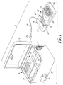
- the local loss test set of the present invention basically comprises a receiver 2 which, as explained further below, preferably takes the form of a base unit 4 housing the electronic components of receiver 2 , and a remote unit 6 housing the optomechanical components of receiver 2 .
- Base unit 4 is formed of a body 8 having a cover 10 , forming a weatherproof container for base unit 4 , and further includes a user interface panel 12 which is described below in conjunction with Figure 5.
- Body 8 and cover 10 may be constructed of any durable material, preferably a polymer such as polycarbonite.
- the various electronic components of receiver 2 are located on printed circuit boards 14 within body 8.
- a battery 16 is placed within body 8 .
- Body 8 may also be provided with a compartment 17 for storing remote unit 6 , or other items such as the transmitter unit discussed further below.
- Remote unit 6 generally comprises a housing 18 having a fiber receiving slot 20 and a fiber clamp actuation plate or slide 22 .
- a set of wires 24 terminating in a coaxial connector 28 emanates from a hole in housing 18 .
- Wires 24 are preferably about 75 cm long, allowing relatively free movement of remote unit 6 .
- housing 18 may vary considerably, remote unit 6 is preferably hand-held. Accordingly, exemplary dimensions of housing 18 are 3 cm x 12 cm x 1.2 cm. Housing 18 may also be constructed of the same polycarbonite material used in forming body 8 , or any other durable material such as anodized aluminum. Plate 22 slides between the open position illustrated in Figure 1, and the closed position illustrated in Figure 2, resulting in the clamping of a fiber which has been inserted in slot 20 .
- Housing 18 is preferably constructed from a base 30 , a cover 32 , a slide jacket 34 , and a slide support plate 36 . These parts may be appropriately fastened together by any convenient means such as screws.
- the edges of slide plate 22 extend into notches 38 formed in the legs 40 of slide jacket 34 whereby plate 22 may slide freely within jacket 34 .
- Slide 22 preferably has a plurality of surface features such as recesses 42 which facilitate manual sliding. A mound or knob may optionally be formed in slide 22 .
- Base 30 of housing 18 has several cavities, channels and bosses formed therein for receiving the mechanical and optical components of remote unit 6 . These features may be formed by integrally molding them into base 30 , or by attaching insert members.
- One channel 44 serves to guide slide blocks 46 which are fixed to slide plate 22 by screws 48 .
- a sliding shaft 50 is slidably interposed between slide blocks 46 , and is further coupled to them by means of two springs 52 . As explained below, these springs control the pressure which is ultimately applied to the FUT.
- Springs 52 are attached at one end to pins 54 of slide blocks 46 , and at the other end to pin 56 which passes through a hole in the proximate end of shaft 50 .
- Pins 54 also receive another set of springs 58 attached to a rod 60 , near the bottom portion of base 30 , which unites two locating arms 62 .
- Locating arms 62 terminate near slot 20 in a plurality of alignment fingers 64 .
- Locating arms 62 are biased toward the bottom portion of base 30 by springs 63 which are attached to pegs 65 formed integrally with base 30 .
- a piston rod 66 is attached to the distal end of shaft 50 , and generally aligned with shaft 50 .
- Rod 66 terminates in a generally cylindrical piston head 68 , having a radius of about 2.9 mm.
- Adjacent to piston head 68 , opposite rod 66 is an optically receptive form 70 , preferably formed of silica (glass).
- the surface of form 70 proximate piston head 68 is concave whereby, when an optical fiber is clamped between head 68 and form 70 , it is bent or curved slightly.
- the radius of curvature of the concave surface is about 3.0 mm.
- One surface of form 70 is at an oblique angle (preferably about 67.5°) with respect to the tangent formed between head 68 and form 70 , and a photodetector 72 is placed against this surface whereby a portion of the light escaping from a clamped fiber will be transmitted to detector 72 .
- Detector 72 is connected to wires 24 , which pass through and are attached to a spring 74 to provide strain relief for wires 24 .
- remote unit 6 begins with the placement of a portion of the FUT into slot 20 .
- a label 76 has an arrow to indicate the anticipated direction of travel of the test signal. In this regard, means may be provided to detect a signal from either direction (as discussed further below), but care must be taken if there is only one direction of travel of the test signal since the fault (splice) is only on one side of receiver 2 .
- Slot 20 is located so as to place the fiber between piston head 68 and form 70 .
- slide plate 22 is biased toward the bottom portion of housing 18 by the combined action of springs 58 and 63 .
- the spring constant of springs 58 should be greater than that of springs 63 . Due to the abutment of the ends of slide blocks 46 against pin 56 , shaft 50 and piston head 68 are also in the retracted position. Locating arms are additionally retracted due to springs 63 .
- Piston head 68 preferably has a circumferential groove is formed therein for receiving the FUT. Use of such a groove, combined with the precise clamping force provided by spring 52 , imparts exceptional consistency and repeatability with regard to multiple clampings and measurements on a given fiber.
- the groove is approximately 250 ⁇ m deep.
- a leaf spring 80 lies in a channel formed in shaft 50 . The hump in leaf spring 80 contacts the inner surface of slide jacket 34 , restricting transverse movement of shaft 50 and piston head 68 to assure that the circumferential groove in piston head 68 is always positioned properly.
- Wires 24 then convey the measured signal to base unit 4 by means of connector 28 which mates with receptacle 78 in base unit 4 .
- the electrical signal is then processed by the electronic components depicted in block form in Figure 3.
- the electrical signal is first conditioned by an amplifier 82 and a bandpass filter 84 .
- the conditioned signal is converted from analog-to-digital value by A/D converter 86 .
- the digital value is recorded by a processor 88 (such as the MC68000 processor sold by Motorola, Inc., of Schaumberg, Illinois) and stored in random-access memory (RAM) 90 .
- Amplifier 82 may be range selectable by processor 88 in order to optimize the electrical signal at the input of A/D converter 86 . This provides the bit resolution necessary to achieve an accuracy of 0.1 dB or better in loss measurement.
- Read-only memory 92 is provided to store the program instructions for processor 88 , which is also connected to a display 94 and a keypad 96 .
- keypad 96 may be used to control processor 88 whereby a first, reference measurement on the side of the splice toward the signal source may be stored in RAM 90 , and a second, loss measurement on the opposite side of the splice may be compared with the reference measurement, yielding an accurate splice loss value.
- receiver 2 may be used with essentially any signal source, e.g., a source which injects a test signal at the terminal end of the fiber, or one which injects light locally through microbending of the fiber. It will further be appreciated, however, that certain economies in the manufacture of receiver 2 may be achieved by designing a transmitter to complement the specifications of receiver 2 .
- the electronic components of such a transmitter are housed in body 8, and the mechanical components are housed in a remote transmitter unit which is nearly identical to remote unit 6 of receiver 2 .
- the transmitter unit 100 of the present invention may be explained with reference to each of the foregoing figures, in which details of the optional transmitter are indicated in dashed lines.
- transmitter unit 100 includes all of the structural features of remote unit 6 except for photodetector 72 and wires 74 In lieu of those elements, transmitter unit 100 has an optical fiber 102 terminated at its distal end in an optical connector 104 .
- a cover 106 is preferably provided for connector 104.
- the proximate end of fiber 102 terminates in a light-transmitting element 108 , such as the SELFOCTM collimator sold by Nippon Sheet Glass Company of Tokyo, Japan.
- Element 108 abuts one side of form 70 whereby, when an optical signal is injected into fiber 102 via connector 104 , it passes through element 108 , into form 70 , and then into the FUT held between form 70 and piston head 68 .
- transmitter unit 100 and remote unit 6 appear nearly identical, it is desirable to have fiber 102 emanate through another hole 110 in the opposite side of body 8 with respect to the hole for wires 24 .
- the only other difference between remote unit 6 and transmitter unit 100 is the writing on label 76 to indicate "TRANSMITTER” rather than "RECEIVER.”
- Connector 104 of fiber 102 may be connected to any appropriate signal source but, as mentioned above, the source is preferably contained within base unit 4 , and connector 104 is connected to one of the optical ports 112 provided on base unit 4 .
- optical port 112 is optically coupled to a light source such as a laser diode 114 .
- Laser diode 114 is connected to a driver 116 which is regulated by a modulator 118 , which in turn is controlled by processor 88 .
- transmitter 100 and its associated electronic components are not essential to operation of receiver 2, they may be selected to cooperate with the various components of receiver 2 .
- receiver 2 could utilize a sensitive photodetector in which case a high-power light-emitting diode (LED) could be used in lieu of the more expensive laser diode.
- the stronger power laser diode such as that sold by MRV of Chatsworth, California, under part number MR-LDSP010) is used which complements the use of a low cost photodetector 72 , such as the germanium detector sold by EG&G Judson of Montgomeryville, Pennsylvania, under part number J1630-R30M.
- bandpass filter 84 which is tuned to the frequency of modulator 118 (preferably 1 kHz). Due to the fact that loss measurements with this system are based on the concurrent power level of the injected light, it is not necessary to provide a transmitter which has a consistent output or coupling efficiency, i.e., accurate repeatability in the transmitter is not required.
- Laser diode 114 may produce light of any wavelength, preferably 1300 nm; its spectral width is not critical.
- the aforementioned germanium detector has an acceptable spectral response in the range of 800 nm to 1800 nm.
- FIG. 4 depicts user interface panel 12 , comprising display 94 and keypad 96 , including input keys 120 , 122 and 124 .
- Display 94 is preferably a liquid crystal display (LCD), and it is understood that the various fields shown in Figure 4 are not always displayed, e.g., the words "Battery Low” will appear on display 94 only when a low power state is detected by processor 88 .
- Base unit 4 is powered up by hitting on/off key 120 , and the user is immediately prompted to obtain a reference measurement (using remote unit 6 ) by the word “Reference" being flashed on display 94 .
- option/loss key 124 Prior to taking measurements, however, certain variables may be selected by pushing option/loss key 124 . The user will then be prompted to enter appropriate values for passing and failing thresholds. For example, when option/loss key 124 is depressed for about five seconds, the words “Threshold” and "Pass” will appear on display 94 , and a minimum threshold value such as 0.3 dB will appear in the numeric field. Higher threshold values are sequentially displayed (in increments of, e.g., 0.05 dB) by continued depression of option/loss key 124. When the proper value is displayed, enter/reference key 122 is pushed. The word “Pass” will then be extinguished from display 94 , and "Fail” will appear. The same procedure is used to select the threshold for an unacceptable splice loss. Default settings of 0.5 dB and 0.7 dB for passing and failing, respectively, may be provided in the program instructions stored in ROM 92 .
- the user clamps transmitter unit 100 onto a portion of the FUT. It is preferable to clamp transmitter unit 100 at least 30 cm away from remote unit 6 in order to avoid cladding mode signals which might lead to false measurements.
- the arrow on label 76 of transmitter unit 100 should point toward the splice or other fault to be tested. Remote unit 6 is then clamped onto the FUT between transmitter 100 and the fault (with the arrow on label 76 aligned with the arrow on the transmitter), and enter/reference key 122 is depressed.
- the word "Test” appears briefly on display 94 as base unit 4 executes diagnostics and measures the reference signal; several measurements may be made and averaged to yield the value of the reference signal.
- Base unit also confirms that the power level measured by receiver 2 is acceptable (e.g., at least one nanowatt). If not, the words “Low Signal” appear on display 94 , and the word “Reference” begins flashing again, prompting the user to reclamp one or both of the transmitter and remote units 100 and 6 .
- the word "Reference” is extinguished from display 94 , and the user then moves remote unit 6 to the side of the fault opposite transmitter unit 100 .
- Option/loss key 124 is depressed, and a loss measurement is made. Again, several successive measurements may be automatically taken and averaged to yield the value of the loss signal. This value is then compared to the value of the reference signal. If the difference (in decibels) is lower than the pass threshold, the word “Pass” appears on display 94; if the difference is greater than the fail threshold, the word “Fail” appears. If the difference is between the two thresholds, then the word “Repeat” appears, and the word “Reference” will begin flashing again to prompt the user to repeat the measurements. In any case, the loss is also displayed in the numeric field of display 94 . This entire process is very simple and performed relatively quickly, yet yields a highly accurate measurement of actual signal loss through the splice.
- transmitter unit 100 could include the light source (laser diode), and possibly other components such as the driver and modulator, with a wire cable connected to base unit 4 rather than the optical cable 102 .
- remote receiver 6 could have an optical fiber connected to base unit 4 for relaying the signal captured from the FUT to a photodetector located within base unit 4 .
- Remote unit 6 could even be set up as a wireless remote unit if a separate power supply were provided in it along with means for electromagnetically transmitting the detected signal to base unit 4 .
- a further alternative embodiment contemplates the use of two transmitters and a bidirectional receiver.
- Each of the transmitters is essentially identical to transmitter unit 100 ; they are clamped on either side of the fault to be tested, with the test signals injected in a direction toward the fault (the arrows on the transmitter labels may be oppositely directed to facilitate proper orientation).
- Base unit 4 would contain two sets of laser diodes, drivers and modulators, or a beam splitting device may be employed to provide signals to the two optical fibers connecting base unit 4 to the transmitters.
- the bidirectional receiver is also essentially identical to remote unit 6 except for the provision of an additional photodetector 71 and its corresponding wire pair 26 (illustrated in Figure 2).
- Base unit 4 could contain a duplicate set of the amplifier, filter and A/D converter used to condition the electrical signals, or the signals could be multiplexed. In this manner, when the bidirectional receiver is clamped to the FUT (on either side of the fault), two measurements are taken, one being a first reference signal and the other being a first loss signal. The receiver is then clamped to the other side of the fault (maintaining the same orientation with respect to the fiber axis), and a second reference signal and second loss signal are taken.
- Processor 88 compares the first reference signal to the second loss signal, and the second reference signal to the first loss signal, providing two relative loss values for each direction of travel through the fault. These values may be averaged to yield an extremely accurate loss measurement which is then displayed as discussed above. Finally, the accuracy of such a redundant system could further be enhanced by the use of two different wavelengths of light in the injected signals.
Landscapes
- Physics & Mathematics (AREA)
- Optics & Photonics (AREA)
- Chemical & Material Sciences (AREA)
- Analytical Chemistry (AREA)
- General Physics & Mathematics (AREA)
- Testing Of Optical Devices Or Fibers (AREA)
- Arrangements For Transmission Of Measured Signals (AREA)
- Light Guides In General And Applications Therefor (AREA)
Applications Claiming Priority (2)
| Application Number | Priority Date | Filing Date | Title |
|---|---|---|---|
| US79407591A | 1991-11-19 | 1991-11-19 | |
| US794075 | 1991-11-19 |
Publications (2)
| Publication Number | Publication Date |
|---|---|
| EP0543577A2 true EP0543577A2 (fr) | 1993-05-26 |
| EP0543577A3 EP0543577A3 (fr) | 1993-06-09 |
Family
ID=25161621
Family Applications (1)
| Application Number | Title | Priority Date | Filing Date |
|---|---|---|---|
| EP19920310382 Withdrawn EP0543577A3 (fr) | 1991-11-19 | 1992-11-13 | Ensemble d'essai de la perte locale d'une fibre optique |
Country Status (3)
| Country | Link |
|---|---|
| EP (1) | EP0543577A3 (fr) |
| JP (1) | JPH05231989A (fr) |
| CA (1) | CA2082231A1 (fr) |
Cited By (6)
| Publication number | Priority date | Publication date | Assignee | Title |
|---|---|---|---|---|
| WO1995006865A1 (fr) * | 1993-08-30 | 1995-03-09 | Siemens Aktiengesellschaft | Procede et dispositif pour le controle des proprietes d'au moins une epissure d'au moins un guide d'ondes lumineuses |
| WO1996035931A1 (fr) * | 1995-05-11 | 1996-11-14 | Poole Craig D | Dispositif optique de mesure de puissance utilisant un circuit a faible courant |
| US6917750B2 (en) | 2003-05-29 | 2005-07-12 | 3M Innovative Properties Company | System and method for characterizing optical devices |
| US8756031B2 (en) | 2010-07-13 | 2014-06-17 | International Business Machines Corporation | Matched filter testing of data transmission cables |
| US9360392B2 (en) | 2013-06-28 | 2016-06-07 | Corning Cable Systems Llc | Calibration of optical time domain reflectometry optical loss measurement in optical fibers having potentially dissimilar light backscattering efficiencies |
| WO2022018670A1 (fr) * | 2020-07-24 | 2022-01-27 | Nos Technology - Concepção, Construção E Gestão De Redes De Comunicações, S.A. | Surveillance de trafic non intrusive dans des réseaux de fibres optiques |
Families Citing this family (2)
| Publication number | Priority date | Publication date | Assignee | Title |
|---|---|---|---|---|
| JP5992482B2 (ja) * | 2014-10-07 | 2016-09-14 | アンリツ株式会社 | 芯線検査装置および芯線検査方法 |
| CN115524096B (zh) * | 2022-10-26 | 2026-02-03 | 桂林聚联科技有限公司 | 一种光纤线路衰减测量方法、装置、电子设备及存储介质 |
Family Cites Families (4)
| Publication number | Priority date | Publication date | Assignee | Title |
|---|---|---|---|---|
| JPS5483458A (en) * | 1977-12-15 | 1979-07-03 | Nippon Telegr & Teleph Corp <Ntt> | Measuring method of connection loss of optical fibers |
| CA1213057A (fr) * | 1984-10-25 | 1986-10-21 | Northern Telecom Limited | Methode et instrument de mesure de la dissipation absolue au site d'accouplement de fibres |
| JPS6238341A (ja) * | 1985-08-14 | 1987-02-19 | Mitsubishi Rayon Co Ltd | 光学繊維の光伝送損失測定方法及び装置 |
| DE3828604A1 (de) * | 1988-08-23 | 1990-03-01 | Siemens Ag | Verfahren und einrichtung zur messung der optischen daempfung eines optischen mediums |
-
1992
- 1992-11-05 CA CA 2082231 patent/CA2082231A1/fr not_active Abandoned
- 1992-11-13 EP EP19920310382 patent/EP0543577A3/fr not_active Withdrawn
- 1992-11-18 JP JP30862392A patent/JPH05231989A/ja active Pending
Cited By (7)
| Publication number | Priority date | Publication date | Assignee | Title |
|---|---|---|---|---|
| WO1995006865A1 (fr) * | 1993-08-30 | 1995-03-09 | Siemens Aktiengesellschaft | Procede et dispositif pour le controle des proprietes d'au moins une epissure d'au moins un guide d'ondes lumineuses |
| US5680206A (en) * | 1993-08-30 | 1997-10-21 | Siemens Aktiengesellschaft | Method and device for testing the properties of at least one splice in at least one optical waveguide |
| WO1996035931A1 (fr) * | 1995-05-11 | 1996-11-14 | Poole Craig D | Dispositif optique de mesure de puissance utilisant un circuit a faible courant |
| US6917750B2 (en) | 2003-05-29 | 2005-07-12 | 3M Innovative Properties Company | System and method for characterizing optical devices |
| US8756031B2 (en) | 2010-07-13 | 2014-06-17 | International Business Machines Corporation | Matched filter testing of data transmission cables |
| US9360392B2 (en) | 2013-06-28 | 2016-06-07 | Corning Cable Systems Llc | Calibration of optical time domain reflectometry optical loss measurement in optical fibers having potentially dissimilar light backscattering efficiencies |
| WO2022018670A1 (fr) * | 2020-07-24 | 2022-01-27 | Nos Technology - Concepção, Construção E Gestão De Redes De Comunicações, S.A. | Surveillance de trafic non intrusive dans des réseaux de fibres optiques |
Also Published As
| Publication number | Publication date |
|---|---|
| EP0543577A3 (fr) | 1993-06-09 |
| CA2082231A1 (fr) | 1993-05-20 |
| JPH05231989A (ja) | 1993-09-07 |
Similar Documents
| Publication | Publication Date | Title |
|---|---|---|
| EP1977279B1 (fr) | Outil d'installation équipé d'un indicateur d'erreur visuel intégré pour raccord mécanique montable sur place | |
| JP5199883B2 (ja) | 許容スプライス成端接続を検証する装置及び方法 | |
| US9036991B2 (en) | Optical transceiver having an OTDR mode, and a method of obtaining test data for testing an optical fiber | |
| US6956643B2 (en) | Apparatus and method for testing optical transceivers | |
| WO2015031223A1 (fr) | Système d'essai pour vérifier une connexion par épissage entre un connecteur de fibre optique et une ou plusieurs fibres optiques | |
| US5315365A (en) | Macrobend splice loss tester for fiber optic splices with silicon gel cushion on optical coupling blocks | |
| US7192195B2 (en) | Methods and apparatus for estimating optical insertion loss | |
| US20180058981A1 (en) | Devices, systems, and methods for checking the continuity of at least one splice within a fiber optic connector | |
| WO2014123596A2 (fr) | Procédés et appareil de test et de terminaison d'épissures mécaniques de fibres optiques | |
| CA2104834C (fr) | Systeme de verification d'epissure optique | |
| EP0543577A2 (fr) | Ensemble d'essai de la perte locale d'une fibre optique | |
| EP0591340B1 (fr) | Methode de transfert de lumiere | |
| MX2008007660A (es) | Aparato y metodos para verificar una terminacion de empalme aceptable |
Legal Events
| Date | Code | Title | Description |
|---|---|---|---|
| PUAI | Public reference made under article 153(3) epc to a published international application that has entered the european phase |
Free format text: ORIGINAL CODE: 0009012 |
|
| PUAL | Search report despatched |
Free format text: ORIGINAL CODE: 0009013 |
|
| AK | Designated contracting states |
Kind code of ref document: A2 Designated state(s): DE ES FR GB IT NL |
|
| AK | Designated contracting states |
Kind code of ref document: A3 Designated state(s): DE ES FR GB IT NL |
|
| 18D | Application deemed to be withdrawn |
Effective date: 19931210 |