EP0543696A1 - Vorrichtung für eine Türe mit Deckplatte - Google Patents
Vorrichtung für eine Türe mit Deckplatte Download PDFInfo
- Publication number
- EP0543696A1 EP0543696A1 EP92402970A EP92402970A EP0543696A1 EP 0543696 A1 EP0543696 A1 EP 0543696A1 EP 92402970 A EP92402970 A EP 92402970A EP 92402970 A EP92402970 A EP 92402970A EP 0543696 A1 EP0543696 A1 EP 0543696A1
- Authority
- EP
- European Patent Office
- Prior art keywords
- door
- panel
- covering
- front face
- tongue
- Prior art date
- Legal status (The legal status is an assumption and is not a legal conclusion. Google has not performed a legal analysis and makes no representation as to the accuracy of the status listed.)
- Granted
Links
- 238000005253 cladding Methods 0.000 abstract description 3
- 210000002105 tongue Anatomy 0.000 description 30
- 238000005553 drilling Methods 0.000 description 1
- 230000003100 immobilizing effect Effects 0.000 description 1
- 210000000056 organ Anatomy 0.000 description 1
Images


Classifications
-
- A—HUMAN NECESSITIES
- A47—FURNITURE; DOMESTIC ARTICLES OR APPLIANCES; COFFEE MILLS; SPICE MILLS; SUCTION CLEANERS IN GENERAL
- A47L—DOMESTIC WASHING OR CLEANING; SUCTION CLEANERS IN GENERAL
- A47L15/00—Washing or rinsing machines for crockery or tableware
- A47L15/42—Details
- A47L15/4251—Details of the casing
- A47L15/4257—Details of the loading door
- A47L15/4265—Arrangements of door covering/decoration panels or plinths, e.g. for integrated dishwashers
Definitions
- the present invention relates to a door appliance provided with a covering panel.
- This appliance can be a dishwasher or any other household appliance.
- a household appliance such as a dishwasher can thus have a wooden cladding panel on the front, for example, surmounted by a control panel.
- the front face of the covering panel is in the same plane as the front of the adjacent piece of furniture.
- a dishwasher generally comprises a tub closed by a front door pivoting around a horizontal axis located at the lower edge of the door.
- the door is designed to be vertical in the closed position and horizontal in the open position. In the open position, it serves as a slide and support for a dish basket.
- the basket is pulled out of the tank of the appliance to fill it, empty it or when you need access to the organs located in the tank.
- the covering panel covers the front face of the door and is fixed to the door.
- a known system for fixing the covering panel provides for the use of two types of fixing elements.
- first fastening elements are secured to one side of the covering panel in its lower part. These first elements end on the other side with a tongue which is introduced into an opening carried by the front face of the door.
- the first elements join the covering panel and the door, in horizontal relative translation from front to back and from back to front, and in relative vertical translation in a first direction.
- Second fastening elements generally two in number, are also used. They each have the shape of a square with a first wing integral with the covering panel in its upper part, and a second wing engaging between the front face and the rear face of the door, by an opening of the front face. .
- This second wing is clamped by a system comprising a screw located in the thickness of the door, the head of the screw appearing on one of the lateral, right or left edges of the door. The screw head is then visible when the door is ajar.
- the second elements and the screw system cooperate to secure the covering panel and the door, in relative vertical translation, in a second direction opposite to the first direction.
- the present invention provides a door appliance provided with a covering panel, the assembly and / or disassembly of which are simple. These operations can be carried out even when the appliance is built-in or integrated, regardless of its position in the room. It is no longer necessary to move the device to work on the trim panel. An intervention on the cover panel is easier and faster.
- the present invention provides an apparatus comprising a door in the vertical closed position, having a front face provided with a covering panel and a rear face; at least a first element fixed to the covering panel to secure the covering panel and the door in horizontal relative translation, from front to rear and from rear to front, and at least a second element fixed to the covering panel cooperating with an auxiliary element.
- the first element and the second element associated with the auxiliary element join the covering panel and the door, in relative translation in the plane of the front face, respectively in a first and in a second opposite direction.
- the auxiliary element is accessible from the rear face of the door.
- the second element may be formed from a square having a first wing fixed to the covering panel and a second wing engaged between the front face and the rear face of the door by an opening of the front face.
- the first element can be formed of a part fixed to the covering panel, extended by a tongue engaging in an opening on the front face.
- the tongue is substantially parallel to the covering panel, a space separating them to receive a portion of the front face.
- the auxiliary element may be a screw whose head is located on the rear face and whose end opposite the head is in contact with the second element.
- the first element and the second element are combined to form a single element.
- the tongue and the second wing of the square engage in a single opening.
- the tongue is directed upwards and the second wing of the bracket surmounts the auxiliary element.
- the tongue can also be directed downwards, the auxiliary element surmounting the second wing of the square.
- the tongue could of course be pointed in any direction.
- the door can be formed of a front panel fixed to a rear panel, the auxiliary element contributing to the fixing of the two panels.
- the covering panel is preferably a quadrilateral comprising first and second elements arranged in the corners of the quadrilateral.
- the door may have a its rear face a projecting frame, near the edge of the door, the auxiliary element being located between the frame and the edge.
- FIGS. 1A and 1B a part of a conventional appliance, of the dishwasher type, with pivoting front door is shown diagrammatically.
- This appliance comprises a tank (not shown) opening towards the front to receive dishes.
- the tank is closed by a front door 1 pivotally mounted by its lower edge 2 around a horizontal axis (not shown).
- the door 1 is vertical in the closed position and horizontal in the open position.
- the door 1 shown has two panels 3, 4 joined together, comprising a front panel 3 forming the front face 30 of the door 1 and a rear panel 4 forming the rear face 40 of the door 1.
- the front face 30 of the door is provided a panel 5 covering.
- the rear face 40 of the door 1 generally comprises, near its edge, a frame 6 projecting towards the tank.
- the frame 6 comes to crush a seal (not shown) which borders the opening of the tank, so as to seal the tank when the door 1 is closed.
- the front panel 3 and the rear panel 4 are assembled to each other by a series of screws 7, the heads of which are located between the projecting frame and the edge of the rear panel 4. The risk of leakage is then eliminated.
- the door 1 also includes along its upper edge 8 a control panel 9.
- the covering panel 5 is fixed to the front face 30 of the door 1 by fixing elements which we will describe.
- FIGS. 1A and 1B there are shown two first fixing elements 10 secured to the covering panel 5 in its lower part and two second elements 20 fixing integral with the covering panel 5 in its upper part.
- the first two elements 10 have one end 11 fixed to the covering panel 5 by at least one screw 12 and another end in the form of a tongue 13 which engages in an opening 14 in the front face 30 of the door 1.
- the tongue 13 is directed downwards and is substantially parallel to the covering panel 5. A space separates them. A portion of the front face 30 is housed in this space until the lower edge of the opening 14 abuts against the base of the tongue 13.
- the first two elements 10 aim to secure the covering panel 5 and the door 1, in relative horizontal translation, from front to rear and rear to front, and in relative vertical translation, from top to bottom.
- the two second elements 20 are square.
- a wing 21 of the bracket is fixed to the covering panel 5 by at least one screw 22.
- the other wing 23 of the bracket directed along a vertical axis, enters an opening 24 in the front face 30 of the door 1.
- This wing 23 has just slipped between the two branches 25 of a piece 26 in the form of a clamp.
- the two branches 25 of the part 26 can be tightened on the wing 23 of the bracket by means of a lateral screw 27 whose head is located at one of the lateral edges (left or right) of the front panel 3 of door 1.
- Each of the second elements 20, associated with a piece 26 in the form of a clamp and with a lateral screw 27, aims to secure the covering panel 5 and the door 1 in relative vertical translation from bottom to top.
- the mounting of the covering panel 5 consists first of all in fixing the first elements 10 and the second elements 20 to the latter.
- the door 1 of the device being closed, the tongues 13 are engaged between the front face 30 and the face rear 40 through the openings 14.
- the covering panel 5 is then pressed against the front face 30 of the door 1.
- the wings 23 penetrate into the openings 24 and come to slide between the two branches 25 of the piece 26 in the form of a clamp.
- the openings 14 and 24 are given a suitable dimension so that, at this stage, the covering panel 5 has a very slight clearance so as to correctly align it with the lateral and upper edges of the front face 30 of the door 1
- the last step consists in immobilizing the panel 5 covering relative to the door 1 by screwing the lateral screws 27. You must therefore have access to these screws 27.
- the device cannot be in its position of use. Indeed in this position, with the door 1 closed, the cover panel 5 is in the same plane as the front of the adjacent furniture or. The edge of door 1 is not accessible. If one plans to open the door 1 there is a risk of moving the cover panel 5. It is therefore necessary that the closed door 1 of the device is projecting from the facade of the adjacent furniture.
- the appliance is to be built-in or integrated into a corner of a room, it is not sufficient that, with the door closed 1 the appliance protrudes from the front of the adjacent furniture (s).
- One of the screws 27 of the edge of the door 1 is too close to one of the sides of the angle for it to be possible to screw it with a screwdriver.
- FIGs 2A and 2B are sections of the front of a door appliance according to the invention. These figures are comparable to Figures 1A and 1B.
- the door 1 formed by the front panel 3 and the rear panel 4 assembled by screws 7.
- the door 1, provided with the panel 5 covering, has along its upper edge 8 a control panel 9.
- One piece 90 said “enhancement” was interposed between the upper edge of the cover panel 5 and the control panel 9.
- This enhancement 90 is formed by a stack of strips. It is integral with the control panel 9. It is used to more easily adjust the position of the cover panel 5 relative to the control panel 8.
- FIGS. 1A, 1B and 2A, 2B The main difference between FIGS. 1A, 1B and 2A, 2B is at the level of the attachment to the panel 5 covering on the front face 30 of the door 1.
- the present invention aims to facilitate and simplify the assembly and / or disassembly of the cover panel 5.
- Fastening elements 50, 60 are integral with the cover panel 5. In Figures 2A and 2B, it is assumed that there are four but there could be less or more.
- At least one first element 60 has a part 61 fixed against the cover panel 5 by at least one screw 62.
- the part 61 fixed to the cover panel 5 is extended by a tongue 63 which engages in an opening 64 of the front face 30 of the door 1.
- the tongue 63 is substantially parallel to the cover panel 5, a space separates them.
- a portion of the front face 30 is housed in this space.
- One edge of the opening 64 abuts against the base of the tongue 63.
- the tongues 63 are directed upwards but they could be directed downwards or in any other direction, at 45 ° degrees to the right with respect to the vertical for example.
- At least one second element 50 has a square part.
- a first wing 51 of the square is fixed against the covering panel 5 by means of at least one screw 52.
- a second wing 53 preferably horizontal is engaged between the front face 30 and the rear face 40 by an opening 54 of the front face 30.
- the openings 54, 64 have dimensions chosen so that the lateral clearance of the covering panel is minimum.
- the immobilization of the covering panel 5 is obtained by means of at least one auxiliary element 55 which cooperates with the element 50 at right angles.
- This auxiliary element 55 is accessible from the rear face 40 of the door 1.
- it is a screw, one end of which is wedged under the second horizontal wing 53 of the square.
- the head of the screw 55 is located on the rear face 40 of the door 1, preferably between the raised frame 6 and the edge of the door.
- This substantially horizontal screw 55 is screwed from the rear face 40 of the door towards the front face 30. It can advantageously be used just like the screws 7 to secure the front panel 3 to the rear panel 4 of the door 1.
- the first two elements 60 aim to secure the covering panel 5 and the door 1, in relative horizontal translation, from front to rear and from rear to front, and in relative translation in the plane of the front face, from below. up.
- the two second elements 50 aim to secure the covering panel 5 and the door 1, in relative translation in the plane of the front face, from top to bottom.
- one or more first fastening elements 60 with tongue 63 are used in the upper part of the covering panel 5, the tabs 63 being directed upwards, and one or more second fastening elements 50 to be square in the part lower of the covering panel 5.
- a first and a second fixing element form a single element comprising both a tongue and a bracket.
- the tongue extends the first wing of the bracket fixed to the cover panel.
- all the fixing elements referenced 80 comprise both the bracket and the tongue.
- two tongue elements will be used in the upper part and two tongue and angle elements in the lower part of the panel.
- the fastening elements 50, 60 to be arranged near the edges of the covering panel 5. Since the covering panel is generally rectangular or square, the fixing elements are at its corners.
- FIG 3 is an exploded view of the cover panel 5 and the front face 30 of the door 1 of Figures 2A, 2B.
- the rear face has not been shown for the sake of clarity.
- the fastening elements 50, 60 are among four.
- the two upper 60s compose a tongue 63 directed upwards as in FIGS. 2A, 2B.
- the two lower elements 50 comprise a bracket and a tongue 56.
- the bracket is formed by a first wing 51 fixed to the panel 5 covering by at least one screw 52 and a second wing 53 which penetrates between the front face 30 and the rear face by an opening 54 of the front face 30.
- the tongue 56 extends the first wing 51.
- the opening 54 receives both the second wing 53 and the tongue 56.
- the tongues 56 and 63 in this example, are directed upwards.
- the cover panel 5 In order to be able to assemble the cover panel 5 to the door, one begins by positioning and fixing the fastening elements 50, 60 on the cover panel 5. This step can be performed using a drilling template delivered with the device. The panel 5 is then presented facing the front face 30 of the door and the second wings 53 of the brackets and the tongues 63, 56 are engaged in the openings 54, 64. It is translated horizontally. By a translational movement, in the plane of the front face, upwards, the upper edge of the openings 54, 64 at the base of the tongues 63, 56 is brought into abutment. Portions of the front face 30 of the door 1 are wedged between the cover panel 5 and the tabs 63, 56.
- the cover panel 5 and the door are then made integral, in this position, thanks to the ends of the screws 55 which slide under the second wings 53 of the brackets .
- the second wings 53 of the brackets come to bear on the screws 55.
- Access to the screws 55 is obtained by opening the door 1.
- the screws 55 are accessible whatever the position of the device in the room, even if it is in a corner. If it is recessed or integrated there is no need to protrude it.
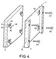
- FIG. 4 also shows an exploded view of the covering panel 5 and the front face 30 of the door 1.
- the fixing elements four in number, bear the reference 80. They are all identical. They comprise a square formed by a first wing 81 fixed to the covering panel 5 by at least one screw 82 and a second wing 83 which penetrates between the front face 30 and the rear face of the door 1 by an opening 84.
- Each fixing element 80 also includes a tongue 86 which extends the first wing 82 downwards.
- the opening 84 also receives the tongue 86.
- Screws 85 the head of which is located towards the rear face of the door, cooperate with the second wings 83 of the brackets. The ends of the screws opposite the heads overcome the second wings 83, to immobilize the panel 5 covering relative to the front face 30 of the door when the tabs 86 have been engaged in the openings 84.
- the present invention is not limited to the examples described.
- the fastening elements may in particular have other shapes.
Landscapes
- Washing And Drying Of Tableware (AREA)
- Securing Of Glass Panes Or The Like (AREA)
Applications Claiming Priority (3)
| Application Number | Priority Date | Filing Date | Title |
|---|---|---|---|
| FR9114099 | 1991-11-15 | ||
| FR9114099A FR2683849B1 (fr) | 1991-11-15 | 1991-11-15 | Appareil a porte munie d'un panneau d'habillage. |
| DE4312482A DE4312482A1 (de) | 1991-11-15 | 1993-04-16 | Gerät mit einer mit einer Verkleidungstafel versehenen Tür |
Publications (2)
| Publication Number | Publication Date |
|---|---|
| EP0543696A1 true EP0543696A1 (de) | 1993-05-26 |
| EP0543696B1 EP0543696B1 (de) | 1997-01-02 |
Family
ID=25924997
Family Applications (1)
| Application Number | Title | Priority Date | Filing Date |
|---|---|---|---|
| EP92402970A Expired - Lifetime EP0543696B1 (de) | 1991-11-15 | 1992-11-03 | Vorrichtung für eine Türe mit Deckplatte |
Country Status (4)
| Country | Link |
|---|---|
| EP (1) | EP0543696B1 (de) |
| DE (1) | DE4312482A1 (de) |
| ES (1) | ES2096057T3 (de) |
| FR (1) | FR2683849B1 (de) |
Cited By (9)
| Publication number | Priority date | Publication date | Assignee | Title |
|---|---|---|---|---|
| GB2298673A (en) * | 1995-03-09 | 1996-09-11 | Electrolux Zanussi Elettrodome | Domestic appliance with decorative front panel |
| EP0893090A1 (de) * | 1997-07-21 | 1999-01-27 | Wilfried Gronbach | Blende für einen Einrichtungsgegenstand, insbesondere für einen Blendenkasten für eine Geschirrspülmaschine |
| EP1127530A3 (de) * | 2000-01-27 | 2002-06-12 | AEG Hausgeräte GmbH | Haushaltsgerät mit einer frontseitigen Gerätetür |
| EP1529482A1 (de) * | 2003-11-07 | 2005-05-11 | Bonferraro S.p.A. | Eingebautes Haushaltsgerät mit an die Tür angebrachter dekorativer Vorsatzplatte |
| CN110072357A (zh) * | 2019-04-23 | 2019-07-30 | 无锡小天鹅电器有限公司 | 家用电器及其面板组件 |
| WO2020171394A1 (ko) * | 2019-02-18 | 2020-08-27 | 엘지전자 주식회사 | 식기세척기 |
| US20230384021A1 (en) * | 2019-04-15 | 2023-11-30 | Samsung Electronics Co., Ltd. | Refrigerator |
| US12259179B2 (en) | 2020-04-08 | 2025-03-25 | Samsung Electronics Co., Ltd. | Refrigerator |
| US12270595B2 (en) | 2019-08-20 | 2025-04-08 | Samsung Electronics Co., Ltd. | Refrigerator and home appliance |
Citations (5)
| Publication number | Priority date | Publication date | Assignee | Title |
|---|---|---|---|---|
| DE7305982U (de) * | 1973-02-16 | 1974-03-01 | Miele & Cie | Geschirrspülmaschine mit einer MontageÖffnung unterhalb der Fronttür |
| DE2365027A1 (de) * | 1973-12-28 | 1975-07-10 | Miele & Cie | Wasch- oder geschirrspuelmaschine mit einer auswechselbaren dekorplatte |
| GB1518941A (en) * | 1975-08-06 | 1978-07-26 | Kitson J W | Pinths for cabinets |
| EP0261083A2 (de) * | 1986-07-29 | 1988-03-23 | SMEG S.p.A. | Vorrichtung für die Verbindung und schnelle Befestigung einer Verkleidungsplatte mit einer Haushaltgerätetür |
| DE8908233U1 (de) * | 1989-07-06 | 1989-08-31 | Paul Henke GmbH & Co KG, 4972 Löhne | Möbelbeschlag |
-
1991
- 1991-11-15 FR FR9114099A patent/FR2683849B1/fr not_active Expired - Fee Related
-
1992
- 1992-11-03 ES ES92402970T patent/ES2096057T3/es not_active Expired - Lifetime
- 1992-11-03 EP EP92402970A patent/EP0543696B1/de not_active Expired - Lifetime
-
1993
- 1993-04-16 DE DE4312482A patent/DE4312482A1/de not_active Ceased
Patent Citations (5)
| Publication number | Priority date | Publication date | Assignee | Title |
|---|---|---|---|---|
| DE7305982U (de) * | 1973-02-16 | 1974-03-01 | Miele & Cie | Geschirrspülmaschine mit einer MontageÖffnung unterhalb der Fronttür |
| DE2365027A1 (de) * | 1973-12-28 | 1975-07-10 | Miele & Cie | Wasch- oder geschirrspuelmaschine mit einer auswechselbaren dekorplatte |
| GB1518941A (en) * | 1975-08-06 | 1978-07-26 | Kitson J W | Pinths for cabinets |
| EP0261083A2 (de) * | 1986-07-29 | 1988-03-23 | SMEG S.p.A. | Vorrichtung für die Verbindung und schnelle Befestigung einer Verkleidungsplatte mit einer Haushaltgerätetür |
| DE8908233U1 (de) * | 1989-07-06 | 1989-08-31 | Paul Henke GmbH & Co KG, 4972 Löhne | Möbelbeschlag |
Cited By (13)
| Publication number | Priority date | Publication date | Assignee | Title |
|---|---|---|---|---|
| GB2298673A (en) * | 1995-03-09 | 1996-09-11 | Electrolux Zanussi Elettrodome | Domestic appliance with decorative front panel |
| GB2298673B (en) * | 1995-03-09 | 1998-05-06 | Electrolux Zanussi Elettrodome | Domestic electrical appliance with decorative front panel |
| EP0893090A1 (de) * | 1997-07-21 | 1999-01-27 | Wilfried Gronbach | Blende für einen Einrichtungsgegenstand, insbesondere für einen Blendenkasten für eine Geschirrspülmaschine |
| EP1127530A3 (de) * | 2000-01-27 | 2002-06-12 | AEG Hausgeräte GmbH | Haushaltsgerät mit einer frontseitigen Gerätetür |
| EP1529482A1 (de) * | 2003-11-07 | 2005-05-11 | Bonferraro S.p.A. | Eingebautes Haushaltsgerät mit an die Tür angebrachter dekorativer Vorsatzplatte |
| WO2020171394A1 (ko) * | 2019-02-18 | 2020-08-27 | 엘지전자 주식회사 | 식기세척기 |
| US11950741B2 (en) | 2019-02-18 | 2024-04-09 | Lg Electronics Inc. | Dishwasher |
| US20230384021A1 (en) * | 2019-04-15 | 2023-11-30 | Samsung Electronics Co., Ltd. | Refrigerator |
| US12281836B2 (en) * | 2019-04-15 | 2025-04-22 | Samsung Electronics Co., Ltd. | Refrigerator |
| CN110072357A (zh) * | 2019-04-23 | 2019-07-30 | 无锡小天鹅电器有限公司 | 家用电器及其面板组件 |
| CN110072357B (zh) * | 2019-04-23 | 2022-08-09 | 无锡小天鹅电器有限公司 | 家用电器及其面板组件 |
| US12270595B2 (en) | 2019-08-20 | 2025-04-08 | Samsung Electronics Co., Ltd. | Refrigerator and home appliance |
| US12259179B2 (en) | 2020-04-08 | 2025-03-25 | Samsung Electronics Co., Ltd. | Refrigerator |
Also Published As
| Publication number | Publication date |
|---|---|
| FR2683849A1 (fr) | 1993-05-21 |
| DE4312482A1 (de) | 1994-10-20 |
| FR2683849B1 (fr) | 1994-02-18 |
| EP0543696B1 (de) | 1997-01-02 |
| ES2096057T3 (es) | 1997-03-01 |
Similar Documents
| Publication | Publication Date | Title |
|---|---|---|
| EP0543696B1 (de) | Vorrichtung für eine Türe mit Deckplatte | |
| WO2010037938A2 (fr) | Procede de pose de panneaux sandwich | |
| EP0085630A1 (de) | Trennwand bestehend aus auf einem Skelett befestigten Platten, sowie Platte für eine derartige Trennwand | |
| EP0764749A1 (de) | Haltevorrichtung für ein, gegenüber der vertikalen Fassade einer Vorhängewand eines Gebäudes oder ähnlichen Konstruktion, freitragendes Element | |
| EP1248934A2 (de) | Kältegerät | |
| EP0684672B1 (de) | Gehäuse, insbesondere für Niederspannungsgeräte | |
| FR2516965A1 (fr) | Element de facade d'immeuble | |
| BE1006367A6 (fr) | Un montage prefabrique d'un encadrement de porte en bois et un procede de fabrication d'un montage d'encadrement de porte. | |
| EP1302601A1 (de) | Vorrichtung für inneres Trennwandsystem mit Hohlprofildichtung | |
| FR2521629A1 (fr) | Renvoi d'angle pour chassis ouvrant de porte ou de fenetre | |
| EP0834639A1 (de) | Vorrichtung für die Montage einer Verglasung in einem Tragrahm für eine Tür, ein Fenster oder ähnliches | |
| EP0821113B1 (de) | Senkrechtes Trennwandsystem mit Verbindungsklammern | |
| FR2797901A1 (fr) | Procede et dispositif pour fixer des panneaux sur un support | |
| FR2682151A1 (fr) | Procede de pose d'une moulure sur un dormant d'ouverture debordant du plan de son cadre de pose, dormant d'ouverture et moulure pour sa mise en óoeuvre. | |
| EP3227168A1 (de) | Anordnung für ein kraftfahrzeug mit einer baugruppe mit einem anschlag zur stütze eines dachelements | |
| FR2753733A1 (fr) | Dispositif de montage et d'immobilisation d'un poteau de support creux pour cloison interieure d'un local | |
| FR2641809A1 (fr) | Dispositif d'assemblage pour ossature de cloisons | |
| EP0243227A1 (de) | Befestigungsvorrichtung für Wand- und Deckenverkleidungspaneele | |
| FR2766507A1 (fr) | Dispositif pour la fixation d'un capot decoratif exterieur, pour facade de mur rideau d'immeuble ou analogue | |
| FR2719736A1 (fr) | Dispositif de montage pour plastron à rapporter sur deux montants, notamment pour coffret ou autre armoire électrique, et plastron et coffret correspondants. | |
| FR2616822A1 (fr) | Dispositif de fixation d'un panneau sur des montants | |
| FR2681087A1 (fr) | Dispositif pour la fixation rapide d'un bardage sur un mur. | |
| FR3075245A1 (fr) | Agencement d'une porte a panneau, coupe-feu, avec inserts de fixation et de centrage | |
| FR2596635A1 (fr) | Cabine de douche a ossature bois | |
| FR2712005A1 (fr) | Procédé et dispositif de fixation d'un panneau résistant au feu sur un support. |
Legal Events
| Date | Code | Title | Description |
|---|---|---|---|
| PUAI | Public reference made under article 153(3) epc to a published international application that has entered the european phase |
Free format text: ORIGINAL CODE: 0009012 |
|
| AK | Designated contracting states |
Kind code of ref document: A1 Designated state(s): ES FR GB GR IT SE |
|
| 17P | Request for examination filed |
Effective date: 19931109 |
|
| 17Q | First examination report despatched |
Effective date: 19940831 |
|
| GRAG | Despatch of communication of intention to grant |
Free format text: ORIGINAL CODE: EPIDOS AGRA |
|
| GRAH | Despatch of communication of intention to grant a patent |
Free format text: ORIGINAL CODE: EPIDOS IGRA |
|
| GRAH | Despatch of communication of intention to grant a patent |
Free format text: ORIGINAL CODE: EPIDOS IGRA |
|
| GRAA | (expected) grant |
Free format text: ORIGINAL CODE: 0009210 |
|
| AK | Designated contracting states |
Kind code of ref document: B1 Designated state(s): ES FR GB GR IT SE |
|
| PG25 | Lapsed in a contracting state [announced via postgrant information from national office to epo] |
Ref country code: GR Free format text: LAPSE BECAUSE OF FAILURE TO SUBMIT A TRANSLATION OF THE DESCRIPTION OR TO PAY THE FEE WITHIN THE PRESCRIBED TIME-LIMIT Effective date: 19970102 |
|
| ITF | It: translation for a ep patent filed | ||
| GBT | Gb: translation of ep patent filed (gb section 77(6)(a)/1977) |
Effective date: 19970130 |
|
| REG | Reference to a national code |
Ref country code: ES Ref legal event code: FG2A Ref document number: 2096057 Country of ref document: ES Kind code of ref document: T3 |
|
| PLBE | No opposition filed within time limit |
Free format text: ORIGINAL CODE: 0009261 |
|
| STAA | Information on the status of an ep patent application or granted ep patent |
Free format text: STATUS: NO OPPOSITION FILED WITHIN TIME LIMIT |
|
| 26N | No opposition filed | ||
| PGFP | Annual fee paid to national office [announced via postgrant information from national office to epo] |
Ref country code: SE Payment date: 20001023 Year of fee payment: 9 Ref country code: GB Payment date: 20001023 Year of fee payment: 9 |
|
| PGFP | Annual fee paid to national office [announced via postgrant information from national office to epo] |
Ref country code: ES Payment date: 20001108 Year of fee payment: 9 |
|
| PGFP | Annual fee paid to national office [announced via postgrant information from national office to epo] |
Ref country code: FR Payment date: 20001121 Year of fee payment: 9 |
|
| PG25 | Lapsed in a contracting state [announced via postgrant information from national office to epo] |
Ref country code: GB Free format text: LAPSE BECAUSE OF NON-PAYMENT OF DUE FEES Effective date: 20011103 |
|
| PG25 | Lapsed in a contracting state [announced via postgrant information from national office to epo] |
Ref country code: SE Free format text: LAPSE BECAUSE OF NON-PAYMENT OF DUE FEES Effective date: 20011104 Ref country code: ES Free format text: LAPSE BECAUSE OF NON-PAYMENT OF DUE FEES Effective date: 20011104 |
|
| REG | Reference to a national code |
Ref country code: GB Ref legal event code: IF02 |
|
| GBPC | Gb: european patent ceased through non-payment of renewal fee |
Effective date: 20011103 |
|
| EUG | Se: european patent has lapsed |
Ref document number: 92402970.5 |
|
| PG25 | Lapsed in a contracting state [announced via postgrant information from national office to epo] |
Ref country code: FR Free format text: LAPSE BECAUSE OF NON-PAYMENT OF DUE FEES Effective date: 20020730 |
|
| REG | Reference to a national code |
Ref country code: FR Ref legal event code: ST |
|
| REG | Reference to a national code |
Ref country code: FR Ref legal event code: ST |
|
| REG | Reference to a national code |
Ref country code: ES Ref legal event code: FD2A Effective date: 20021213 |
|
| PG25 | Lapsed in a contracting state [announced via postgrant information from national office to epo] |
Ref country code: IT Free format text: LAPSE BECAUSE OF NON-PAYMENT OF DUE FEES Effective date: 20051103 |