EP0544295A1 - Dreiachsige Schubelement-Modulation - Google Patents
Dreiachsige Schubelement-Modulation Download PDFInfo
- Publication number
- EP0544295A1 EP0544295A1 EP92120209A EP92120209A EP0544295A1 EP 0544295 A1 EP0544295 A1 EP 0544295A1 EP 92120209 A EP92120209 A EP 92120209A EP 92120209 A EP92120209 A EP 92120209A EP 0544295 A1 EP0544295 A1 EP 0544295A1
- Authority
- EP
- European Patent Office
- Prior art keywords
- rate change
- thruster
- sample period
- thrusters
- residual
- Prior art date
- Legal status (The legal status is an assumption and is not a legal conclusion. Google has not performed a legal analysis and makes no representation as to the accuracy of the status listed.)
- Granted
Links
Images


Classifications
-
- B—PERFORMING OPERATIONS; TRANSPORTING
- B64—AIRCRAFT; AVIATION; COSMONAUTICS
- B64G—COSMONAUTICS; VEHICLES OR EQUIPMENT THEREFOR
- B64G1/00—Cosmonautic vehicles
- B64G1/22—Parts of, or equipment specially adapted for fitting in or to, cosmonautic vehicles
- B64G1/24—Guiding or controlling apparatus, e.g. for attitude control
- B64G1/26—Guiding or controlling apparatus, e.g. for attitude control using jets
-
- B—PERFORMING OPERATIONS; TRANSPORTING
- B64—AIRCRAFT; AVIATION; COSMONAUTICS
- B64G—COSMONAUTICS; VEHICLES OR EQUIPMENT THEREFOR
- B64G1/00—Cosmonautic vehicles
- B64G1/22—Parts of, or equipment specially adapted for fitting in or to, cosmonautic vehicles
- B64G1/24—Guiding or controlling apparatus, e.g. for attitude control
- B64G1/244—Spacecraft control systems
Definitions
- the present invention relates to a three axis thruster modulation logic for control of a spacecraft.
- Pointing control amplitude is controlled by adjusting the width of the deadband.
- Pulse frequency, and hence excitation of flexible spacecraft modes, is indirectly controlled by adjusting the hysteresis value and the time constant of the feedback path.
- These methods are well known to those practicing three axis spacecraft control. They are all based on analog logic to modulate a set of jets for control about a single axis. Digital implementation is alluded to, but constitutes a digitalized version of the analog logic rather than an inherently digital design.
- pseudo rate modulator Another disadvantage of the pseudo rate modulator is that its low amplitude response is very non-linear. At some level its output is zero, for low amplitudes it simply does not fire. This characteristic has not been a significant problem when using low level thrusters, such as thrusters with a minimum impulse of approximately 0.004 lb-sec., but becomes more of a problem when using 5 lb thrusters, with a minimum impulse of approximately 0.09 lb-sec.
- the approach of this invention produces a proportional thrust impulse at any non zero level of input although it does introduce some lag time as the level becomes very low.
- the disadvantage associated with the lag can be overcome with a fractional modulation scheme, described later.
- Bittner improves on the pseudo rate modulator in a number of ways. Bittner eliminates the filtering in the feedback path around the non-linearity by feeding the derived rate information directly back to the state estimator where it alters the estimates of rate and position. Bittner also describes additional complexity in which the deadband and hysteresis are adjusted adaptively, based on observed pointing error, amplitude of low frequency oscillations and/or derived disturbance torque levels. This complexity can be used to adjust frequency of pulsing and thereby avoid excitation of certain spacecraft structural resonances. Bittner's improvements are still confined to a single axis and are based on analog logic although Bittner discusses how to digitally mimic this logic.
- Garg in U.S. Patent No. 4,848,706, extends use of the same type of modulator to a spacecraft where the torques produced by thrusters are not restricted to be orthogonal but the thrusters must still be arranged in groups with some thrusters of a group producing a torque opposite of that produced by the other thrusters in the group. He divides the thrusters into three groups with torque vectors not necessarily being orthogonal, then maps the control torque commands into components along the three thruster torque axes and finally applies the same pulse width/pulse frequency modulator to each thruster group. With this approach, Garg is able to achieve a minimum set of twelve thrusters per spacecraft as compared to a minimum of ten thrusters achieved by the present invention.
- the present invention provides a new method for pulse modulation of thrusters.
- the pulse modulation logic accepts three axis of input torque commands (or angular acceleration commands), and generates thruster selection and thruster timing information which can be used to fire thrusters for the purpose of attitude control and velocity change maneuvers.
- the three input angular acceleration commands are typically generated by onboard attitude information and control algorithms.
- the pulse modulation logic of the present invention is novel in that it works in all three axes simultaneously and is suitable for use with an arbitrary thruster configuration, including a configuration in which individual thrusters or thruster pairs do not produce torques about mutually orthogonal axes.
- the method is also designed to make the thrusters' torquing response to an input command as linear as possible, consistent with thrust level and thruster minimum impulse capability. This latter characteristic is an important feature which facilitates stabilization of a flexible spacecraft when using thrusters with large minimum impulse bits.
- the approach of the present invention is inherently digital, works on three axes simultaneously and is applicable to any fully controllable three axes thruster configuration. It is superior to the approach of Garg in that it achieves equivalent results when thrusters are arranged in pairs, but is also applicable to a spacecraft layout where no restrictions are laid on thruster placement except that the thrusters provide full three axis torquing capability. By maintaining near linearity even at very low levels, this approach allows application of the tools of linear analysis to achieve pointing and structural stability rather than indirect tuning of deadbands and hysteresis levels to adjust pulse frequency and thereby avoid excitation of spacecraft structural resonances.
- FIGS. 1A and 1B are schematic drawings showing a spacecraft controller with an emphasis on the three axis modulation logic of the present invention with FIG. 1A illustrating the right half of the schematic and FIG. 1B illustrating the left half of the schematic.
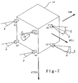
- FIG. 2 illustrates a possible thruster configuration for a spacecraft.
- the three axis thruster modulation logic of the present invention is illustrated in FIG. 1A within the block 8.
- the modulation logic accepts as input, three angular acceleration commands, one for each axis of control, ⁇ l c k, ⁇ 2 c k and ⁇ 3 c k where the numerals 1, 2 and 3 designate the axis, the superscript c designates "command" and the subscript k designates a particular sample period.
- the acceleration commands are produced by three controllers 50, 52 and 54 shown in FIG. 1B and discussed further below.
- the purpose of the modulation logic is to select appropriate thrusters and compute thruster on-time commands which will produce the angular accelerations as commanded.
- the logic is designed for digital implementation and thus assumes all operations occur repetitively at some sample period of T duration.
- the modulation logic in the boxes 10, 20 and 30 labeled "Accumulate Impulse", multiplies each angular acceleration command by the sample period duration T to convert acceleration into an equivalent rate change for the upcoming sample period. To the rate change, the logic adds any residual unfired rate change ⁇ 1 c k-1 , ⁇ 2 c k-1 and ⁇ 3 c k-1 from the prior sample time period k-1.
- the result represents the rate change commands ⁇ 1 c k , ⁇ 2 c k and ⁇ 3 c k which should be executed in the next sample period k.
- These rate change commands for all three axes, ⁇ ⁇ c k are input to the Thruster Select and Timing Logic (TSTL) 40, whose function it is to: 1) determine which thrusters to select to achieve the rate change commanded; and 2) compute the on-time durations for each of the selected thrusters.
- TSTL Thruster Select and Timing Logic
- the TSTL function is, for a general thruster configuration, a difficult task. It requires knowledge of spacecraft mass properties, thruster placement and alignment relative to spacecraft center of mass, and thruster physical constraints such as minimum on-time and impulse versus on-time characteristics. For typical thruster configurations, there is usually more than one thruster combination possible which will provide a given control torque. Thus, some sort of decision process is required.
- an algorithm based on linear programming is employed to optimally select thrusters which minimize the total thruster on-time, and hence, total fuel consumption.
- the TSTL algorithm while utilizing information about spacecraft mass properties, thruster placement and thruster alignment relative to spacecraft center of mass, assumes an ideal proportional relationship between force impulse and on-time.
- the resulting ideal computed on-times are adjusted to compensate for thruster losses at the start of each pulse, then further adjusted to avoid commanding thruster on-times longer than the control logic sample period or shorter than some minimum corresponding to the minimum repeatable impulse capability of the thrusters.
- Non-optimal table driven algorithms are also possible.
- the TSTL function includes the following capabilities: 1) it uses spacecraft mass properties together with thruster placement and alignment information to select thrusters and compute necessary on-time commands; 2) on-times smaller than some minimum determined by thruster performance characteristics are truncated or rounded to either zero or the minimum allowable; 3) on-times greater than the sample period are truncated to less than or equal to the sample period; 4) to perform velocity change maneuvers, the TSTL must have the ability to command certain thrusters, designated by ground control, to a full on-state with off pulsing for attitude control; and 5) it must include logic to choose between redundant thrusters which are capable of performing equivalent torquing.
- One of the functions performed by the TSTL is to decide if a computed on-time is large enough to be fired. If it is too small, the TSTL must choose not to fire. This is analogous to the deadband incorporated in the "Pseudo-Rate Modulator". There is, however, nothing in the present invention similar to the hysteresis in the "Pseudo-Rate Modulator".
- the modulation logic uses this information to compute a best estimate of the actual rate change that corresponds to the selected thrusters and respective on-times. This calculation is shown at block 42.
- the actual rate change estimate would be identical to the commanded rate change. In practice however, it may differ for a number of reasons. As already mentioned, if the commanded rate change produces an on-time below the minimum allowable for a given thruster, then that thruster will not be fired at all. On the other hand, if a thruster on-time greater than the sample period is necessary, then the thruster can be fired at most for the entire sample period. A longer firing is of course possible, but not in the current sample period. Approximations in the TSTL algorithm are still another source of potential differences between the commanded rate change and the actual rate change estimate.
- the actual rate change estimate ⁇ ⁇ a k is subtracted from the commanded rate change ⁇ ⁇ c k at 44 to obtain a residual, or unfired rate change ⁇ ⁇ k .
- This residual is held over for a sample period, passed through a limiter 12, 22 or 32 and added back in at the next opportunity.
- the function of the limiters is to preclude "wind up” which might otherwise occur when a large acceleration command is input.
- the logic achieves a saturation effect with no "wind up". No matter how big or how long a saturating acceleration command is input, the logic will always come out of saturation within one sample period after the acceleration command drops below a saturated level.
- the thruster selection and thruster on-times from the TSTL are directed to the thruster output Hardware Processing 46 which then commands the thrusters 48 to fire.
- the firing of the thrusters will, of course, affect the spacecraft dynamics and attitude which will be detected by the Inertial Reference Unit and Earth Sensor as shown in FIGS. 1A and 1B.
- the three axis thruster modulation incorporates features that allow it to closely approximate a proportional control.
- One such feature is the feed back path which injects the residual unfired rate change into the command.
- the residual represents that portion of a rate change command that was not executed in the prior sample period. This feature precludes loss of an command too small to be fired on a given sample period, by adding it to the next fire command. If the resulting sum is large enough to be fired, it will be fired. For example, suppose an input acceleration command was constant at a level such that the thruster impulse required to implement it is half a minimum impulse bit every sample period.
- Another feature which enhances proportional control is the three axis nature of the system.
- the improvement obtained is dependent upon thruster configuration.
- thrusters E1 and E2 are used for yaw control and thrusters A1, A2, A3 and A4 are used for roll and pitch.
- Additional thrusters not shown, can be added to provide redundant control.
- Simulation has shown that angular acceleration commands from orthogonal axes often result in impulse commands to the same thruster.
- a thruster such as A1 mounted on the extreme corner of the spacecraft produces both a roll and a pitch torque.
- both roll and pitch controllers command an angular acceleration resulting in half an impulse bit of thrust from this thruster, the two halves will combine to produce a full impulse bit which is then fired.
- single axis controllers were used, one axis alone would have to develop sufficient pointing error to command a full impulse.
- this behavior reduces the minimum impulse bit that can be fired in roll and pitch by half, thus enhancing the modulator's ability to approximate proportionally.
- FIG. 1B illustrates one method in which the three axis modulation logic of the invention can be incorporated into an overall control system. Other methods are also possible.
- three similar controllers 50, 52, 54 are used to generate the angular acceleration commands to the three axis modulation logic.
- Each controller is comprised of a state estimator which estimates position, rate and acceleration bias in each axis; control gains 56 which combine the estimates; and notch filters 58, 60 and 62 that can be used to create a phase or gain notch to stabilize flexible spacecraft dynamics.
- Inputs to the estimators include gyro measurements of rate in all axes, earth sensor measurements of roll and pitch and a feedforward of the actual rate change command ⁇ ⁇ a created by firing the thrusters.
- Some embodiments may not include gyro inputs for all axes, or may employ some attitude sensor other than an earth sensor, for example, a beacon sensor.
- Feedforward of the actual rate change is also not essential, but is desirable as it allows lower bandwidth filtering in the state estimators.
- the state estimators are limited to third order functions and estimate only rigid body rates. Any notch filtering to compensate for flexible dynamics is performed in a subsequent stage. Other embodiments might combine these functions into a single higher order estimator which estimates flexible mode states as well as rigid body states.
- the three axis modulation logic of the invention can be used in any of these various embodiments of a three axis control system.
- a major problem in fixed-modulation period control of conventional thrusters is the non-linearity in response for duty cycles near (but not at) zero or 100%. This is due to the finite time required for the valves to operate, and is typically characterized by a minimum on-time and minimum off-time.
- the achievable fixed-modulation duty cycles fall into three categories: 1) Zero percent, 2) Duty cycles in the range from (minimum on-time)/(modulation period) to (minimum off-time) / (modulation period), and 3) 100%.
- the control algorithm commands a duty cycle slightly above zero percent (very short on-pulses) or slightly below 100% (very short off-pulses), this cannot be achieved in a single modulation period with thrusters that are nominally continuously on or off.
- Two solutions are provided to mitigate this nonlinearity: error accumulation and fractional modulation.
- Error accumulation mitigates the nonlinearity by achieving the desired effective duty cycle across multiple modulation periods.
- the error between commanded and actual rate change is accumulated until it exceeds the minimum on-time or off-time, as applicable.
- a potential drawback of this technique is that it excites the spacecraft at subharmonics of the modulation frequency which can result in unacceptably large attitude oscillations when these subharmonics correspond to spacecraft resonance modes.
- Fractional modulation mitigates the nonlinearity by using the attitude control thrusters at nominal duty cycles that are well within the second duty cycle range: significantly above zero percent, yet significantly below 100%.
- the nominal duty cycle is chosen so that, as the control algorithm requests changes from the nominal duty cycle for attitude control, the requested off-nominal duty cycles will still lie in the achievable duty cycle range, unconstrained by the minimum on-time or off-time.
- Fractional modulation avoids commanding thruster duty cycles in duty cycle ranges near zero or 100 percent duty cycle.
- a simple comparison of fractional and conventional modulation is a south maneuver using four thrusters mounted at the corners of the north face of a cube, each producing a force normal to the north face, directly south.
- a typical conventional south maneuver modulation nominally operates one diagonal pair of thrusters continuously on (100% duty cycle), and off-pulses one or the other for attitude control.
- the other diagonal pair is normally off (zero duty cycle), and one or the other is on-pulsed for attitude control.
- a typical fractional modulation south maneuver might nominally operate one diagonal pair of thrusters at a nominal duty cycle of 75%, and the other diagonal pair of thrusters at a nominal duty cycle of 25%.
- the force of all four thrusters can be smoothly increased (e.g., by going from 25 to 26%, or from 75 to 76%) or smoothly decreased. This gives the thruster control a much smoother response, and avoids the subharmonic modulation concerns as well.
- the fractional modulation scheme supplements the error accumulation scheme rather than being a substitute.
- the drawback of the fractional modulation scheme is that fuel efficiency is typically less since the thrusters are usually most efficient at near 100% modulation. Since it only needs to be used when small control authority is required and the resulting subharmonics of the error accumulation scheme are undesirable, the fractional modulation scheme can be reserved for times when the finer control is worth the fuel penalty.
- the fractional modulation scheme can also be used for cases where, nominally, no thrusters would be on, e.g., two opposing attitude thrusters. Clearly here there is a significant fuel penalty for running both thrusters at 10% duty cycle. However, there are cases, such as when transitioning from a thruster mode to a very low authority control mode, like magnetic torque control where the fuel penalty is minimal (short time period) and the benefit is significant.
- the modulation logic of the present invention has several advantages over the prior art. It is an advantage that the modulation logic is applicable to spacecraft with an arbitrary thruster configuration, including a configuration in which individual thrusters or thruster pairs do not produce torques about control axes or even about mutually orthogonal axes. It is another advantage that since the modulation logic works in three axes simultaneously, it offers the potential for fuel optimization by taking advantage of thruster geometry to create torques about multiple control axes with a single thruster pulse. It is to be understood that the invention is not limited to the exact construction or method illustrated and described above, but that various changes and modifications may be made without departing from the spirit and scope of the invention as defined in the following claims.
Landscapes
- Engineering & Computer Science (AREA)
- Remote Sensing (AREA)
- Chemical & Material Sciences (AREA)
- Combustion & Propulsion (AREA)
- Radar, Positioning & Navigation (AREA)
- Aviation & Aerospace Engineering (AREA)
- Automation & Control Theory (AREA)
- Control Of Position, Course, Altitude, Or Attitude Of Moving Bodies (AREA)
Applications Claiming Priority (2)
| Application Number | Priority Date | Filing Date | Title |
|---|---|---|---|
| US80065891A | 1991-11-27 | 1991-11-27 | |
| US800658 | 1996-12-31 |
Publications (2)
| Publication Number | Publication Date |
|---|---|
| EP0544295A1 true EP0544295A1 (de) | 1993-06-02 |
| EP0544295B1 EP0544295B1 (de) | 1997-12-29 |
Family
ID=25178994
Family Applications (1)
| Application Number | Title | Priority Date | Filing Date |
|---|---|---|---|
| EP92120209A Expired - Lifetime EP0544295B1 (de) | 1991-11-27 | 1992-11-26 | Dreiachsige Schubelement-Modulation |
Country Status (4)
| Country | Link |
|---|---|
| US (1) | US5310143A (de) |
| EP (1) | EP0544295B1 (de) |
| CA (1) | CA2076894C (de) |
| DE (1) | DE69223749T2 (de) |
Cited By (4)
| Publication number | Priority date | Publication date | Assignee | Title |
|---|---|---|---|---|
| US5456429A (en) * | 1993-08-02 | 1995-10-10 | Loral Corp. | Thrust maneuver system |
| EP0750239A3 (de) * | 1995-06-02 | 1997-06-04 | Daimler Benz Aerospace Ag | Vorrichtung zur Lage- und gegebenenfalls Positionsregelung eines Raumfahrzeuges sowie zugehöriges Verfahren |
| CN103010486A (zh) * | 2012-12-11 | 2013-04-03 | 北京控制工程研究所 | 一种多分支、多路推力器交叉组合喷气分配方法 |
| EP3088981A4 (de) * | 2014-05-27 | 2017-09-13 | Beijing Aerospace Wanda Hi-Tech Ltd. | Nichtorthogonale six-rod-satellitenkommunikation in einem bewegungsservosystem und steuerverfahren |
Families Citing this family (13)
| Publication number | Priority date | Publication date | Assignee | Title |
|---|---|---|---|---|
| DE4129627C2 (de) * | 1991-09-06 | 1994-08-04 | Deutsche Aerospace | Vorrichtung und Verfahren zur Lageregelung eines um eine körperfeste Achse in Rotation zu versetzenden Raumfahrzeuges |
| US5400252A (en) * | 1992-12-22 | 1995-03-21 | Space Systems/Loral, Inc. | Spacecraft East/West orbit control during a North or South stationkeeping maneuver |
| US5395076A (en) * | 1993-03-19 | 1995-03-07 | Martin Marietta Corporation | Spacecraft velocity change maneuvers by variable arcjets |
| US5610820A (en) * | 1995-03-23 | 1997-03-11 | Martin Marietta Corp. | Minimum propellant, zero momentum spacecraft attitude control system |
| US5646847A (en) * | 1995-08-25 | 1997-07-08 | Martin Marietta Corp. | Universal thruster selection logic for spacecraft attitude control |
| KR970055208A (ko) * | 1995-12-28 | 1997-07-31 | 김광호 | 서보모터의 속도제어방법 및 속도제어장치 |
| US6052630A (en) * | 1996-12-17 | 2000-04-18 | Space Systems/Loral, Inc. | Thruster optimized pair selection |
| US6260805B1 (en) * | 1998-12-29 | 2001-07-17 | Hughes Electronics Corporation | Method of controlling attitude of a momentum biased spacecraft during long-duration thruster firings |
| US6267326B1 (en) | 1999-08-09 | 2001-07-31 | The Boeing Company | Universal driver circuit for actuating both valves and ordnances |
| GB0203950D0 (en) * | 2002-02-20 | 2002-04-03 | Astrium Ltd | Method and system for balancing thrust demands |
| DE10236570B4 (de) * | 2002-08-08 | 2013-05-29 | Astrium Gmbh | Verfahren zur treibstoffoptimalen Ansteuerung einer Düsenanordnung |
| US7918420B2 (en) * | 2007-07-17 | 2011-04-05 | The Boeing Company | System and methods for simultaneous momentum dumping and orbit control |
| US10006445B2 (en) | 2014-02-18 | 2018-06-26 | The George Washington University | Method and system for a programmable and fault tolerant pulsed plasma thruster |
Citations (4)
| Publication number | Priority date | Publication date | Assignee | Title |
|---|---|---|---|---|
| US3944172A (en) * | 1972-04-14 | 1976-03-16 | Erno Raumfahrttechnik Gmbh | Attitude control for space vehicle |
| US4567564A (en) * | 1980-08-19 | 1986-01-28 | Messerschmitt-Bolkow-Blohm Gesellschaft Mit Beschrankter Haftung | Arrangement for the attitude stabilization of flexible vehicles with weakly-dampened structural vibrations and discontinuous control intervention |
| US4848706A (en) * | 1988-02-29 | 1989-07-18 | Ford Aerospace Corporation | Spacecraft attitude control using coupled thrusters |
| EP0371344A2 (de) * | 1988-11-18 | 1990-06-06 | Hughes Aircraft Company | Stabilisierung eines drallstabilisierten Raumfahrzeuges mit beliebiger Form |
Family Cites Families (3)
| Publication number | Priority date | Publication date | Assignee | Title |
|---|---|---|---|---|
| US4599697A (en) * | 1982-08-11 | 1986-07-08 | Ford Aerospace & Communications Corporation | Digital PWPF three axis spacecraft attitude control |
| US4725024A (en) * | 1985-11-15 | 1988-02-16 | Ford Aerospace & Communications Corporation | Method for spinning up a three-axis controlled spacecraft |
| US5130931A (en) * | 1990-07-13 | 1992-07-14 | General Electric Company | Spacecraft attitude and velocity control system |
-
1992
- 1992-08-26 CA CA002076894A patent/CA2076894C/en not_active Expired - Fee Related
- 1992-11-26 EP EP92120209A patent/EP0544295B1/de not_active Expired - Lifetime
- 1992-11-26 DE DE69223749T patent/DE69223749T2/de not_active Expired - Fee Related
-
1993
- 1993-06-10 US US08/075,843 patent/US5310143A/en not_active Expired - Lifetime
Patent Citations (4)
| Publication number | Priority date | Publication date | Assignee | Title |
|---|---|---|---|---|
| US3944172A (en) * | 1972-04-14 | 1976-03-16 | Erno Raumfahrttechnik Gmbh | Attitude control for space vehicle |
| US4567564A (en) * | 1980-08-19 | 1986-01-28 | Messerschmitt-Bolkow-Blohm Gesellschaft Mit Beschrankter Haftung | Arrangement for the attitude stabilization of flexible vehicles with weakly-dampened structural vibrations and discontinuous control intervention |
| US4848706A (en) * | 1988-02-29 | 1989-07-18 | Ford Aerospace Corporation | Spacecraft attitude control using coupled thrusters |
| EP0371344A2 (de) * | 1988-11-18 | 1990-06-06 | Hughes Aircraft Company | Stabilisierung eines drallstabilisierten Raumfahrzeuges mit beliebiger Form |
Cited By (5)
| Publication number | Priority date | Publication date | Assignee | Title |
|---|---|---|---|---|
| US5456429A (en) * | 1993-08-02 | 1995-10-10 | Loral Corp. | Thrust maneuver system |
| EP0750239A3 (de) * | 1995-06-02 | 1997-06-04 | Daimler Benz Aerospace Ag | Vorrichtung zur Lage- und gegebenenfalls Positionsregelung eines Raumfahrzeuges sowie zugehöriges Verfahren |
| CN103010486A (zh) * | 2012-12-11 | 2013-04-03 | 北京控制工程研究所 | 一种多分支、多路推力器交叉组合喷气分配方法 |
| CN103010486B (zh) * | 2012-12-11 | 2015-04-22 | 北京控制工程研究所 | 一种多分支、多路推力器交叉组合喷气分配方法 |
| EP3088981A4 (de) * | 2014-05-27 | 2017-09-13 | Beijing Aerospace Wanda Hi-Tech Ltd. | Nichtorthogonale six-rod-satellitenkommunikation in einem bewegungsservosystem und steuerverfahren |
Also Published As
| Publication number | Publication date |
|---|---|
| EP0544295B1 (de) | 1997-12-29 |
| DE69223749D1 (de) | 1998-02-05 |
| CA2076894A1 (en) | 1993-05-28 |
| US5310143A (en) | 1994-05-10 |
| CA2076894C (en) | 1998-11-03 |
| DE69223749T2 (de) | 1998-04-23 |
Similar Documents
| Publication | Publication Date | Title |
|---|---|---|
| EP0544295B1 (de) | Dreiachsige Schubelement-Modulation | |
| Liu et al. | An anti-disturbance PD control scheme for attitude control and stabilization of flexible spacecrafts | |
| CA1285256C (en) | Method for spinning up a three-axis controlled spacecraft | |
| US4567564A (en) | Arrangement for the attitude stabilization of flexible vehicles with weakly-dampened structural vibrations and discontinuous control intervention | |
| US5610820A (en) | Minimum propellant, zero momentum spacecraft attitude control system | |
| US6292722B1 (en) | Magnetic torquer control with thruster augmentation | |
| DE69300535T2 (de) | Lageregelung und Momentenausgleich für Raumfahrzeuge mittels kardanisch befestigten und kontinuierlich gedrosselten Triebwerken. | |
| US4599697A (en) | Digital PWPF three axis spacecraft attitude control | |
| CA2062308C (en) | Compensated transition for spacecraft attitude control | |
| EP0453096A1 (de) | Vorrichtung zur Steuerung der Lage eines Satelliten in einer geneigten Umlaufbahn | |
| US5610848A (en) | Robust resonance reduction using staggered posicast filters | |
| EP0544297A1 (de) | Verfahren zur Steuerung der Abstandseinhaltung eines flexiblen Raumfahrzeuges mittels bordseitigem Verstärkungsfaktor-Einteilungsplan | |
| EP0251692B1 (de) | Umlaufbahnsteuersystem eines Satelliten | |
| US6340138B1 (en) | Stationkeeping method utilizing open-loop thruster pulses and closed-loop authority limited momentum storage devices | |
| US5984237A (en) | Delta-V targeting system for three-axis controlled spacecraft | |
| US6921049B2 (en) | System for counteracting a disturbance in a spacecraft | |
| Doman et al. | Control allocation of reaction control jets and aerodynamic surfaces for entry vehicles | |
| Ieko et al. | New design method for pulse-width modulation control systems via digital redesign | |
| US8401717B2 (en) | Actuator control reducing the level of vibration of an associated flexible structure | |
| Jalali-Naini et al. | Preliminary Design of Spacecraft Attitude Control with Pulse-Width Pulse-Frequency Modulator for Rest-to-Rest Maneuvers | |
| EP1086409B1 (de) | Kraft- und geschwindigkeitsbegrenzte steuerung | |
| Vaeth | Compatibility of impulse modulation techniques with attitude sensor noise and spacecraft maneuvering | |
| Ikeda et al. | Large-angle Attitude Maneuver of Spacecraft by Reaction Control System | |
| Bang et al. | Feedback control for slew maneuver using on-off thrusters | |
| US20040122568A1 (en) | System for controlling the attitude of a geostationary satellite |
Legal Events
| Date | Code | Title | Description |
|---|---|---|---|
| PUAI | Public reference made under article 153(3) epc to a published international application that has entered the european phase |
Free format text: ORIGINAL CODE: 0009012 |
|
| AK | Designated contracting states |
Kind code of ref document: A1 Designated state(s): DE FR GB IT |
|
| 17P | Request for examination filed |
Effective date: 19931130 |
|
| 17Q | First examination report despatched |
Effective date: 19960321 |
|
| GRAG | Despatch of communication of intention to grant |
Free format text: ORIGINAL CODE: EPIDOS AGRA |
|
| GRAG | Despatch of communication of intention to grant |
Free format text: ORIGINAL CODE: EPIDOS AGRA |
|
| GRAH | Despatch of communication of intention to grant a patent |
Free format text: ORIGINAL CODE: EPIDOS IGRA |
|
| GRAH | Despatch of communication of intention to grant a patent |
Free format text: ORIGINAL CODE: EPIDOS IGRA |
|
| GRAA | (expected) grant |
Free format text: ORIGINAL CODE: 0009210 |
|
| AK | Designated contracting states |
Kind code of ref document: B1 Designated state(s): DE FR GB IT |
|
| REF | Corresponds to: |
Ref document number: 69223749 Country of ref document: DE Date of ref document: 19980205 |
|
| ITF | It: translation for a ep patent filed | ||
| ET | Fr: translation filed | ||
| REG | Reference to a national code |
Ref country code: GB Ref legal event code: 732E |
|
| PLBE | No opposition filed within time limit |
Free format text: ORIGINAL CODE: 0009261 |
|
| STAA | Information on the status of an ep patent application or granted ep patent |
Free format text: STATUS: NO OPPOSITION FILED WITHIN TIME LIMIT |
|
| 26N | No opposition filed | ||
| REG | Reference to a national code |
Ref country code: FR Ref legal event code: TP Ref country code: FR Ref legal event code: CA Ref country code: FR Ref legal event code: CD |
|
| REG | Reference to a national code |
Ref country code: GB Ref legal event code: IF02 |
|
| PGFP | Annual fee paid to national office [announced via postgrant information from national office to epo] |
Ref country code: FR Payment date: 20031119 Year of fee payment: 12 |
|
| PG25 | Lapsed in a contracting state [announced via postgrant information from national office to epo] |
Ref country code: FR Free format text: LAPSE BECAUSE OF NON-PAYMENT OF DUE FEES Effective date: 20050729 |
|
| REG | Reference to a national code |
Ref country code: FR Ref legal event code: ST |
|
| PGFP | Annual fee paid to national office [announced via postgrant information from national office to epo] |
Ref country code: IT Payment date: 20081127 Year of fee payment: 17 |
|
| PGFP | Annual fee paid to national office [announced via postgrant information from national office to epo] |
Ref country code: DE Payment date: 20081223 Year of fee payment: 17 |
|
| PGFP | Annual fee paid to national office [announced via postgrant information from national office to epo] |
Ref country code: GB Payment date: 20081128 Year of fee payment: 17 |
|
| GBPC | Gb: european patent ceased through non-payment of renewal fee |
Effective date: 20091126 |
|
| PG25 | Lapsed in a contracting state [announced via postgrant information from national office to epo] |
Ref country code: DE Free format text: LAPSE BECAUSE OF NON-PAYMENT OF DUE FEES Effective date: 20100601 |
|
| PG25 | Lapsed in a contracting state [announced via postgrant information from national office to epo] |
Ref country code: GB Free format text: LAPSE BECAUSE OF NON-PAYMENT OF DUE FEES Effective date: 20091126 |
|
| PG25 | Lapsed in a contracting state [announced via postgrant information from national office to epo] |
Ref country code: IT Free format text: LAPSE BECAUSE OF NON-PAYMENT OF DUE FEES Effective date: 20091126 |