EP0544521B1 - Terminal pour la connexion de fils - Google Patents
Terminal pour la connexion de fils Download PDFInfo
- Publication number
- EP0544521B1 EP0544521B1 EP92310790A EP92310790A EP0544521B1 EP 0544521 B1 EP0544521 B1 EP 0544521B1 EP 92310790 A EP92310790 A EP 92310790A EP 92310790 A EP92310790 A EP 92310790A EP 0544521 B1 EP0544521 B1 EP 0544521B1
- Authority
- EP
- European Patent Office
- Prior art keywords
- terminal
- tab
- core
- core wire
- wires
- Prior art date
- Legal status (The legal status is an assumption and is not a legal conclusion. Google has not performed a legal analysis and makes no representation as to the accuracy of the status listed.)
- Expired - Lifetime
Links
Images


Classifications
-
- H—ELECTRICITY
- H01—ELECTRIC ELEMENTS
- H01R—ELECTRICALLY-CONDUCTIVE CONNECTIONS; STRUCTURAL ASSOCIATIONS OF A PLURALITY OF MUTUALLY-INSULATED ELECTRICAL CONNECTING ELEMENTS; COUPLING DEVICES; CURRENT COLLECTORS
- H01R4/00—Electrically-conductive connections between two or more conductive members in direct contact, i.e. touching one another; Means for effecting or maintaining such contact; Electrically-conductive connections having two or more spaced connecting locations for conductors and using contact members penetrating insulation
- H01R4/10—Electrically-conductive connections between two or more conductive members in direct contact, i.e. touching one another; Means for effecting or maintaining such contact; Electrically-conductive connections having two or more spaced connecting locations for conductors and using contact members penetrating insulation effected solely by twisting, wrapping, bending, crimping, or other permanent deformation
- H01R4/18—Electrically-conductive connections between two or more conductive members in direct contact, i.e. touching one another; Means for effecting or maintaining such contact; Electrically-conductive connections having two or more spaced connecting locations for conductors and using contact members penetrating insulation effected solely by twisting, wrapping, bending, crimping, or other permanent deformation by crimping
- H01R4/188—Electrically-conductive connections between two or more conductive members in direct contact, i.e. touching one another; Means for effecting or maintaining such contact; Electrically-conductive connections having two or more spaced connecting locations for conductors and using contact members penetrating insulation effected solely by twisting, wrapping, bending, crimping, or other permanent deformation by crimping having an uneven wire-receiving surface to improve the contact
Definitions
- the present invention relates to a connector terminal and an inter-connecting terminal and more particularly to a terminal provided a core wire-fixing barrel in which two or more electric wires are inserted and pressured on the wires to contact with the wires and fix them, and for reducing the contact resistance between electric wires in fixing two or more electric wires thereto by a barrel and between the wires and the terminal.
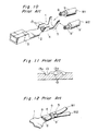
- a connector terminal to be used to connect electric wires of a wire harness of an automobile or an electric office automation equipments has a construction as shown in Fig. 10.
- An inter-connector terminal or an intermediate joint terminal for connecting electric wires without the intermediary of a connector has a construction as shown in Fig. 13.
- the connector terminal 1 which is solid comprises an electrical contact portion 3 disposed in the front of a bottom 2 and a core wire-fixing barrel 4 and a coating film-fixing barrel 5 both disposed in the rear of the bottom 2.
- the inter-connecting terminal 6 U-shaped in its sectional configuration consists of only a core wire-fixing barrel 7.
- W-type fixing method C-type fixing method or F-type fixing method, soldering or welding is used to connect the electric wires to the connector terminal 1 or the interconnecting terminal 6.
- F-type fixing method is most widely used because this method is most efficient of these methods.
- the inter-connecting terminal 6 is placed on an anvil 11 of a presser 10.
- the core wire 8 of the electric wire W1 and the core wire 8' of electric wire W2 are inserted into the core wire-fixing barrel 4 with the core wire 8 held in a higher space and the core wire 8' held in a lower space.
- a crimper 12 is moved downward to deform the barrel 7 and fix the core wires 8 and 8' to the interconnecting terminal 6.
- the core wire 8 of the electric wire W1 and the core wire 8' of the electric wire W2 are inserted into the core wire-fixing barrel 4 and the coating film 9 of the electric wire W1 and the coating film 9' of the electric wire W2 are inserted into the coating film-fixing barrel 5. Then, the crimper 12 is moved downward to deform the barrels 4 and 5 and fix the core wires 8 and 8' to the core wire-fixing barrel 4 and coating films 9 and 9' to the coating film-fixing barrel 5.
- the conventional connector terminal 1 or the inter-connecting terminal 6 has a problem that oxide film formed on the surface of the core wires 8 and 8' acts as a contact resistance in connecting the core wires 8 and 8' with the connector terminal 1 or the inter-connecting terminal 6.
- a plurality of serrations 13 is formed on the inner surface of the bottom of the core wire-fixing barrels 4 and 7 and that of the side walls thereof so as to shear and remove the oxide film from the core wires 8 and 8' by means of edges 13a of the serrations 13.
- the core wire 8' disposed in the lower space of each of the barrels 4 and 7 contacts the serrations 13 formed on the bottom thereof in a large area, but the core wire 8 mainly contacts the serrations 13 formed on upper portions of the side walls of the barrels 4 and 7. Therefore, the core wire 8 contacts the serrations 13 in a small area.
- the core wires 8 and 8' disposed along the boundary (X) between the electric wires W1 and W2 do not contact the serrations 13. Accordingly, the oxide film is not removed therefrom along the boundary (X). That is, there is a possibility that the core wires 8 and 8' are not connected electrically.
- the electric wires W1 and W2 are not electrically connected with each other because of the above-described reason.
- a terminal including a core wire-fixing barrel which is approximately U-shaped so as to have side walls and is crimped on two or more core wires inserted thereinto, said terminal comprising:
- the tab having the serrations formed thereon is interposed between the core wires of the electric wires. Accordingly, the serrations remove the oxide film formed on the core wires disposed on the boundary between the core wires. As a result, the core wires can be connected with each other via the tab. That is, the core wires in contact with the terminal are connected therewith via the peripheral surface of the core wires, and the core wires not in contact with the terminal are connected therewith via the tabs between the core wires. Thus, the electrical connection between the core wires 8 and 8' and the terminal 20 can be reliably accomplished.
- the serrations to be formed on the upper and lower surface of the tab at regular intervals may be arranged horizontally or diagonally.
- the serrations may be circular, rectangular, cross or in any desired configurations so long as the serrations shear and remove the oxide film of the core wires.
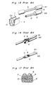
- the tab 21 is integral with the terminals 20. That is, a pair of tabs 21a' and 21b' project horizontally inward from the inner surfaces of both side walls of the core wire-fixing barrel 23 so that the tabs 21a' and 21b' are positioned in the middle of the core wire-fixing barrel 23 in the vertical direction thereof. The interval between the tabs 21a' and 21b' is slight, thus partitioning the space surrounded with the bottom of the core wire-fixing barrel 23 and the side walls thereof into an upper space and a lower space.
- the tabs 21a' and 21b' have serrations 25 and 26 in the form of circular grooves which are formed on the upper and lower surfaces thereof similarly to the first embodiment.
- Two electric wires are inserted into contact with the tabs 21a' and 21b' as follows: One core wire is inserted into the lower space and the other core wire is inserted into the upper space.
- the electric wires can be reliably and easily inserted into the core wire-fixing barrel 23.
- the core wire 8' of the electric wire is inserted into the core wire-fixing barrel 23 and then the tab 21 is placed on the upper side of the core wire 8' and thereafter, the core wire 8 of the electric wire W1 is placed on the upper surface of the tab 21.
- the core wires 8 and 8' are fixed to the core wire-fixing barrel 23 and the electric wires W1 and W2 are fixed to the coating film-fixing barrel 24 by the method previously described.
- a pair of the tabs 21a' and 21b' is formed by partly cutting a middle portion of the core wire-fixing barrel 23 and projecting the cut portion horizontally inward from both side walls of the core wire-fixing barrel 23.
- a pair of the tabs 21a' and 21b' is formed by bending a middle portion of the core wire-fixing barrel 23 so as to project horizontally inward from both side walls thereof.
- inter-connecting terminal An inter-connecting terminal according to a second embodiment will be described below with reference to Figs. 8B and 8C.
- the tab is also integral with the inter-connecting terminal 30.
- a pair of tabs 31a' and 31b' projects inward from the inner surface of both side walls of the barrel.
- the inter-connecting terminal according to this example corresponds to the first embodiment.
- a tab 31a" is formed by bending inward a part of the barrel projecting from the front of the lower portion of one side wall and a tab 31b" is formed by bending inward a part of the barrel projection from the rear of the lower portion of the other side wall.
- the configurations and arrangement of the serrations 25, 26, 32 and 33 formed on the tab and those of the serrations 23a and 34 formed on the core wire-fixing barrel according to the above described embodiments may be modified as shown in Figs. 9A through 9F. That is, the serrations may be arranged at regular intervals horizontally as shown in Fig. 9A or diagonally as shown in Fig. 9B. The configuration thereof may be circular as shown in Fig. 9C; rectangular as shown in Fig. 9D; or cruciform as shown in Fig. 9F. In addition, the serrations may consist of narrow cuts and arranged at random as shown in Fig. 9E.
Landscapes
- Connections Effected By Soldering, Adhesion, Or Permanent Deformation (AREA)
Claims (6)
- Une cosse (20,30) comportant un berceau de fixation d'âme de conducteur (23) qui est approximativement en forme de U en sorte de présenter des parois latérales et sertit l'âme de deux ou plusieurs conducteurs (8, 8') insérés à l'intérieur, ladite cosse comportant :une patte présentant des surfaces supérieure et inférieure portant des dentelures (25, 26) formées sur celles-ci, ladite patte étant disposée le long d'une limite entre lesdites âmes de conducteur de sorte que lesdites dentelures cisaillent un film d'oxyde formé sur lesdites âmes de conducteurs au contact desdites surfaces supérieure et inférieure de ladite patte et retirent ledit film d'oxyde desdites âmes de conducteurs, au moyen de laquelle lesdites âmes de conducteurs sont raccordées électriquement les unes avec les autres par l'intermédiaire de ladite patte; caractérisée en ce que ladite patte fait partie intégrante du berceau de fixation d'âme de conducteur ; etladite patte est constituée d'une paire de pattes (21a', 21b'; 31a', 31b'; 31a", 31b'') se projetant horizontalement vers l'intérieur à partir des surfaces intérieures des deux parois latérales du berceau de fixation d'âme de conducteur et en faisant partie intégrante de sorte que les pattes sont positionnées au milieu du berceau de fixation d'âme de conducteur dans une direction verticale par rapport à celui-ci.
- Une cosse selon la revendication 1, dans laquelle ladite cosse est une cosse pour connecteur (30) comportant ledit berceau de fixation d'âme de conducteur, un berceau de fixation d'une couche de film et une partie destinée au contact électrique.
- Une cosse selon la revendication 1, dans laquelle ladite cosse est une cosse d'interconnexion ou une cosse de raccordement intermédiaire ne comportant que ledit berceau de fixation d'âme de conducteur.
- Une cosse selon la revendication 3, dans laquelle un espace mince existe entre les extrémités de ladite paire de pattes et certaines des âmes des conducteurs sont introduites entre les pattes et une face inférieure de la cosse, et d'autres âmes de conducteurs sont introduites au-dessus de la patte, de sorte que les dentelures cisaillent un film d'oxyde réalisé sur lesdites âmes de conducteurs au contact desdites surfaces supérieure et inférieure des pattes.
- Une cosse selon la revendication 1, dans lequel lesdites dentelures sont des rainures espacées par intervalles sur les surfaces inférieure et supérieure de celle-ci.
- Une cosse selon la revendication 5, dans laquelle lesdites rainures de la patte sont circulaires, rectangulaires ou cruciformes.
Applications Claiming Priority (2)
| Application Number | Priority Date | Filing Date | Title |
|---|---|---|---|
| JP3310770A JPH05152011A (ja) | 1991-11-26 | 1991-11-26 | 圧着端子 |
| JP310770/91 | 1991-11-26 |
Publications (3)
| Publication Number | Publication Date |
|---|---|
| EP0544521A2 EP0544521A2 (fr) | 1993-06-02 |
| EP0544521A3 EP0544521A3 (en) | 1993-12-08 |
| EP0544521B1 true EP0544521B1 (fr) | 1996-09-04 |
Family
ID=18009268
Family Applications (1)
| Application Number | Title | Priority Date | Filing Date |
|---|---|---|---|
| EP92310790A Expired - Lifetime EP0544521B1 (fr) | 1991-11-26 | 1992-11-25 | Terminal pour la connexion de fils |
Country Status (4)
| Country | Link |
|---|---|
| US (2) | US5316506A (fr) |
| EP (1) | EP0544521B1 (fr) |
| JP (1) | JPH05152011A (fr) |
| DE (1) | DE69213405T2 (fr) |
Families Citing this family (69)
| Publication number | Priority date | Publication date | Assignee | Title |
|---|---|---|---|---|
| US5532433A (en) * | 1991-11-13 | 1996-07-02 | Yazaki Corporation | Waterproof-type terminal connection structure and method of producing same |
| DE19549174A1 (de) * | 1995-10-28 | 1997-07-03 | Bosch Gmbh Robert | Kontaktelement mit Crimpabschnitt |
| US5658163A (en) * | 1995-12-19 | 1997-08-19 | Molex Incorporated | Terminal for connecting electrical wires |
| JP3976828B2 (ja) * | 1997-02-17 | 2007-09-19 | 株式会社半導体エネルギー研究所 | 結晶性珪素膜の作製方法 |
| US6842984B1 (en) * | 2000-11-07 | 2005-01-18 | Weed Tiger, Inc. | Grass trimmer cutting line |
| JP2002359048A (ja) * | 2001-05-31 | 2002-12-13 | Canon Inc | 導体の接続方法、導体の接続構造、該接続構造を有する太陽電池モジュール |
| US7252675B2 (en) * | 2002-09-30 | 2007-08-07 | Advanced Cardiovascular, Inc. | Embolic filtering devices |
| CA2461054C (fr) * | 2003-03-27 | 2009-07-07 | Joseph Ludger Bartok | Connecteur electrique |
| FR2865579A1 (fr) * | 2004-01-27 | 2005-07-29 | Framatome Connectors Int | Contact electrique serti a fut ferme, procede de sertissage d'un tel contact, et outil de sertissage correspondant. |
| US7402751B2 (en) * | 2005-10-03 | 2008-07-22 | International Business Machines Corporation | Electrical bifurcated splice |
| JP4568210B2 (ja) * | 2005-11-14 | 2010-10-27 | 矢崎総業株式会社 | 端子金具及び端子付きフラット回路体 |
| JP4818151B2 (ja) * | 2007-02-14 | 2011-11-16 | 株式会社オートネットワーク技術研究所 | 外導体端子及びシールドコネクタ |
| JP2009099266A (ja) * | 2007-10-12 | 2009-05-07 | Yazaki Corp | 同軸ケーブル用シールド端子 |
| JP4922897B2 (ja) * | 2007-11-02 | 2012-04-25 | 株式会社オートネットワーク技術研究所 | 圧着端子、端子付電線及びその製造方法 |
| US7601037B2 (en) * | 2008-01-11 | 2009-10-13 | Hamilton Sundstrand Corporation | Terminal with multiple wire connection |
| JPWO2009101965A1 (ja) * | 2008-02-15 | 2011-06-09 | 株式会社オートネットワーク技術研究所 | 端子金具及びワイヤーハーネス |
| US7686642B2 (en) * | 2008-03-03 | 2010-03-30 | Tempo Industries, Inc. | Wire harness interconnection and retention method and apparatus |
| JP5076072B2 (ja) * | 2008-03-24 | 2012-11-21 | 矢崎総業株式会社 | 圧着端子、及びこの圧着端子を用いた圧着構造 |
| TWD130275S1 (zh) * | 2008-04-08 | 2009-08-11 | 股份有限公司 | 接點元件 |
| JP5400318B2 (ja) * | 2008-04-15 | 2014-01-29 | 矢崎総業株式会社 | アルミ電線用圧着端子 |
| JP5058082B2 (ja) * | 2008-06-18 | 2012-10-24 | 株式会社オートネットワーク技術研究所 | 端子金具及び端子付き電線 |
| JP4996553B2 (ja) * | 2008-06-20 | 2012-08-08 | 株式会社オートネットワーク技術研究所 | 端子金具及び端子付き電線 |
| JP2010021015A (ja) * | 2008-07-10 | 2010-01-28 | Sumitomo Wiring Syst Ltd | 端子金具及び端子付き電線 |
| JP5099225B2 (ja) * | 2008-07-15 | 2012-12-19 | 住友電装株式会社 | 端子金具及び端子金具付き電線 |
| JP5071288B2 (ja) | 2008-07-22 | 2012-11-14 | 住友電装株式会社 | 端子金具および端子金具付き電線 |
| JP5195230B2 (ja) * | 2008-09-26 | 2013-05-08 | 住友電装株式会社 | 端子金具付き電線 |
| JP5394713B2 (ja) * | 2008-12-10 | 2014-01-22 | 矢崎総業株式会社 | 圧着端子 |
| JP4979147B2 (ja) | 2009-04-24 | 2012-07-18 | 株式会社オートネットワーク技術研究所 | 端子金具及び端子金具付き電線 |
| JP5468862B2 (ja) * | 2009-10-02 | 2014-04-09 | 矢崎総業株式会社 | 圧着端子 |
| JP5519382B2 (ja) * | 2010-04-13 | 2014-06-11 | 矢崎総業株式会社 | 圧着端子及びその製造方法 |
| JP5551524B2 (ja) * | 2010-06-21 | 2014-07-16 | 中央発條株式会社 | ステアリング装置および連結ワイヤ |
| JP5690095B2 (ja) * | 2010-08-04 | 2015-03-25 | 矢崎総業株式会社 | 圧着端子 |
| JP5601925B2 (ja) * | 2010-08-05 | 2014-10-08 | 矢崎総業株式会社 | 圧着端子 |
| JP5634789B2 (ja) * | 2010-08-05 | 2014-12-03 | 矢崎総業株式会社 | 圧着端子 |
| JP5601926B2 (ja) * | 2010-08-05 | 2014-10-08 | 矢崎総業株式会社 | 圧着端子 |
| JP5634788B2 (ja) * | 2010-08-05 | 2014-12-03 | 矢崎総業株式会社 | 圧着端子 |
| JP5601233B2 (ja) | 2011-02-07 | 2014-10-08 | 住友電装株式会社 | 端子金具 |
| JP5777357B2 (ja) * | 2011-03-08 | 2015-09-09 | 矢崎総業株式会社 | 圧着端子 |
| WO2013066324A1 (fr) * | 2011-11-02 | 2013-05-10 | Lirette Earl A Iii | Dispositif de borne destiné à relier à la terre un composant électrique à courant continu |
| US8485853B2 (en) | 2011-11-03 | 2013-07-16 | Delphi Technologies, Inc. | Electrical contact having knurl pattern with recessed rhombic elements that each have an axial minor distance |
| US8622774B2 (en) | 2011-11-07 | 2014-01-07 | Delphi Technologies, Inc. | Electrical contact having channel with angled sidewalls and romboid knurl pattern |
| KR101254311B1 (ko) * | 2011-11-28 | 2013-04-12 | 한국단자공업 주식회사 | 터미널 |
| KR101254310B1 (ko) * | 2011-11-28 | 2013-04-12 | 한국단자공업 주식회사 | 터미널 |
| JP5864280B2 (ja) * | 2012-01-18 | 2016-02-17 | 矢崎総業株式会社 | フラット回路体と端子金具との接続方法 |
| US9070992B2 (en) * | 2012-02-16 | 2015-06-30 | Tyco Electronics Corporation | Termination of carbon nanotube macrostructures |
| JP5885346B2 (ja) * | 2012-07-09 | 2016-03-15 | 矢崎総業株式会社 | 圧着端子付きアルミニウム電線および圧着端子付きアルミニウム電線の製造方法 |
| JP6116896B2 (ja) * | 2012-12-27 | 2017-04-19 | 矢崎総業株式会社 | ケーブル |
| US9293233B2 (en) | 2013-02-11 | 2016-03-22 | Tyco Electronics Corporation | Composite cable |
| US9803381B1 (en) * | 2013-03-07 | 2017-10-31 | Homecare Products, Inc. | Ramp and/or platform assembly |
| JP6024609B2 (ja) * | 2013-07-09 | 2016-11-16 | 日立金属株式会社 | 集配電リング |
| JP6146612B2 (ja) * | 2013-07-25 | 2017-06-14 | 株式会社デンソー | 回転電機の固定子 |
| JP6278675B2 (ja) * | 2013-11-28 | 2018-02-14 | 日本航空電子工業株式会社 | 圧着端子及びコネクタ |
| US10128581B2 (en) | 2014-06-19 | 2018-11-13 | Fujikura Ltd. | Crimp terminal |
| JP6363884B2 (ja) * | 2014-06-19 | 2018-07-25 | 株式会社フジクラ | 圧着端子 |
| DE102015209855A1 (de) | 2015-05-28 | 2016-12-01 | Te Connectivity Germany Gmbh | Elektrisches Kontaktierungselement mit einer feinstrukturierten Kontaktierungsfläche |
| DE102015226700A1 (de) * | 2015-12-23 | 2017-06-29 | Robert Bosch Gmbh | Elektrische Verbindungsanordnung zur Verbindung von elektrischen Leitern |
| JP6663714B2 (ja) * | 2015-12-28 | 2020-03-13 | 日本航空電子工業株式会社 | 圧着端子及びコネクタ |
| CN105514636A (zh) * | 2015-12-29 | 2016-04-20 | 苏州卓德电子有限公司 | 一种汽车线束的固定架 |
| CN106981771A (zh) * | 2016-01-19 | 2017-07-25 | 凡甲电子(苏州)有限公司 | 电连接器 |
| DE102017121908B4 (de) | 2017-09-21 | 2023-12-07 | Tdk Electronics Ag | Elektrisches Bauelement mit Litzenkontakt und Verfahren zur Herstellung eines Litzenkontakts |
| DE102017121924B3 (de) * | 2017-09-21 | 2019-02-21 | Tdk Electronics Ag | Elektrisches Bauelement mit Anschlussbereich und Verfahren zur Herstellung eines Anschlussbereichs |
| DE102017131371A1 (de) * | 2017-12-28 | 2019-07-04 | Te Connectivity Germany Gmbh | Mechanisches Verbindungselement, elektrische Kontakteinrichtung sowie elektrischer Verbinder |
| US10581181B1 (en) * | 2018-08-21 | 2020-03-03 | Lear Corporation | Terminal assembly and method |
| JP7074080B2 (ja) * | 2019-01-15 | 2022-05-24 | 住友電装株式会社 | 端子付き電線 |
| JP7345978B2 (ja) * | 2019-09-24 | 2023-09-19 | 矢崎総業株式会社 | 端子付き電線、端子付き電線の製造方法 |
| JP7398971B2 (ja) * | 2020-01-21 | 2023-12-15 | ニッタ株式会社 | ヒーター線の圧着構造および圧着方法 |
| JP7568442B2 (ja) * | 2020-08-06 | 2024-10-16 | 矢崎総業株式会社 | 伝熱構造及びワイヤーハーネス |
| JP7670587B2 (ja) | 2021-09-21 | 2025-04-30 | 日本航空電子工業株式会社 | アンテナ組立体 |
| JP7467516B2 (ja) * | 2022-02-16 | 2024-04-15 | 矢崎総業株式会社 | 圧着端子 |
Family Cites Families (13)
| Publication number | Priority date | Publication date | Assignee | Title |
|---|---|---|---|---|
| GB704091A (en) * | 1951-04-05 | 1954-02-17 | Jean Brandt | Improvements in or relating to couplings or connectors for wires, cables and the like |
| US2724098A (en) * | 1952-04-09 | 1955-11-15 | Thomas & Betts Corp | Electric connectors |
| US3053930A (en) * | 1960-02-04 | 1962-09-11 | Burndy Corp | Electrical connector |
| US3129995A (en) * | 1960-11-14 | 1964-04-21 | Hi Shear Corp | Electrical connector |
| US3156764A (en) * | 1962-03-26 | 1964-11-10 | Jasper Blackburn Corp | Compressible electrical connector with internal deformable ribs |
| US3387080A (en) * | 1966-07-25 | 1968-06-04 | Burndy Corp | Splice connector with locking insert |
| DE1808282C3 (de) * | 1968-11-11 | 1979-07-26 | Karl Pfisterer Elektrotechnischer Spezialartikel Gmbh & Co Kg, 7000 Stuttgart | Preßklemme zum Verbinden zweier elektrischer Leiter |
| US3522365A (en) * | 1968-08-09 | 1970-07-28 | Dennie Dannes | Compressible electrical connector |
| US3715705A (en) * | 1971-03-29 | 1973-02-06 | Thomas & Betts Corp | Multicompartment connector |
| US3777302A (en) * | 1971-11-26 | 1973-12-04 | Amp Inc | Electrical contact terminal having closed entry receptacle and connector |
| FR2214178B1 (fr) * | 1973-01-11 | 1976-08-27 | Thomas & Betts Corp | |
| US3989339A (en) * | 1975-10-02 | 1976-11-02 | Thomas & Betts Corporation | Electrical connector and method of making same |
| DE3043209C2 (de) * | 1980-11-15 | 1983-01-05 | Minnesota Mining and Manufacturing Co., 55133 Saint Paul, Minn. | Preßverbinder für elektrische Leitungen |
-
1991
- 1991-11-26 JP JP3310770A patent/JPH05152011A/ja active Pending
-
1992
- 1992-11-20 US US07/979,223 patent/US5316506A/en not_active Expired - Fee Related
- 1992-11-25 EP EP92310790A patent/EP0544521B1/fr not_active Expired - Lifetime
- 1992-11-25 DE DE69213405T patent/DE69213405T2/de not_active Expired - Fee Related
-
1993
- 1993-11-22 US US08/155,324 patent/US5370560A/en not_active Expired - Fee Related
Also Published As
| Publication number | Publication date |
|---|---|
| EP0544521A3 (en) | 1993-12-08 |
| JPH05152011A (ja) | 1993-06-18 |
| US5370560A (en) | 1994-12-06 |
| DE69213405D1 (de) | 1996-10-10 |
| EP0544521A2 (fr) | 1993-06-02 |
| US5316506A (en) | 1994-05-31 |
| DE69213405T2 (de) | 1997-03-13 |
Similar Documents
| Publication | Publication Date | Title |
|---|---|---|
| EP0544521B1 (fr) | Terminal pour la connexion de fils | |
| US4990110A (en) | Electrical contact arrangement | |
| US5541365A (en) | Beam Welding Terminal Structure | |
| EP0517077A2 (fr) | Contact électrique | |
| US5310353A (en) | Electrical power distribution center having conductive ridges | |
| US10938125B2 (en) | Connection terminal and terminal connection structure | |
| GB2124041A (en) | Insulation displacement terminal for an electrical connector and environmental sealing means therefor | |
| EP0201512B1 (fr) | Procede et produit selectionnes de terminaison de fentes par brasure | |
| EP0614247B1 (fr) | Méthode pour joindre des fils électriques | |
| US3768062A (en) | Terminal for flexible circuits | |
| EP0720256A1 (fr) | Boîte de raccordement électrique et borne de liaison utilisée avec une telle boîte | |
| EP1089383B1 (fr) | Organe de contact pour connecteurs et méthode de fabrication | |
| JP3546479B2 (ja) | 大電流接続用ターミナルおよび該ターミナルを用いた電気接続箱の接続構造 | |
| EP0102156B1 (fr) | Borne de raccordement à déplacement d'isolant pour un connecteur électrique et moyens assurant son étanchéité par rapport au milieu environnant | |
| US5362242A (en) | Junction box and terminal to be used in the junction box | |
| US5584729A (en) | Electrical outlet adapter | |
| JP2001076779A (ja) | 分岐接続器 | |
| JP2947079B2 (ja) | 電気接続箱の接続構造 | |
| JPH0638338A (ja) | ブスバーと電線の圧接構造 | |
| US4983128A (en) | Bus bar for making electrical taps | |
| EP0152690B1 (fr) | Assemblage pour connecteur multi-conducteur à déplacement d'isolant | |
| JP3087617B2 (ja) | 圧接端子を備えた電気接続箱 | |
| EP0402792A2 (fr) | Socle électrique avec une fiche en forme de lame | |
| JPH0451425Y2 (fr) | ||
| JPS63164178A (ja) | 電気接触子 |
Legal Events
| Date | Code | Title | Description |
|---|---|---|---|
| PUAI | Public reference made under article 153(3) epc to a published international application that has entered the european phase |
Free format text: ORIGINAL CODE: 0009012 |
|
| AK | Designated contracting states |
Kind code of ref document: A2 Designated state(s): DE GB |
|
| PUAL | Search report despatched |
Free format text: ORIGINAL CODE: 0009013 |
|
| AK | Designated contracting states |
Kind code of ref document: A3 Designated state(s): DE GB |
|
| 17P | Request for examination filed |
Effective date: 19940603 |
|
| 17Q | First examination report despatched |
Effective date: 19941212 |
|
| GRAH | Despatch of communication of intention to grant a patent |
Free format text: ORIGINAL CODE: EPIDOS IGRA |
|
| GRAH | Despatch of communication of intention to grant a patent |
Free format text: ORIGINAL CODE: EPIDOS IGRA |
|
| GRAA | (expected) grant |
Free format text: ORIGINAL CODE: 0009210 |
|
| AK | Designated contracting states |
Kind code of ref document: B1 Designated state(s): DE GB |
|
| REF | Corresponds to: |
Ref document number: 69213405 Country of ref document: DE Date of ref document: 19961010 |
|
| PLBE | No opposition filed within time limit |
Free format text: ORIGINAL CODE: 0009261 |
|
| 26N | No opposition filed | ||
| PGFP | Annual fee paid to national office [announced via postgrant information from national office to epo] |
Ref country code: GB Payment date: 19981127 Year of fee payment: 7 |
|
| PGFP | Annual fee paid to national office [announced via postgrant information from national office to epo] |
Ref country code: DE Payment date: 19981207 Year of fee payment: 7 |
|
| PG25 | Lapsed in a contracting state [announced via postgrant information from national office to epo] |
Ref country code: GB Free format text: LAPSE BECAUSE OF NON-PAYMENT OF DUE FEES Effective date: 19991125 |
|
| GBPC | Gb: european patent ceased through non-payment of renewal fee |
Effective date: 19991125 |
|
| PG25 | Lapsed in a contracting state [announced via postgrant information from national office to epo] |
Ref country code: DE Free format text: LAPSE BECAUSE OF NON-PAYMENT OF DUE FEES Effective date: 20000901 |