EP0544982A1 - Appareil d'écriture - Google Patents
Appareil d'écriture Download PDFInfo
- Publication number
- EP0544982A1 EP0544982A1 EP92110916A EP92110916A EP0544982A1 EP 0544982 A1 EP0544982 A1 EP 0544982A1 EP 92110916 A EP92110916 A EP 92110916A EP 92110916 A EP92110916 A EP 92110916A EP 0544982 A1 EP0544982 A1 EP 0544982A1
- Authority
- EP
- European Patent Office
- Prior art keywords
- leg
- writing device
- holder
- legs
- carriage
- Prior art date
- Legal status (The legal status is an assumption and is not a legal conclusion. Google has not performed a legal analysis and makes no representation as to the accuracy of the status listed.)
- Withdrawn
Links
- 238000004804 winding Methods 0.000 claims abstract description 14
- 239000003302 ferromagnetic material Substances 0.000 claims abstract description 4
- 230000008859 change Effects 0.000 claims description 2
- 238000005259 measurement Methods 0.000 abstract 1
- 230000005291 magnetic effect Effects 0.000 description 9
- 230000004907 flux Effects 0.000 description 5
- 241001422033 Thestylus Species 0.000 description 3
- 238000010276 construction Methods 0.000 description 2
- 230000004044 response Effects 0.000 description 2
- 230000004913 activation Effects 0.000 description 1
- 230000009849 deactivation Effects 0.000 description 1
- 230000002349 favourable effect Effects 0.000 description 1
- 238000000034 method Methods 0.000 description 1
- 230000008569 process Effects 0.000 description 1
- 230000003068 static effect Effects 0.000 description 1
- 230000003313 weakening effect Effects 0.000 description 1
Images

Classifications
-
- G—PHYSICS
- G01—MEASURING; TESTING
- G01D—MEASURING NOT SPECIALLY ADAPTED FOR A SPECIFIC VARIABLE; ARRANGEMENTS FOR MEASURING TWO OR MORE VARIABLES NOT COVERED IN A SINGLE OTHER SUBCLASS; TARIFF METERING APPARATUS; MEASURING OR TESTING NOT OTHERWISE PROVIDED FOR
- G01D15/00—Component parts of recorders for measuring arrangements not specially adapted for a specific variable
- G01D15/22—Chopper bars for bringing recording element into contact with recording surface
Definitions
- the invention relates to a writing device for recording measured values, in particular alphanumeric data, on a recording medium, with a writing head having a writing pen, which is movably arranged by means of a holder on a carriage movable transversely to the recording medium and can be actuated by means of electrical pulses,
- the Bracket consists of two, essentially parallel to each other and at one end interconnected legs of ferromagnetic material, one of which is attached to the carriage and the other carries the writing head at its free end, the bracket further being fed with the electrical pulses Winding is provided and in the area of the print head between the two legs there is a narrowing forming an air gap, according to patent no. (Application no. P 40 20 147.3).
- one leg of the holder is covered by a winding.
- a magnetic flux is generated in the two legs, which strives to reduce the air gap between the two legs and thus pull the movable leg towards the fixed leg and in this way press the writing head with the stylus onto the recording medium .
- the magnitude of the magnetic force that can be generated by the winding is limited, so that the force lifting the movable leg from the recording medium may only be of a limited size.
- the legs of the bracket are resiliently biased away from each other and the winding is an annular or cylindrical coil which encloses a coil core and with its winding plane approximately parallel to a leg of the bracket on the surface facing the second leg of this first leg is arranged.
- the toroidal or cylindrical coil can generate considerably higher magnetic forces at the same current, which not only cause the pen to move faster on the recording medium, but also allow a considerable resilient biasing force acting in opposite directions on the movable leg, which allows the pen to be lifted quickly Pen leads from the record carrier. This enables an increased write speed.
- the ring or solenoid can be inserted into a cup-shaped receptacle of the slide for simple assembly.
- the coil core can be cup-shaped and its bottom can rest on the first leg carrying the toroidal or cylindrical coil, the pot opening facing the second leg.
- the losses are kept low if the armature has a cylindrical cross section with a slightly smaller diameter than the diameter of the pot opening of the coil core.
- the holder consists of a one-piece, U-shaped leaf spring, the legs of which are biased to move away from each other and on the facing surfaces of which the ring or solenoid coil with the coil core or the armature are arranged, the one-piece design results in unnecessary weakening of magnetic flux avoided. Furthermore, the leaf spring not only fulfills the function of the holder and the component that conducts the magnetic flux, but also the function of the return spring. There is therefore no need for an additional spring component.
- the U-shaped leaf spring thus combines a multitude of functions in a single simple component.
- the movement path of the legs away from one another can be limited by a stop.
- the stop is preferably arranged on the carriage or on the leg of the holder fastened to the carriage and engages in a captivating manner around the other leg.
- a simple adjustment of the air gap is possible in that the stop is adjustable to change the distance between the legs.
- the stop can be a screw with the free end of the threaded shaft in a threaded bore of the slide or the slide hen leg can be screwed in while it projects with its other end of the threaded shaft through a recess of the leg remote from the slide and at this end has a screw head of greater radial extension than the recess.
- the screw consists of a plastic, it is secured against automatic adjustment on the one hand without additional measures. On the other hand, it also forms a damped stop with its screw head.
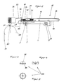
- the writing device consists of a carriage 1, which slides on two guide rods 2 and 3, which are attached to two side parts 4 and 5 of a line recorder.
- the guide rod 2 passes through two bearing eyes 6 and 7 arranged on the slide 1.
- the slide is secured against rotation by the guide rod 3 and guide grooves 8 on the rear part of the slide.
- the movement of the carriage takes place by means of a cable drive, which consists of a traction cable 9 which is fastened to the underside of the carriage by means of screws and which wraps around three cable pulleys 11, 12 and 13.
- the pulley 13 is driven by a stepper motor 14 which moves the carriage 1 precisely in its respective position.
- the holder 15 which consists of a U-shaped leaf spring 16 which has two legs 17 and 18. On the leg 18 two mounting tabs 19 and 20 are formed, by means of which and the associated screws, the leaf spring 16 is attached to the carriage.
- a pot-shaped receptacle 10 is formed on the slide 1, into which a solenoid 21 is inserted, the winding plane of which is oriented approximately parallel to the legs 17 and 18.
- the solenoid 21 encloses a coil core 23, which is pot-shaped and has its pot opening 33 facing the leg 17. With its bottom 35, the coil core 23 rests on the leg 18.
- the ring wall of the pot-shaped coil core 23 is cut symmetrically obliquely at the area facing the pot opening, so that the coil core 23 has a roof-like tapering cross-section.
- An armature 32 with a cylindrical cross-section is fastened to the leg 17 coaxially to the solenoid coil 21 and projects into the pot opening 33 of the coil core 23 and has a slightly smaller diameter than the pot opening 33 of the coil core 23. As a result, an air gap 24 is formed between the coil core 23 and armature 32.
- the carriage 1 is provided with a threaded bore 36, into which a screw 25 made of plastic is screwed with the free end of its threaded shaft.
- the screw 25 protrudes with the other end of its threaded shaft through a transverse recess of the leg 17 and has at this free end a screw head 34 of greater radial extension than the recess in the leg 17.
- the screw head 34 thus forms a stop limiting the distance between the legs 17 and 18.
- the leaf spring 16 is tied up by the screw head 34 in such a way that the freely pivotable leg 17 abuts the screw head 34 with pre-tension when the solenoid 21 is not energized.
- the write head 26 which is designed in the form of an ink cartridge, sits on the free end 22 of the leg 17.
- the ink cartridge carries a pen 27 which is directed against a roller-like writing pad 28.
- the write head 26 is secured with locking means 29 on the free end of the leg 17.
- roller-like writing pad 28 which is aligned parallel to the guide rods 2 and 3 of the writing device, there is a groove 30 in the impact area of the writing pen 27, which allows the recording medium 31 to escape during the writing process, thereby avoiding a static overdetermination of the system.
- the record carrier is advanced transversely to the sliding movement of the carriage 1, so that when the new position of the record carrier has been reached, a new series of points are recorded can.
Landscapes
- Physics & Mathematics (AREA)
- General Physics & Mathematics (AREA)
Applications Claiming Priority (2)
| Application Number | Priority Date | Filing Date | Title |
|---|---|---|---|
| DE19914140298 DE4140298A1 (de) | 1990-06-25 | 1991-12-06 | Schreibeinrichtung |
| DE4140298 | 1991-12-06 |
Publications (1)
| Publication Number | Publication Date |
|---|---|
| EP0544982A1 true EP0544982A1 (fr) | 1993-06-09 |
Family
ID=6446463
Family Applications (1)
| Application Number | Title | Priority Date | Filing Date |
|---|---|---|---|
| EP92110916A Withdrawn EP0544982A1 (fr) | 1991-12-06 | 1992-06-27 | Appareil d'écriture |
Country Status (1)
| Country | Link |
|---|---|
| EP (1) | EP0544982A1 (fr) |
Citations (5)
| Publication number | Priority date | Publication date | Assignee | Title |
|---|---|---|---|---|
| GB648276A (en) * | 1947-03-27 | 1951-01-03 | Yarnall Waring Co | Improvements in recording apparatus |
| GB2108722A (en) * | 1981-11-03 | 1983-05-18 | Hewlett Packard Co | Pen-lift system |
| EP0096085A1 (fr) * | 1982-06-04 | 1983-12-21 | Ibm Deutschland Gmbh | Dispositif pour serrer une tête d'impression munie d'une électrode d'écriture |
| DE3711862A1 (de) * | 1986-12-03 | 1988-06-09 | Dia Nielsen Gmbh | Druck-schreibeinrichtung |
| EP0463235A1 (fr) * | 1990-06-25 | 1992-01-02 | Sensycon Gesellschaft Für Industrielle Sensorsysteme Und Prozessleittechnik Mbh | Dispositif d'inscription pour l'enregistrement de mesures, en particulier de données alphanumériques |
-
1992
- 1992-06-27 EP EP92110916A patent/EP0544982A1/fr not_active Withdrawn
Patent Citations (5)
| Publication number | Priority date | Publication date | Assignee | Title |
|---|---|---|---|---|
| GB648276A (en) * | 1947-03-27 | 1951-01-03 | Yarnall Waring Co | Improvements in recording apparatus |
| GB2108722A (en) * | 1981-11-03 | 1983-05-18 | Hewlett Packard Co | Pen-lift system |
| EP0096085A1 (fr) * | 1982-06-04 | 1983-12-21 | Ibm Deutschland Gmbh | Dispositif pour serrer une tête d'impression munie d'une électrode d'écriture |
| DE3711862A1 (de) * | 1986-12-03 | 1988-06-09 | Dia Nielsen Gmbh | Druck-schreibeinrichtung |
| EP0463235A1 (fr) * | 1990-06-25 | 1992-01-02 | Sensycon Gesellschaft Für Industrielle Sensorsysteme Und Prozessleittechnik Mbh | Dispositif d'inscription pour l'enregistrement de mesures, en particulier de données alphanumériques |
Similar Documents
| Publication | Publication Date | Title |
|---|---|---|
| DE2346449C3 (de) | Einrichtung zur Steuerung der Vertikalbewegung eines Schreibstiftes in einem automatischen Zeichengerät oder dergleichen | |
| EP1348104B1 (fr) | Palpeur pour appareil de mesure de coordonnees | |
| DE2908235C2 (de) | Vorrichtung an einer Einspritzpumpe mit einer Regelstange zur Einstellung der Fördermenge von Brennstoff für den Betrieb einer Brennkraftmaschine | |
| DE2229394C2 (de) | Elektromagnetische Antriebsvorrichtung für ein hin- und herbewegbares Getriebeglied | |
| DE2516639B2 (de) | Spannungsregler für den Oberfaden einer Nähmaschine | |
| DE3524634C2 (fr) | ||
| DE2027760A1 (fr) | ||
| DE3047712A1 (de) | Gleichstrom-hubmagnet | |
| EP0544982A1 (fr) | Appareil d'écriture | |
| EP0463235B1 (fr) | Dispositif d'inscription pour l'enregistrement de mesures, en particulier de données alphanumériques | |
| DE3116402C2 (de) | Rückprallarmes Tauchankermagnetsystem | |
| DE4140298A1 (de) | Schreibeinrichtung | |
| DE2165538A1 (de) | Vorrichtung zur steuerung der bewegungen einer flachstrickmaschine | |
| EP1397948B1 (fr) | Dispositif de mise en place et procede pour mettre des objets en place sur des substrats | |
| DE2230946A1 (de) | Vorrichtung zur Verstellung von Magnetköpfen | |
| DE2131424B2 (de) | Verfahren und Einrichtung zur Verhinderung des Zurückprellens eines in einem konstanten Magnetfeld hin- und herbeweglichen Tauchspulenankers von mindestens einem Wegbegrenzungsanschlag | |
| DE3022734A1 (de) | Vorrichtung zum verstellen einer andrueckrolle und eines magnetkopfes eines magnetband-aufzeichnungsgeraetes | |
| DD142316A1 (de) | Druckmagneteinheit fuer den typendruck in seriendruckwerken | |
| DE2953477C2 (fr) | ||
| DE946014C (de) | Filterhebelanordnung bei den Laufwerken von Magnetbandgeraeten | |
| DE2141264C3 (de) | Elektromagnetisch betätigtes Brennstoffeinspritzventil für Brennkraftmaschinen | |
| DE3689468T2 (de) | Elektrische Fernschalter. | |
| EP2133715A1 (fr) | Dispositif et procédé destinés à la déviation d'un rayonnement électromagnétique, en particulier d'un rayon laser | |
| DE3147449C2 (de) | Elektrodynamische Anschlagvorrichtung für ein Druckwerk in Schreib- oder ähnlichen Büromaschinen | |
| DE976560C (de) | Elektromagnetischer PI-Regler mit einer Reglerfeder |
Legal Events
| Date | Code | Title | Description |
|---|---|---|---|
| PUAI | Public reference made under article 153(3) epc to a published international application that has entered the european phase |
Free format text: ORIGINAL CODE: 0009012 |
|
| AK | Designated contracting states |
Kind code of ref document: A1 Designated state(s): CH DE FR GB IT LI SE |
|
| 17P | Request for examination filed |
Effective date: 19930721 |
|
| 17Q | First examination report despatched |
Effective date: 19931112 |
|
| STAA | Information on the status of an ep patent application or granted ep patent |
Free format text: STATUS: THE APPLICATION IS DEEMED TO BE WITHDRAWN |
|
| 18D | Application deemed to be withdrawn |
Effective date: 19960102 |
|
| K1C1 | Correction of patent application (title page) published |
Effective date: 19930609 |