EP0544997A1 - Dispositif pour tenir un tampon et tampon - Google Patents
Dispositif pour tenir un tampon et tampon Download PDFInfo
- Publication number
- EP0544997A1 EP0544997A1 EP92113379A EP92113379A EP0544997A1 EP 0544997 A1 EP0544997 A1 EP 0544997A1 EP 92113379 A EP92113379 A EP 92113379A EP 92113379 A EP92113379 A EP 92113379A EP 0544997 A1 EP0544997 A1 EP 0544997A1
- Authority
- EP
- European Patent Office
- Prior art keywords
- stopper
- stopper rod
- rod
- stop surface
- support surface
- Prior art date
- Legal status (The legal status is an assumption and is not a legal conclusion. Google has not performed a legal analysis and makes no representation as to the accuracy of the status listed.)
- Granted
Links
Images


Classifications
-
- B—PERFORMING OPERATIONS; TRANSPORTING
- B22—CASTING; POWDER METALLURGY
- B22D—CASTING OF METALS; CASTING OF OTHER SUBSTANCES BY THE SAME PROCESSES OR DEVICES
- B22D41/00—Casting melt-holding vessels, e.g. ladles, tundishes, cups or the like
- B22D41/14—Closures
- B22D41/16—Closures stopper-rod type, i.e. a stopper-rod being positioned downwardly through the vessel and the metal therein, for selective registry with the pouring opening
- B22D41/18—Stopper-rods therefor
Definitions
- the invention relates to an invention for holding a refractory, ceramic stopper, in a metallurgical vessel, on a stopper rod which projects into an installation space of the stopper and is fixed therein.
- the invention also relates to a stopper for such a device.
- the stopper rod is usually also used to supply gas to the stopper.
- EP 0 358 535 A2 is intended to ensure that sealing surfaces of the plug and the plug rod are struck after the plug rod has been screwed into the threaded piece. This is only possible if the longitudinal axis of the threaded sleeve and the longitudinal axis of the plug rod are exactly coaxial. In practice, such coaxiality is difficult to achieve. So leaks can occur. Leakages can also occur because when a provided nut is tightened, the sealing surface of the plug rod tends to lift off the sealing surface of the plug, since the threaded connection inevitably has play.
- Leakages can also result from the different thermal expansion coefficients of the ceramic of the stopper on the one hand and the metal of the stopper rod on the other hand. As a result, cracks can form in the ceramic material.
- the object of the invention is to propose a device of the type mentioned in the introduction, in which the stopper is held on the stopper rod while avoiding a threaded connection. It is also an object of the invention to provide such a stopper.
- the above object is achieved in a device of the type mentioned in that an expansion of the installation space forms a stop surface and a support surface is formed on the stopper rod, that spreading segments with their upper edge on the stop surface in the stopper and with their lower edge on the support surface of the stopper rod rest and thereby hold the stopper on the stopper rod and that the expansion segments fold into the extension when inserting the stopper rod into the installation space.
- the plug rod and the plug do not need to be rotated against one another during assembly. This makes assembly easier. During assembly, the plug rod must only be pushed axially into the plug. As soon as the expansion segments reach the area of the extension, they fold in front of the stop surface. The stopper can then no longer be removed from the stopper rod.
- a disc is provided on the stopper rod, which can be pressed against the end face of the stopper by means of a thread of the stopper rod.
- the spreading segments are firmly clamped between the stop surface and the support surface by the pressure of the disc acting on the end face.
- the disc itself can be guided on the plug rod with an internal thread.
- the disk is preferably pressed against the end face of the stopper by means of a nut guided on the thread of the stopper rod.
- a sealing packing is provided between the disc and the end face.
- the spreading segments preferably fold into the extension under restoring force. For this, it is sufficient to provide a spring ring encompassing the expansion segments.
- the restoring force only needs to be given during assembly. It is therefore not a problem if the restoring force is lost during the operation of the stopper, since the spreading segments are clamped between the stop surface and the support surface after being unfolded.
- a stopper for the device of the type mentioned is characterized in that it has an extension in its installation space, which forms a stop surface for spreading segments.
- the simple structure and ease of assembly are advantageous. It is also favorable that the stopper rod does not have to have tightly toleranced designs in order to be able to be used for the stopper.
- the expansion of the plug does not have to be very large, so that it weakens the plug only slightly and the steel parts, namely the plug rod and the expansion segments, can be used several times.
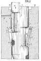
- a stopper (1) made of refractory, ceramic material has an installation space (2) for a stopper rod (3).
- the stopper rod (3) can be tubular and form a channel (4) for guiding purge gas through the stopper (1) into the melt of the metallurgical vessel (not shown).
- An extension (5) is formed in the installation space (2), which forms an annular stop surface (6).
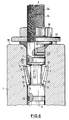
- the stop surface (6) can lie in a plane radial to the longitudinal axis (L) (cf. FIG. 1). However, it can also be slightly conical (see FIG. 3).
- the extension (5) is wedge-shaped in profile. It tapers from the stop surface (6) to the diameter of the installation space (2) necessary for the insertion of the plug rod (3). Overall, the extension (5) weakens the stopper (1) only slightly.
- the stopper rod (3) is provided with a cylindrical taper (7). This forms a conical support surface (8).
- Spreading segments (9) are provided between the support surface (8) and the stop surface (6). If, for example, three expansion segments (9) are provided, then they each do not extend by more than 120 ° around the circumference of the stopper rod (3). If four expansion segments (9) are provided, then each expansion segment (9) extends by approximately 90 ° around the circumference of the stopper rod (3).
- the expansion segments (9) are made of steel. However, they can also consist of other, in particular ceramic, materials that can withstand the operating temperatures that occur.
- Each spreading segment (9) forms an upper edge (10) which is assigned to the stop surface (6) and a lower edge (11) which is assigned to the support surface (8).
- Each spreading segment (9) has a bevel (12) so that a tilting line (13) resting on the taper (7) is formed.
- the spreading segments (9) are surrounded on the outside by a spring ring, for example a rubber ring (14).
- the spring ring (14) engages between the tilt line (13) and the lower edge (11) on the expansion segments (9).
- the lower edges (11) lie flat against the support surface (8).
- a flat power transmission between the expansion segments (9) and the plug rod (3) is thereby achieved.
- the bevels (12) rest on the taper (7).
- the angle (a) of the bevel (12) is approximately equal to the angle (b) of the conical support surface (8).
- the angles (a, b) are each about 15 °. However, they can easily be larger or smaller than 15 °, namely between 5 ° and 30 °.
- the upper edges (10) do not lie flat against the stop surface (6).
- the stopper rod (3) is provided with an external thread (15) that carries a nut (16). By means of the nut (16), a washer (17) is pressed against the end face (18) of the stopper (1).
- an annular sealing packing (19) is arranged between the disc (17) and the end face (18). This is highly temperature-resistant and consists, for example, of ceramic fibers or glass fibers which are impregnated with graphite, molybdenum, water glass or the like.
- a recess (20) is provided on the end face (18), which runs around the stopper rod (3) and in which the sealing packing (19) is also located.
- the depression (20) can be conical or stepped.
- An annular seal (22) is arranged on the stopper rod (3) below the support surface (8).
- a channel (23) is formed in the stopper (1) and opens into the space between the seals (19, 22).
- a pressure line (24) is connected to channel (23) through which inert gas is pressed into the space between the seals (19, 22) under pressure.
- a pressure gauge (25) is connected to the pressure line (24) and indicates the pressure prevailing in the space between the seals (19, 22). As long as the pressure gauge (25) shows the setpoint value of the pressure, this is a sign that the seals (19, 22) are effective, ie no oxygen can get into the melt. If the pressure drops, this can be read on the manometer (25). In this case, the seals (19 and / or 22) are replaced, since the drop in pressure is a sign that the seals (19, 22) are no longer sufficiently tight, so that oxygen may leak out through the seal (19) the environment is sucked into the melt.
- the distance (L1) of the end face (18) from the stop edge (6) is not less than the length (L2) of the expansion segments (9). It is achieved on the one hand that the stopper (1) above the stop surface (6) is sufficiently stable. On the other hand, there is some compensation for the thermal expansion in the direction of the longitudinal axis (L).
- the assembly of the described device is done approximately as follows:
- the expansion segments (9) are attached to the taper rod (3) which is still free of the plug (1) and held together by means of the spring ring (14). You are in the position folded out about the tilt line (13).
- the plug rod (3) is then pushed into the installation space (2) of the plug (1) in the direction of arrow (A).
- the spreading segments (9) first pivot into the taper (7). If the upper edge (10) then comes into the area of the extension (5) when the insert is pushed in further, the expansion segments (9) pivot under the action of the spring washer (14) in front of the stop surface (6) until the bevels (12) of the expansion segments ( 9) rest in the area of the taper (7) on the plug rod (3).
- the plug rod (3) is pushed into the plug (1), it is not important that the plug (1) and the plug rod (3) are in a particular rotational position related to the longitudinal axis (L).
- the sealing packing (19) is then pressed firmly against the end face (18) by means of the nut (16) over the washer (17).
- the expansion segments (9) are firmly clamped between the support surface (8) and the stop surface (6).
- the stopper (1) is thus held tightly and firmly on the stopper rod (3).
- the holder does not loosen if the spring ring (14) loses its spring force. If the stopper (1) is worn out, it can be knocked off the stopper rod (3) and a new stopper can be placed on it in the manner described.
- edge (21) between the stop surface (6) and the installation space (2). educated.
- the edge (21) prevents the expansion segment (9) from folding back into the taper (7) after it has been pressed against the stop surface (6). Such a folding back could otherwise take place when the contact pressure of the sealing packing (19) decreases, the spring ring (14) is ineffective and vibrations occur.
- FIG. 4 shows a partial view of the stopper rod (3) and the stopper (1) in the region of its stop surface (6).
- the spreading segment (9) is shown in several stages of its pivoting out.
- the upper edge (10) of the expansion segment (9) is bevelled in this case so that it lies parallel to the radial stop surface (6) in the pivoted-out position of the expansion segment (9), so that when the plug rod (3) is tightened, a flat surface is formed Contact of the upper edge (10) on the stop surface (6) results. It is constructively favorable that the stop surface (6) only has to extend radially.
- the flat contact of the upper edge (10) on the stop surface (6) prevents the expansion segment (9) or one of the expansion segments (9) from undesirably folding back.
- the support surface (8) of the plug rod (3) is designed beveled. However, this is not necessary. It is also possible to make the support surface (8) perpendicular to the longitudinal axis (L), radially. In this case, the lower edge (11) and the bevel (12) of the expansion segment (9) are formed as shown in FIG. 5. The spreading segment (9) is shown in FIG shown in its swung-out state. The lower edge (11) is flat on the support surface (8). The bevel (12) lies flat against the taper (7).
- the simple design of the support surface (8) is particularly advantageous. In addition, there is a favorable power transmission between the expansion segments (9) of the stopper rod (3) in the tensioned state.
- the holding device according to FIG. 6 differs from the holding device according to FIG. 1 only in that the gas supply channel (23) is not through a hole in the stopper (1) itself, but through an axial hole (27) and one or more radial holes (23). is formed in the stopper rod (3).
- the gas supply line (24) with the pressure gauge (25) is connected to the axial bore (27).
- the sealing arrangement (19, 22) is identical to the sealing arrangement according to FIG. 1.
- both ring seals (19, 26) can be arranged above the expansion segments (9), in which case the ring seal (22) can be omitted.
- the latter sealing arrangement can also be used in connection with the gas supply arrangement according to FIG. 1. It is only important that the channel (23) opens between the two ring seals (19, 26).
Landscapes
- Engineering & Computer Science (AREA)
- Mechanical Engineering (AREA)
- Gasket Seals (AREA)
- Furnace Housings, Linings, Walls, And Ceilings (AREA)
- Casting Support Devices, Ladles, And Melt Control Thereby (AREA)
- Supplying Of Containers To The Packaging Station (AREA)
- Load-Engaging Elements For Cranes (AREA)
Applications Claiming Priority (4)
| Application Number | Priority Date | Filing Date | Title |
|---|---|---|---|
| DE4138812 | 1991-11-26 | ||
| DE4138812 | 1991-11-26 | ||
| DE4212450A DE4212450A1 (de) | 1991-11-26 | 1992-04-14 | Einrichtung zum halten eines stopfens und stopfen |
| DE4212450 | 1992-04-14 |
Publications (2)
| Publication Number | Publication Date |
|---|---|
| EP0544997A1 true EP0544997A1 (fr) | 1993-06-09 |
| EP0544997B1 EP0544997B1 (fr) | 1997-11-19 |
Family
ID=25909498
Family Applications (1)
| Application Number | Title | Priority Date | Filing Date |
|---|---|---|---|
| EP92113379A Expired - Lifetime EP0544997B1 (fr) | 1991-11-26 | 1992-08-06 | Dispositif pour tenir un tampon et tampon |
Country Status (4)
| Country | Link |
|---|---|
| US (1) | US5303905A (fr) |
| EP (1) | EP0544997B1 (fr) |
| AT (1) | ATE160305T1 (fr) |
| DE (2) | DE4212450A1 (fr) |
Cited By (2)
| Publication number | Priority date | Publication date | Assignee | Title |
|---|---|---|---|---|
| WO1995003145A1 (fr) * | 1993-07-23 | 1995-02-02 | Burkhard Labod | Systeme permettant de relier une quenouille de cuve metallurgique a son dispositif de levage, quenouille appropriee au systeme et procede de production dudit systeme |
| WO1998000255A1 (fr) * | 1996-07-02 | 1998-01-08 | Foseco International Limited | Quenouille |
Families Citing this family (7)
| Publication number | Priority date | Publication date | Assignee | Title |
|---|---|---|---|---|
| US5381103A (en) * | 1992-10-13 | 1995-01-10 | Cree Research, Inc. | System and method for accelerated degradation testing of semiconductor devices |
| DE4313427C1 (de) * | 1993-04-26 | 1994-08-18 | Labod Burkhard | Anordnung zur Verbindung einer Stopfenstange für ein metallurgisches Gefäß mit ihrer Hebevorrichtung und für die Anordnung geeignete Stopfenstange sowie Verfahren zur Herstellung der Anordnung |
| DE19823988C2 (de) * | 1998-05-29 | 2000-07-20 | Didier Werke Ag | Stopfen für den Verschluß von Metallschmelze aufnehmenden Behältnissen |
| EP1618975B1 (fr) * | 2004-07-22 | 2007-02-07 | Refractory Intellectual Property GmbH & Co. KG | Quenouille à corps allongé |
| GB0507939D0 (en) * | 2005-04-20 | 2005-05-25 | Foseco Int | Stopper red |
| NZ701215A (en) * | 2012-05-18 | 2016-08-26 | Vesuvius Crucible Co | Purge plug |
| BR202017000379Y1 (pt) * | 2016-01-10 | 2022-04-26 | Amsted Rail Company, Inc | Mecanismo de fixação de bastão de encaixe metálico de derramamento para rodas de aço fundido |
Citations (4)
| Publication number | Priority date | Publication date | Assignee | Title |
|---|---|---|---|---|
| AT36259B (de) * | 1907-05-07 | 1909-02-10 | Manufacturers Machine Co | Sohlenschlitzmaschine. |
| US2987787A (en) * | 1959-10-15 | 1961-06-13 | Joseph Dixon Crucible Co | Stopper rod assemblies |
| AT249895B (de) * | 1965-02-17 | 1966-10-10 | Vesuvius Crucible Co | Stopfen für eine Gießpfanne oder einen ähnlichen Behälter |
| DE4032454A1 (de) * | 1990-10-12 | 1992-04-16 | Didier Werke Ag | Einrichtung zum halten eines stopfens bei einem metallurgischen gefaess und stopfen fuer eine solche einrichtung |
Family Cites Families (5)
| Publication number | Priority date | Publication date | Assignee | Title |
|---|---|---|---|---|
| US1843175A (en) * | 1929-08-28 | 1932-02-02 | Corning Glass Works | Refractory article |
| US2005311A (en) * | 1934-07-06 | 1935-06-18 | American Sheet & Tin Plate | Stopper rod for ladles |
| US2587110A (en) * | 1949-11-23 | 1952-02-26 | Carter Edwin William | Bottom tap ladle mechanism |
| JPS613656A (ja) * | 1984-06-19 | 1986-01-09 | Honda Motor Co Ltd | 底注ぎ取鍋 |
| US4946083A (en) * | 1988-12-29 | 1990-08-07 | Vesuvius Crucible Company | One-piece stopper rod |
-
1992
- 1992-04-14 DE DE4212450A patent/DE4212450A1/de not_active Withdrawn
- 1992-08-06 DE DE59209022T patent/DE59209022D1/de not_active Expired - Fee Related
- 1992-08-06 AT AT92113379T patent/ATE160305T1/de not_active IP Right Cessation
- 1992-08-06 EP EP92113379A patent/EP0544997B1/fr not_active Expired - Lifetime
- 1992-09-23 US US07/948,589 patent/US5303905A/en not_active Expired - Fee Related
Patent Citations (4)
| Publication number | Priority date | Publication date | Assignee | Title |
|---|---|---|---|---|
| AT36259B (de) * | 1907-05-07 | 1909-02-10 | Manufacturers Machine Co | Sohlenschlitzmaschine. |
| US2987787A (en) * | 1959-10-15 | 1961-06-13 | Joseph Dixon Crucible Co | Stopper rod assemblies |
| AT249895B (de) * | 1965-02-17 | 1966-10-10 | Vesuvius Crucible Co | Stopfen für eine Gießpfanne oder einen ähnlichen Behälter |
| DE4032454A1 (de) * | 1990-10-12 | 1992-04-16 | Didier Werke Ag | Einrichtung zum halten eines stopfens bei einem metallurgischen gefaess und stopfen fuer eine solche einrichtung |
Cited By (4)
| Publication number | Priority date | Publication date | Assignee | Title |
|---|---|---|---|---|
| WO1995003145A1 (fr) * | 1993-07-23 | 1995-02-02 | Burkhard Labod | Systeme permettant de relier une quenouille de cuve metallurgique a son dispositif de levage, quenouille appropriee au systeme et procede de production dudit systeme |
| US5695675A (en) * | 1993-07-23 | 1997-12-09 | Labod; Burkhard | Arrangement and method for connection of a stopper rod for a metallurgical vessel to a lifting device |
| WO1998000255A1 (fr) * | 1996-07-02 | 1998-01-08 | Foseco International Limited | Quenouille |
| US6026997A (en) * | 1996-07-02 | 2000-02-22 | Foseco International Limited | Stopper rod |
Also Published As
| Publication number | Publication date |
|---|---|
| EP0544997B1 (fr) | 1997-11-19 |
| DE4212450A1 (de) | 1993-05-27 |
| DE59209022D1 (de) | 1998-01-02 |
| US5303905A (en) | 1994-04-19 |
| ATE160305T1 (de) | 1997-12-15 |
Similar Documents
| Publication | Publication Date | Title |
|---|---|---|
| EP0385219A2 (fr) | Bouchon de réparation et méthode pour son introduction dans le tube d'un échangeur de chaleur | |
| LU87607A1 (de) | Ventilanordnung mit restdruckventil zum fuellen und entleeren eines gasbehaelters | |
| DE3739179C1 (de) | Dichtungsanordnung | |
| EP0544997A1 (fr) | Dispositif pour tenir un tampon et tampon | |
| DE1525702A1 (de) | Dichtung fuer eine umlaufende Welle | |
| EP1049896B1 (fr) | Tubulure de raccordement a bourrelet d'etancheite | |
| EP0372099B1 (fr) | Lance compacte ayant une sécurité contre la rotation des tubes | |
| DE1640968A1 (de) | Kabelverschraubung | |
| DE4028793A1 (de) | Einrichtung zum halten eines stopfens bei einem metallurgischen gefaess sowie stopfen fuer eine solche einrichtung | |
| DE202007018625U1 (de) | Schneidbrenner mit einem Brennerkopf, der eine auswechselbare Schneiddüse aufnimmt | |
| EP1600982B1 (fr) | Récipient et procédé pour l'enveloppement imperméable aux gaz d'un objet radioactive | |
| DE19833302A1 (de) | Leitungsverbindung bei einer Einrichtung zur Abgasrückführung | |
| DE2424148A1 (de) | Gasdichtes ventil fuer hoechste druecke und hohe thermische schockbeanspruchung | |
| DE19818571C2 (de) | Rohrverschraubung zur mediendichten Verbindung von Rohrendstücken | |
| DE3833370A1 (de) | Loesbare mediendichte durchfuehrung | |
| EP0463155B1 (fr) | Robinetterie d'arret avec un dispositif d'etancheite | |
| DE69805314T2 (de) | Verfahren zum schneiden eines glasrohrs wie eine gaschromatographkolonne, eine glasfaser und ähnliches und vorrichtung zum ausüben dieses verfahrens | |
| DE2730492B1 (de) | Abdichtung fuer die Wellendurchfuehrung von Rohrschaltern,insbesondere Kugelhaehnen | |
| DE2447723B1 (de) | Rohrkoerper fuer eine Sauerstofflanze | |
| DE19727346C2 (de) | Demontierbare gasdichte Durchführung in ein Prozessrohr | |
| DE4032454A1 (de) | Einrichtung zum halten eines stopfens bei einem metallurgischen gefaess und stopfen fuer eine solche einrichtung | |
| DE29619196U1 (de) | Vorrichtung zum Abdichten eines Ringraumes | |
| DE1475764A1 (de) | Rohrverschraubung | |
| DE8704943U1 (de) | Flachdichtung | |
| DE20107702U1 (de) | Gaschromatograph mit im Injektorunterteil angeordneter Gaseinlaß- und Septumspülleitung |
Legal Events
| Date | Code | Title | Description |
|---|---|---|---|
| PUAI | Public reference made under article 153(3) epc to a published international application that has entered the european phase |
Free format text: ORIGINAL CODE: 0009012 |
|
| 17P | Request for examination filed |
Effective date: 19920825 |
|
| AK | Designated contracting states |
Kind code of ref document: A1 Designated state(s): AT BE CH DE DK ES FR GB GR IT LI LU NL SE |
|
| 17Q | First examination report despatched |
Effective date: 19950704 |
|
| GRAG | Despatch of communication of intention to grant |
Free format text: ORIGINAL CODE: EPIDOS AGRA |
|
| GRAH | Despatch of communication of intention to grant a patent |
Free format text: ORIGINAL CODE: EPIDOS IGRA |
|
| GRAH | Despatch of communication of intention to grant a patent |
Free format text: ORIGINAL CODE: EPIDOS IGRA |
|
| GRAA | (expected) grant |
Free format text: ORIGINAL CODE: 0009210 |
|
| ITF | It: translation for a ep patent filed | ||
| AK | Designated contracting states |
Kind code of ref document: B1 Designated state(s): AT BE CH DE DK ES FR GB GR IT LI LU NL SE |
|
| PG25 | Lapsed in a contracting state [announced via postgrant information from national office to epo] |
Ref country code: NL Free format text: LAPSE BECAUSE OF FAILURE TO SUBMIT A TRANSLATION OF THE DESCRIPTION OR TO PAY THE FEE WITHIN THE PRESCRIBED TIME-LIMIT Effective date: 19971119 Ref country code: GR Free format text: LAPSE BECAUSE OF FAILURE TO SUBMIT A TRANSLATION OF THE DESCRIPTION OR TO PAY THE FEE WITHIN THE PRESCRIBED TIME-LIMIT Effective date: 19971119 Ref country code: ES Free format text: THE PATENT HAS BEEN ANNULLED BY A DECISION OF A NATIONAL AUTHORITY Effective date: 19971119 Ref country code: DK Free format text: LAPSE BECAUSE OF NON-PAYMENT OF DUE FEES Effective date: 19971119 |
|
| REF | Corresponds to: |
Ref document number: 160305 Country of ref document: AT Date of ref document: 19971215 Kind code of ref document: T |
|
| ET | Fr: translation filed | ||
| REG | Reference to a national code |
Ref country code: CH Ref legal event code: EP |
|
| GBT | Gb: translation of ep patent filed (gb section 77(6)(a)/1977) |
Effective date: 19971119 |
|
| REF | Corresponds to: |
Ref document number: 59209022 Country of ref document: DE Date of ref document: 19980102 |
|
| PG25 | Lapsed in a contracting state [announced via postgrant information from national office to epo] |
Ref country code: SE Free format text: LAPSE BECAUSE OF FAILURE TO SUBMIT A TRANSLATION OF THE DESCRIPTION OR TO PAY THE FEE WITHIN THE PRESCRIBED TIME-LIMIT Effective date: 19980219 |
|
| NLV1 | Nl: lapsed or annulled due to failure to fulfill the requirements of art. 29p and 29m of the patents act | ||
| PG25 | Lapsed in a contracting state [announced via postgrant information from national office to epo] |
Ref country code: LI Free format text: LAPSE BECAUSE OF NON-PAYMENT OF DUE FEES Effective date: 19980831 Ref country code: CH Free format text: LAPSE BECAUSE OF NON-PAYMENT OF DUE FEES Effective date: 19980831 |
|
| PLBE | No opposition filed within time limit |
Free format text: ORIGINAL CODE: 0009261 |
|
| 26N | No opposition filed | ||
| REG | Reference to a national code |
Ref country code: CH Ref legal event code: PL |
|
| PGFP | Annual fee paid to national office [announced via postgrant information from national office to epo] |
Ref country code: GB Payment date: 20000717 Year of fee payment: 9 |
|
| PGFP | Annual fee paid to national office [announced via postgrant information from national office to epo] |
Ref country code: FR Payment date: 20000817 Year of fee payment: 9 |
|
| PGFP | Annual fee paid to national office [announced via postgrant information from national office to epo] |
Ref country code: BE Payment date: 20000824 Year of fee payment: 9 Ref country code: AT Payment date: 20000824 Year of fee payment: 9 |
|
| PGFP | Annual fee paid to national office [announced via postgrant information from national office to epo] |
Ref country code: LU Payment date: 20000830 Year of fee payment: 9 |
|
| PGFP | Annual fee paid to national office [announced via postgrant information from national office to epo] |
Ref country code: DE Payment date: 20001020 Year of fee payment: 9 |
|
| PG25 | Lapsed in a contracting state [announced via postgrant information from national office to epo] |
Ref country code: LU Free format text: LAPSE BECAUSE OF NON-PAYMENT OF DUE FEES Effective date: 20010806 Ref country code: GB Free format text: LAPSE BECAUSE OF NON-PAYMENT OF DUE FEES Effective date: 20010806 Ref country code: AT Free format text: LAPSE BECAUSE OF NON-PAYMENT OF DUE FEES Effective date: 20010806 |
|
| PG25 | Lapsed in a contracting state [announced via postgrant information from national office to epo] |
Ref country code: BE Free format text: LAPSE BECAUSE OF NON-PAYMENT OF DUE FEES Effective date: 20010831 |
|
| BERE | Be: lapsed |
Owner name: DIDIER-WERKE A.G. Effective date: 20010831 |
|
| GBPC | Gb: european patent ceased through non-payment of renewal fee |
Effective date: 20010806 |
|
| PG25 | Lapsed in a contracting state [announced via postgrant information from national office to epo] |
Ref country code: FR Free format text: LAPSE BECAUSE OF NON-PAYMENT OF DUE FEES Effective date: 20020430 |
|
| PG25 | Lapsed in a contracting state [announced via postgrant information from national office to epo] |
Ref country code: DE Free format text: LAPSE BECAUSE OF NON-PAYMENT OF DUE FEES Effective date: 20020501 |
|
| REG | Reference to a national code |
Ref country code: FR Ref legal event code: ST |
|
| PG25 | Lapsed in a contracting state [announced via postgrant information from national office to epo] |
Ref country code: IT Free format text: LAPSE BECAUSE OF NON-PAYMENT OF DUE FEES;WARNING: LAPSES OF ITALIAN PATENTS WITH EFFECTIVE DATE BEFORE 2007 MAY HAVE OCCURRED AT ANY TIME BEFORE 2007. THE CORRECT EFFECTIVE DATE MAY BE DIFFERENT FROM THE ONE RECORDED. Effective date: 20050806 |