EP0545026A1 - Système de commande automatique sûre de la distance mutuelle de véhicules. - Google Patents
Système de commande automatique sûre de la distance mutuelle de véhicules. Download PDFInfo
- Publication number
- EP0545026A1 EP0545026A1 EP92117051A EP92117051A EP0545026A1 EP 0545026 A1 EP0545026 A1 EP 0545026A1 EP 92117051 A EP92117051 A EP 92117051A EP 92117051 A EP92117051 A EP 92117051A EP 0545026 A1 EP0545026 A1 EP 0545026A1
- Authority
- EP
- European Patent Office
- Prior art keywords
- speed
- control
- distance
- rail
- designed
- Prior art date
- Legal status (The legal status is an assumption and is not a legal conclusion. Google has not performed a legal analysis and makes no representation as to the accuracy of the status listed.)
- Granted
Links
Images


Classifications
-
- B—PERFORMING OPERATIONS; TRANSPORTING
- B61—RAILWAYS
- B61L—GUIDING RAILWAY TRAFFIC; ENSURING THE SAFETY OF RAILWAY TRAFFIC
- B61L3/00—Devices along the route for controlling devices on the vehicle or train, e.g. to release brake or to operate a warning signal
- B61L3/16—Continuous control along the route
- B61L3/18—Continuous control along the route using electric current passing between devices along the route and devices on the vehicle or train
-
- B—PERFORMING OPERATIONS; TRANSPORTING
- B61—RAILWAYS
- B61L—GUIDING RAILWAY TRAFFIC; ENSURING THE SAFETY OF RAILWAY TRAFFIC
- B61L1/00—Devices along the route controlled by interaction with the vehicle or train
Definitions
- the present invention relates to a device for automatically controlling the mutual distance of vehicles in succession on the same path and driven by a drive device, according to the preamble of claim 1.
- a device of this type is known from CH-A-426 923.
- a drive device and a control device with three parallel branches are present on each vehicle.
- the first branch has a DC voltage source with a series-connected load resistor
- the second branch has a motor controller for regulating the drive device
- the third branch has a control device.
- These branches are connected, on the one hand, via a first sliding contact to a zero rail running parallel to the track of the vehicles and, on the other hand, via a further front sliding contact, seen in the direction of travel of the vehicle, to a control rail also running parallel to the track.
- the control rail is short-circuited to the neutral rail via a third rear sliding contact on each vehicle, as seen in the direction of travel.
- the control rail is divided into sections of equal length, the length of which is shorter than the distance between the front and rear sliding contact of a vehicle.
- a diode is connected between each two successive sections, the forward direction of which corresponds to the direction of travel of the vehicles. These diodes form together with the control rail a chain ladder.
- a positive voltage generated by the voltage source is applied to the control rail via the corresponding front sliding contact, which drops down along the control rail as a result of the short circuit at the rear end of the preceding vehicle between the control rail and the zero rail.
- the voltage between the front sliding contact and the zero rail is therefore a distance variable indicating the distance to the front vehicle.
- the engine controller controls the speed of the vehicle depending on this distance. The farther away the vehicle in front is, the greater this voltage, which indicates the distance.
- the distance size has its maximum value, in this case the drive device is regulated by the engine controller to the highest permissible driving speed.
- the lower limit of the control range is a distance that corresponds to the distance from some sections of the control rail. At this limit, the vehicle is brought to a complete standstill by braking.
- the voltage source is periodically briefly switched to the control line with the opposite polarity.
- the control device then checks the voltage between the front and rear sliding contact of a vehicle and triggers an emergency stop as soon as this voltage deviates from a setpoint. This prevents that in the event of faults occurring in a diode of the chain conductor, when the connection between two diodes is interrupted, when the contact at one of the sliding contacts is interrupted, or in the event of other malfunctions which lead to a failure of the automatic Control result in a collision with a vehicle in front or stationary.
- the safety-approved control systems for automatic or driverless operation that are known to date are either based on block systems, as in conventional signal box technology, or they are based on safe, route-side control computers that receive safe position information from safe vehicle computers and thus "driving from an electrical point of view" safely Taxes.
- safe means that the systems themselves recognize errors and lead to a safe state when an error is detected.
- Block systems work with a rough subdivision of the web into so-called block sections.
- the previously used systems of this type are designed in such a way that a train that has passed through it has one or two little differentiated, safe information, e.g. in the form of signal positions red or green, to block protection on the route.
- the drive control unit which drives the drive device itself is controlled with a signal-related safe distance variable and a speed signal derived therefrom, which enables safe control of the drive device until it stops before an obstacle.
- a particularly simple means for generating the distance size corresponding to the distance between successive vehicles is specified in claim 7:
- each with a diode element between the sections and the zero rail an interruption in front of the vehicle in the control rail or an interruption between the control rail and the zero rail can also be seen.
- FIG. 1 shows a first vehicle 12 traveling on a path 10 indicated by dash-dotted lines in the direction of travel F. and a second vehicle 14, only partially shown, traveling ahead on the same lane 10 is shown.
- Each vehicle 12, 14 has a generally known drive device 16, a control device 18 and a mechanical emergency brake 20.
- a speed measuring device 22 is provided on each vehicle 12, 14, which is indicated schematically in FIG. 3.
- the vehicles 12, 14 are constructed identically. For the sake of clarity, the above-mentioned devices are only indicated in the first vehicle 12.
- a control rail 24 and a zero rail 26, which preferably carries earth potential, runs parallel to the track 10.
- each vehicle 12, 14 has a front scanning device 28 with sliding shoes 30, 30 ', around the control rail 24 and zero rail 26 to connect the control device 18.
- a rear scanning device 32 with sliding shoes 34, 34 ' is arranged on each vehicle 12, 14 in order to short-circuit the control rail 24 with the zero rail 26.
- control rail is divided into sections 24 ′ of the same length that are insulated from one another, this length being smaller than the distance between the front and rear scanning devices 28, 32 of the vehicles 12, 14.
- a section 24 ' is preferably three to four times shorter than the distance between the scanning devices 28, 32.
- a diode block 36 is connected between two sections 24 ', which is shown in FIG. 1 for the sake of simplicity only as a diode.
- the diode blocks 36 have a direction of travel F corresponding forward direction.
- the sections 24 'and diode blocks 36 thus form a chain conductor.
- a control part 38 of the control device 18 is connected to the front scanning device 28 and to the emergency brake 20. Furthermore, the control part 38 is connected to the drive control unit 40, which controls and regulates the driving speed of the drive device 16 as described in more detail below.
- the control part 38 of the control device 18 is shown in more detail.
- This has a schematically indicated voltage source unit 42 with a voltage source 44, preferably generating a DC voltage, and a load resistor 46 connected in series therewith.
- the negative pole of the voltage source 44 is connected to the zero rail 26 via the sliding block 30 ′ and the positive pole is connected to the control rail 24 via the load resistor 46 and the sliding block 30.
- the voltage Ud generated by the voltage source unit 42 decreases along the control rail 24 via the diode blocks 36 between the front scanner 28 of the first vehicle 12 and the rear scanner 32 of the preceding second vehicle 14, as illustrated in FIG. 2.
- An uneven gradation of the voltage steps can be achieved by the formation of the diode blocks 36.
- the polarity of the diode blocks 36 prevents the current in the control rail 24 from flowing from the respective front scanning device 28 to the rear scanning device 32.
- the voltage Ud tapped across the chain conductor, ie the control rail 24 and zero rail 26, is therefore a distance variable which is a measure of the Distance between the Vehicle 12 and the preceding vehicle 14 represents. With a large distance, the distance variable Ud is thus also larger than with a small distance between the two vehicles 12, 14.
- the distance variable Ud is, as described further below, monitored and evaluated in the control part 38 and fed to the drive control unit 40, which smoothes the step-like voltage jump each time the slide shoe 30 is driven onto a new section 24 'according to generally known methods and from this smoothed signal to generate a signal
- Speed control variable Us subtracts a voltage U ⁇ indicated schematically in FIG. 2. 2 shows the speed control variable Us as a function of the distance to the vehicle 14 in front, it is always smaller than the distance variable Ud.
- This speed control variable Us is a setpoint for the speed dependent on the distance between the vehicles 12, 14 and the drive control unit 40 regulates the driving speed in accordance with this setpoint.
- the voltage source 44 Periodically, the voltage source 44 is reversed, so that a step-like voltage drop now occurs across the diode blocks 36 on the control rail 24 between the front and rear scanning devices 28, 32 of the vehicle 12.
- This voltage drop Up (test voltage) should be constant when the chain conductor is intact and is monitored by the control part 38, which initiates emergency braking as soon as the test voltage Up falls outside a predetermined tolerance value.
- the frequency at which the voltage source 44 is reversed is preferably selected such that the corresponding diode blocks 36 are checked several times during a passage.
- the control part 38 has two independent control units 48, 48 'and a comparator unit 50 connected downstream of them.
- the distance variable Ud generated and tapped between the control rail 24 and the zero rail 46 is fed to the two control units 48, 48 ', the distance variable Ud being able to be tapped via separate sliding shoes to increase safety.
- the speed measuring device 22 is provided with two mutually independent speed measuring units 52, 52 ', whose speed signals Ug or Ug' corresponding to the measured speed are likewise fed to the control units 48, 48 'via the corresponding lines indicated schematically in FIG. 3.
- the two speed measuring units 52, 52 ' have pulse generators offset from one another by a certain amount, so that the speed signals Ug, Ug' they generate have a certain phase shift.
- Each of the control units 48, 48 determines the instantaneous driving speed of the vehicle 12 from the frequency of the speed signals Ug, Ug' and the direction of travel from the phase shift of these signals. If the speed determined in a control unit 48, 48 'from the speed signal Ug lies outside a first speed tolerance value compared to the speed determined from the speed signal Ug', or if driving against the direction of travel F is determined, the relevant control unit 48, 48 'triggers an emergency braking what with the leading to the emergency brake 20 Arrow is symbolized.
- a brake monitor 54 is provided, which monitors the function of the brake members and also supplies their status to the two control units 48, 48 '.
- the two control units 48, 48 independently compare the distance variable Ud with the speeds determined from the speed signals Ug, Ug' and also initiates emergency braking as soon as the measured speed exceeds the maximum permissible speed due to the distance variable Ud.
- the two control units 48, 48 forward the distance variable Ud, designated Ud1 or Ud2 in FIG. 3, to the comparator unit 50, where they are compared with one another. If these distance variables Ud1 and Ud2 differ by more than a predetermined distance tolerance value, the comparator unit 50 also initiates emergency braking, which is indicated by the arrow leading to the emergency brake 20. Furthermore, the control units 48, 48 'also forward the signals v1, v2 corresponding to the speed determined from the speed signals Ug, Ug' to the comparator unit 50. If this detects a difference between the signals v1 and v2 that exceeds a predefined further speed tolerance value, an emergency braking is also triggered.
- the voltage source unit 42 is operated by two independent voltage monitoring units 56, 56 'monitors the corresponding status signals which, for example, supply the voltage generated by the voltage source 44 and its polarization to the comparator unit 50. If the comparator unit 50 detects a difference between the status signals generated by these voltage monitoring units 56, 56 ', an emergency braking is likewise initiated.
- the comparator unit 50 forwards the distance variable as signal Ud0 to the drive control unit 40.
- this uses the signal-safe distance variable Ud0 to regulate the speed of the drive device 16 by subtracting a variable U ⁇ according to FIG. 2. All speeds below the speed control variable are permissible, but the exceeding leads to a safe emergency stop due to the arrangement described above .
- the safe speed signal v0 is used to unlock the doors when stationary.
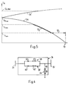
- the diode blocks 36 are preferably formed as shown in FIG. 4.
- Two diode elements 58, 58 ', each with a diode 60, 60' and series-connected resistor 62, 62 ', are connected in parallel between two adjacent sections 24'.
- the control rail 24 can be designed to produce the desired voltage levels in the distance Ud. If, on the other hand, the diode 60 goes defective, the diode 62 'takes over the function, the resistor 62' in question preferably being selected such that an error in this diode block 36 can be detected on the basis of the test voltage Up.
- the diode block 36 further points in the forward direction of the diode elements 58, 58 ', followed by a diode element 64 with a Zener diode 66 and one to it Series-connected further resistor 68, which is connected at the other end to the zero rail 26.
- a diode element 64 with a Zener diode 66 and one to it Series-connected further resistor 68, which is connected at the other end to the zero rail 26.
- the short circuit at 70 can be generated either by the rear scanner 32 of the preceding or stationary second vehicle 14 or by a short circuit between the control rail 24 and the zero rail 26.
- the drive control unit 40 regulates the speed of the drive device 16 in the range between Umax and Umin in the measured distance variable Ud in accordance with the speed control variable Us derived from the distance variable Ub (see FIG. 2), which is always slightly below the maximum permitted at the moment given by the distance variable Ud Speed lies.
- the speed control variable decreases Us at or below the voltage Umin, the vehicle 12 is stopped. It therefore always stops at least at a distance from the short circuit 70 indicated by the double arrow 72 in FIG. 5.
- the control rail 24 is designed such that this distance 72 always includes a plurality of sections 24 ′.
- the drive control unit 40 regulates the drive device 16 to a speed that corresponds to the predetermined maximum permissible speed. If the second vehicle 14 or short circuit 70 is very far away, the distance variable Ud corresponds to a value denoted by Udmax in FIG. 5, which is given by the voltage division of the open circuit voltage of the voltage source 44 by the load resistor 46 and the impedance of the chain conductor. If, on the other hand, the latter is interrupted, the voltage Ud increases compared to the value Udmax, as shown by the upper curve Ud 'in FIG. 5. The two control units 48, 48 '(see FIG. 3) initiate emergency braking as soon as the distance variable Ud exceeds a limit value which is shown as Ud open in FIG. 5.
- control device 18 With generally known switching arrangements in analog or digital technology. It goes without saying that in the case of a digital form of training, analog signals, such as the distance U, for example, are converted by means of analog-digital converters.
- analog signals such as the distance U, for example, are converted by means of analog-digital converters.
- the control device 18 can also be programmed accordingly Have microprocessors to perform the functions set out above. It is of course also conceivable to connect more than two control units in parallel and to compare the corresponding outputs by means of more than one comparator unit in order to further improve safety.
- control rail 24 it is also conceivable to design the control rail 24 as an uninterrupted resistance body with a resistance distributed uniformly over the length of the rail. It would also be conceivable to determine the distance and thus the distance between two successive vehicles 12, 14 using electromagnetic waves, microwaves, visible or infrared radiation or using sound or ultrasound waves.
- control rail 24 is short-circuited with the zero rail 26 each time a switch is switched at the open end of the track in question. This ensures that vehicles approaching the switch on this track stop at a distance 72 (FIG. 5) in front of the switch when the switch is not set to pass. Likewise, at the end of the web the Control rail 24 short-circuited with zero rail 26 in order to prevent vehicles 12, 14 from crossing the end of the path. It is also conceivable to leave the control rail 24 open at the switch, since this is also recognized by the control device 18.
- control rail 24 can be artificially extended so that vehicles approaching the web end come to a stop shortly before or at the end of the web.
- the diode blocks between two sections on both sides of the diode elements can have a diode element to the zero rail.
- the diode element connected downstream in the forward direction of the diode elements can in this case have a series connection of a diode, with the forward direction of the diode element against the neutral rail, and a Zener diode connected between this diode and the neutral rail with opposite polarity.
- the diode and zener diode are connected in series with the reverse direction of passage.
- a switchover device is provided on the vehicle in order to switch the positive pole of the voltage source to the control rail and the negative pole to the zero rail when driving in the forward direction of the diode elements, and vice versa when driving in the opposite direction.
- the switchover device also short-circuits the rear sliding shoes in the respective direction of travel and connects the respective front sliding shoes to the voltage source in the correct polarity.
Landscapes
- Engineering & Computer Science (AREA)
- Mechanical Engineering (AREA)
- Automation & Control Theory (AREA)
- Train Traffic Observation, Control, And Security (AREA)
- Electric Propulsion And Braking For Vehicles (AREA)
Applications Claiming Priority (2)
| Application Number | Priority Date | Filing Date | Title |
|---|---|---|---|
| CH3597/91A CH682738A5 (de) | 1991-12-06 | 1991-12-06 | Einrichtung zum sicheren automatischen Steuern des gegenseitigen Abstandes von Fahrzeugen. |
| CH3597/91 | 1991-12-06 |
Publications (2)
| Publication Number | Publication Date |
|---|---|
| EP0545026A1 true EP0545026A1 (fr) | 1993-06-09 |
| EP0545026B1 EP0545026B1 (fr) | 1995-07-26 |
Family
ID=4259419
Family Applications (1)
| Application Number | Title | Priority Date | Filing Date |
|---|---|---|---|
| EP92117051A Expired - Lifetime EP0545026B1 (fr) | 1991-12-06 | 1992-10-06 | Système de commande automatique sûre de la distance mutuelle de véhicules. |
Country Status (8)
| Country | Link |
|---|---|
| US (1) | US5388789A (fr) |
| EP (1) | EP0545026B1 (fr) |
| JP (1) | JPH0640337A (fr) |
| KR (1) | KR930012495A (fr) |
| AU (1) | AU657377B2 (fr) |
| CH (1) | CH682738A5 (fr) |
| DE (1) | DE59203031D1 (fr) |
| TW (1) | TW201351B (fr) |
Families Citing this family (11)
| Publication number | Priority date | Publication date | Assignee | Title |
|---|---|---|---|---|
| KR970010506A (ko) * | 1995-08-21 | 1997-03-27 | 이희종 | 열차의 자동속도 조정코드 발생 방법 |
| US5901650A (en) * | 1997-10-14 | 1999-05-11 | Honda Of America Mfg., Inc. | Dynamic buffer for conveyor modules |
| DE19828878A1 (de) * | 1998-06-23 | 1999-12-30 | Siemens Ag | Verfahren zur Datenreduktion im Bahnbetrieb |
| WO2007132951A1 (fr) * | 2006-05-11 | 2007-11-22 | Posco | Procédé et appareil de commande et de freinage d'urgence dans des systèmes de transport rapide personnalisé dotés de moteurs à induction linéaires |
| WO2008096048A1 (fr) * | 2007-02-07 | 2008-08-14 | Siemens Transportation Systems S.A.S. | Systeme de controle anticollision pour un vehicule |
| GB2463700A (en) * | 2008-09-23 | 2010-03-24 | Robin Weber | A signalling system to control the distance between two vehicles on the same track |
| KR101203714B1 (ko) * | 2009-10-07 | 2012-11-21 | 한국전자통신연구원 | 주행 안전 제공 시스템 및 방법 |
| FR2960651B1 (fr) * | 2010-05-28 | 2013-08-23 | Thales Sa | Procede de correction de mesures de reflectivite et radar mettant en oeuvre ce procede |
| CN102529962B (zh) * | 2010-12-08 | 2014-11-05 | 安尼株式会社 | 移动体防碰撞装置和移动体 |
| US11526176B2 (en) * | 2017-02-14 | 2022-12-13 | Volvo Truck Corporation | Sensing arrangement for determining a displacement of a vehicle with respect to an electrical road system |
| DE102020203237A1 (de) | 2020-03-13 | 2021-09-16 | Siemens Mobility GmbH | Verfahren und System zur Abstandsbestimmung für entlang einer Fahrstrecke fahrende Fahrzeuge |
Citations (6)
| Publication number | Priority date | Publication date | Assignee | Title |
|---|---|---|---|---|
| CH397761A (de) * | 1963-03-15 | 1965-08-31 | Honegger Charles | Einrichtung zur automatischen Steuerung des gegenseitigen Abstandes von Fahrzeugen |
| CH426923A (de) * | 1965-08-17 | 1966-12-31 | Honegger Charles | Einrichtung zur automatischen Steuerung des gegenseitigen Abstandes von Fahrzeugen |
| DE2215666A1 (de) * | 1972-03-27 | 1973-10-04 | Zehnel Paul Gerhard Dipl Ing | Verhuetung des unterschreitens festgelegter abstaende von hintereinander fahrenden wagen |
| CH554253A (de) * | 1973-07-11 | 1974-09-30 | Ourny Bernard | Installation de commande de la marche de vehicules circulant sur au moins une voie. |
| DE2948384A1 (de) * | 1979-12-01 | 1981-06-04 | Brown, Boveri & Cie Ag, 6800 Mannheim | Sicherheitssystem zur geschwindigkeitsregelung fuer schienengebundene fahrzeuge |
| US4956779A (en) * | 1988-11-22 | 1990-09-11 | General Signal Corporation | Digital overspeed controller for use in a vital processing system |
Family Cites Families (4)
| Publication number | Priority date | Publication date | Assignee | Title |
|---|---|---|---|---|
| DE1291765B (de) * | 1963-09-20 | 1969-04-03 | Licentia Gmbh | Einrichtung zur Ermittlung des Abstandes hintereinander fahrender schienengebundenerFahrzeuge, insbesondere fuer Unterpflasterbahnen |
| US3835950A (en) * | 1971-09-23 | 1974-09-17 | Mitsubishi Electric Corp | Apparatus for controlling the speed and spacing of vehicles |
| US3817344A (en) * | 1971-09-23 | 1974-06-18 | Mitsubishi Electric Corp | Apparatus for controlling vehicular speed and interspacing |
| GB1576357A (en) * | 1976-03-24 | 1980-10-08 | Bongiorno D | Railway system and vehicle for such a system |
-
1991
- 1991-12-06 CH CH3597/91A patent/CH682738A5/de not_active IP Right Cessation
-
1992
- 1992-10-06 EP EP92117051A patent/EP0545026B1/fr not_active Expired - Lifetime
- 1992-10-06 DE DE59203031T patent/DE59203031D1/de not_active Expired - Fee Related
- 1992-10-29 TW TW081108631A patent/TW201351B/zh active
- 1992-11-16 JP JP4329994A patent/JPH0640337A/ja active Pending
- 1992-11-23 KR KR1019920022105A patent/KR930012495A/ko not_active Withdrawn
- 1992-11-30 AU AU29761/92A patent/AU657377B2/en not_active Ceased
- 1992-12-04 US US07/985,482 patent/US5388789A/en not_active Expired - Fee Related
Patent Citations (6)
| Publication number | Priority date | Publication date | Assignee | Title |
|---|---|---|---|---|
| CH397761A (de) * | 1963-03-15 | 1965-08-31 | Honegger Charles | Einrichtung zur automatischen Steuerung des gegenseitigen Abstandes von Fahrzeugen |
| CH426923A (de) * | 1965-08-17 | 1966-12-31 | Honegger Charles | Einrichtung zur automatischen Steuerung des gegenseitigen Abstandes von Fahrzeugen |
| DE2215666A1 (de) * | 1972-03-27 | 1973-10-04 | Zehnel Paul Gerhard Dipl Ing | Verhuetung des unterschreitens festgelegter abstaende von hintereinander fahrenden wagen |
| CH554253A (de) * | 1973-07-11 | 1974-09-30 | Ourny Bernard | Installation de commande de la marche de vehicules circulant sur au moins une voie. |
| DE2948384A1 (de) * | 1979-12-01 | 1981-06-04 | Brown, Boveri & Cie Ag, 6800 Mannheim | Sicherheitssystem zur geschwindigkeitsregelung fuer schienengebundene fahrzeuge |
| US4956779A (en) * | 1988-11-22 | 1990-09-11 | General Signal Corporation | Digital overspeed controller for use in a vital processing system |
Also Published As
| Publication number | Publication date |
|---|---|
| TW201351B (fr) | 1993-03-01 |
| US5388789A (en) | 1995-02-14 |
| AU657377B2 (en) | 1995-03-09 |
| EP0545026B1 (fr) | 1995-07-26 |
| DE59203031D1 (de) | 1995-08-31 |
| JPH0640337A (ja) | 1994-02-15 |
| AU2976192A (en) | 1993-06-10 |
| CH682738A5 (de) | 1993-11-15 |
| KR930012495A (ko) | 1993-07-20 |
Similar Documents
| Publication | Publication Date | Title |
|---|---|---|
| DE4034537C2 (fr) | ||
| EP0545026B1 (fr) | Système de commande automatique sûre de la distance mutuelle de véhicules. | |
| DE102019112839B3 (de) | Schutz- und Überwachungseinrichtung in einer Ladeinfrastruktur zum Laden von elektrisch angetriebenen Fahrzeugen und Verfahren zur Überwachung einer Ladeinfrastruktur | |
| WO2020104454A1 (fr) | Procédé de surveillance fiable du fonctionnement d'un dispositif de transport électromagnétique | |
| WO2016030210A1 (fr) | Circuit électrique pour véhicule et procédé de prise de contact et/ou de cessation de contact entre un véhicule et un réseau électrique externe au véhicule | |
| DE2903809A1 (de) | Ueberwachungs- und anzeigeschaltung | |
| EP2559602B1 (fr) | Procédé et dispositif destiné à bloquer la traction d'un véhicule ferroviaire arrêté | |
| EP3631483A1 (fr) | Procédé et dispositif de localisation de défauts sur une ligne d'alimentation en énergie pour des systèmes à courant continu | |
| WO2004077177A1 (fr) | Procede et dispositif pour deconnecter de maniere sure des commandes electriques | |
| EP4417484A1 (fr) | Système de compteur d'essieux pour surveiller une section de voie d'un système de rails | |
| DE2704548C2 (de) | Sicherheitsanordnung für folgemäßig oder abschnittweise verkehrende, spurgeführte Fahrzeuge | |
| DE3048683A1 (de) | "verfahren und anordnung zur ueberwachung von stromwerten in einem mit hilfe von thyristoren gesteuerten gleichstromantrieb" | |
| DE3015955C2 (fr) | ||
| DE1449047A1 (de) | Selbstueberwachungsvorrichtung fuer Warnanlagen | |
| EP1892823B1 (fr) | Procédé destiné à la régulation d'un convertisseur de puissance côté réseau pour véhicules sur rail | |
| DE3519222C2 (fr) | ||
| DE2537781A1 (de) | Fahrzeugsignalsystem | |
| AT414116B (de) | Verfahren zum überwachen von zählpunkten und zählpunkt für gleisfreimeldeanlagen | |
| DE3638680C2 (fr) | ||
| DE948189C (de) | Annaeherungsschaltung fuer auf derselben Fahrbahn motorisch bewegte Geraete, wie Krane, Aufzuege od. dgl. | |
| DE2444251A1 (de) | Gleisstromkreis, insbesondere fuer gleichstrombahnen mit chopper-gesteuerten triebfahrzeugen | |
| DE2948384C2 (de) | Sicherheitseinrichtung zur Geschwindigkeitsregelung für schienengebundene Fahrzeuge | |
| DE19823348A1 (de) | Verfahren zur lastunabhängigen Beschleunigungsregelung bei einem elektrisch angetriebenen Fahrzeug | |
| DE2928809C2 (fr) | ||
| WO2024046725A1 (fr) | Procédé de surveillance d'une direction de déplacement spécifiée pour un véhicule ferroviaire |
Legal Events
| Date | Code | Title | Description |
|---|---|---|---|
| PUAI | Public reference made under article 153(3) epc to a published international application that has entered the european phase |
Free format text: ORIGINAL CODE: 0009012 |
|
| AK | Designated contracting states |
Kind code of ref document: A1 Designated state(s): DE FR GB IT |
|
| 17P | Request for examination filed |
Effective date: 19931202 |
|
| RAP1 | Party data changed (applicant data changed or rights of an application transferred) |
Owner name: AEG MONORAIL SYSTEMS, INC. |
|
| 17Q | First examination report despatched |
Effective date: 19940822 |
|
| GRAA | (expected) grant |
Free format text: ORIGINAL CODE: 0009210 |
|
| AK | Designated contracting states |
Kind code of ref document: B1 Designated state(s): DE FR GB IT |
|
| REF | Corresponds to: |
Ref document number: 59203031 Country of ref document: DE Date of ref document: 19950831 |
|
| GBT | Gb: translation of ep patent filed (gb section 77(6)(a)/1977) |
Effective date: 19950822 |
|
| ITF | It: translation for a ep patent filed | ||
| ET | Fr: translation filed | ||
| PLBE | No opposition filed within time limit |
Free format text: ORIGINAL CODE: 0009261 |
|
| 26N | No opposition filed | ||
| PGFP | Annual fee paid to national office [announced via postgrant information from national office to epo] |
Ref country code: DE Payment date: 19960920 Year of fee payment: 5 |
|
| PG25 | Lapsed in a contracting state [announced via postgrant information from national office to epo] |
Ref country code: DE Free format text: LAPSE BECAUSE OF NON-PAYMENT OF DUE FEES Effective date: 19980701 |
|
| PGFP | Annual fee paid to national office [announced via postgrant information from national office to epo] |
Ref country code: GB Payment date: 20011010 Year of fee payment: 10 Ref country code: FR Payment date: 20011010 Year of fee payment: 10 |
|
| REG | Reference to a national code |
Ref country code: GB Ref legal event code: IF02 |
|
| PG25 | Lapsed in a contracting state [announced via postgrant information from national office to epo] |
Ref country code: GB Free format text: LAPSE BECAUSE OF NON-PAYMENT OF DUE FEES Effective date: 20021006 |
|
| GBPC | Gb: european patent ceased through non-payment of renewal fee |
Effective date: 20021006 |
|
| PG25 | Lapsed in a contracting state [announced via postgrant information from national office to epo] |
Ref country code: FR Free format text: LAPSE BECAUSE OF NON-PAYMENT OF DUE FEES Effective date: 20030630 |
|
| REG | Reference to a national code |
Ref country code: FR Ref legal event code: ST |
|
| PG25 | Lapsed in a contracting state [announced via postgrant information from national office to epo] |
Ref country code: IT Free format text: LAPSE BECAUSE OF NON-PAYMENT OF DUE FEES;WARNING: LAPSES OF ITALIAN PATENTS WITH EFFECTIVE DATE BEFORE 2007 MAY HAVE OCCURRED AT ANY TIME BEFORE 2007. THE CORRECT EFFECTIVE DATE MAY BE DIFFERENT FROM THE ONE RECORDED. Effective date: 20051006 |