EP0545031A1 - Méthode de préparation de signaux de télévision sur proteuse et/ou de signaux et son utilisation correspondante - Google Patents
Méthode de préparation de signaux de télévision sur proteuse et/ou de signaux et son utilisation correspondante Download PDFInfo
- Publication number
- EP0545031A1 EP0545031A1 EP92117171A EP92117171A EP0545031A1 EP 0545031 A1 EP0545031 A1 EP 0545031A1 EP 92117171 A EP92117171 A EP 92117171A EP 92117171 A EP92117171 A EP 92117171A EP 0545031 A1 EP0545031 A1 EP 0545031A1
- Authority
- EP
- European Patent Office
- Prior art keywords
- signals
- frequency
- channel
- digital
- transmission
- Prior art date
- Legal status (The legal status is an assumption and is not a legal conclusion. Google has not performed a legal analysis and makes no representation as to the accuracy of the status listed.)
- Granted
Links
Images




Classifications
-
- H—ELECTRICITY
- H04—ELECTRIC COMMUNICATION TECHNIQUE
- H04N—PICTORIAL COMMUNICATION, e.g. TELEVISION
- H04N21/00—Selective content distribution, e.g. interactive television or video on demand [VOD]
- H04N21/20—Servers specifically adapted for the distribution of content, e.g. VOD servers; Operations thereof
- H04N21/23—Processing of content or additional data; Elementary server operations; Server middleware
- H04N21/238—Interfacing the downstream path of the transmission network, e.g. adapting the transmission rate of a video stream to network bandwidth; Processing of multiplex streams
- H04N21/2383—Channel coding or modulation of digital bit-stream, e.g. QPSK modulation
-
- H—ELECTRICITY
- H04—ELECTRIC COMMUNICATION TECHNIQUE
- H04J—MULTIPLEX COMMUNICATION
- H04J1/00—Frequency-division multiplex systems
- H04J1/02—Details
- H04J1/04—Frequency-transposition arrangements
-
- H—ELECTRICITY
- H04—ELECTRIC COMMUNICATION TECHNIQUE
- H04N—PICTORIAL COMMUNICATION, e.g. TELEVISION
- H04N21/00—Selective content distribution, e.g. interactive television or video on demand [VOD]
- H04N21/20—Servers specifically adapted for the distribution of content, e.g. VOD servers; Operations thereof
- H04N21/23—Processing of content or additional data; Elementary server operations; Server middleware
- H04N21/236—Assembling of a multiplex stream, e.g. transport stream, by combining a video stream with other content or additional data, e.g. inserting a URL [Uniform Resource Locator] into a video stream, multiplexing software data into a video stream; Remultiplexing of multiplex streams; Insertion of stuffing bits into the multiplex stream, e.g. to obtain a constant bit-rate; Assembling of a packetised elementary stream
- H04N21/2365—Multiplexing of several video streams
-
- H—ELECTRICITY
- H04—ELECTRIC COMMUNICATION TECHNIQUE
- H04N—PICTORIAL COMMUNICATION, e.g. TELEVISION
- H04N21/00—Selective content distribution, e.g. interactive television or video on demand [VOD]
- H04N21/40—Client devices specifically adapted for the reception of or interaction with content, e.g. set-top-box [STB]; Operations thereof
- H04N21/43—Processing of content or additional data, e.g. demultiplexing additional data from a digital video stream; Elementary client operations, e.g. monitoring of home network or synchronising decoder's clock; Client middleware
- H04N21/434—Disassembling of a multiplex stream, e.g. demultiplexing audio and video streams, extraction of additional data from a video stream; Remultiplexing of multiplex streams; Extraction or processing of SI; Disassembling of packetised elementary stream
- H04N21/4347—Demultiplexing of several video streams
-
- H—ELECTRICITY
- H04—ELECTRIC COMMUNICATION TECHNIQUE
- H04N—PICTORIAL COMMUNICATION, e.g. TELEVISION
- H04N21/00—Selective content distribution, e.g. interactive television or video on demand [VOD]
- H04N21/40—Client devices specifically adapted for the reception of or interaction with content, e.g. set-top-box [STB]; Operations thereof
- H04N21/43—Processing of content or additional data, e.g. demultiplexing additional data from a digital video stream; Elementary client operations, e.g. monitoring of home network or synchronising decoder's clock; Client middleware
- H04N21/438—Interfacing the downstream path of the transmission network originating from a server, e.g. retrieving encoded video stream packets from an IP network
- H04N21/4382—Demodulation or channel decoding, e.g. QPSK demodulation
-
- H—ELECTRICITY
- H04—ELECTRIC COMMUNICATION TECHNIQUE
- H04N—PICTORIAL COMMUNICATION, e.g. TELEVISION
- H04N7/00—Television systems
- H04N7/08—Systems for the simultaneous or sequential transmission of more than one television signal, e.g. additional information signals, the signals occupying wholly or partially the same frequency band, e.g. by time division
- H04N7/0806—Systems for the simultaneous or sequential transmission of more than one television signal, e.g. additional information signals, the signals occupying wholly or partially the same frequency band, e.g. by time division the signals being two or more video signals
-
- H—ELECTRICITY
- H04—ELECTRIC COMMUNICATION TECHNIQUE
- H04N—PICTORIAL COMMUNICATION, e.g. TELEVISION
- H04N7/00—Television systems
- H04N7/24—Systems for the transmission of television signals using pulse code modulation
- H04N7/52—Systems for transmission of a pulse code modulated video signal with one or more other pulse code modulated signals, e.g. an audio signal or a synchronizing signal
- H04N7/54—Systems for transmission of a pulse code modulated video signal with one or more other pulse code modulated signals, e.g. an audio signal or a synchronizing signal the signals being synchronous
Definitions
- the invention is based on a method according to the preamble of claim 1. Such a method is known from DE 40 08 201 A1.
- television signals to be processed are digitized individually by means of A / D converters and each digitally converted into different frequency ranges, the conversion being carried out in such a way that at least the useful signal components do not overlap in frequency.
- the television signals thus converted are then combined by digital addition to form a frequency division multiplex signal which is transmitted.
- the frequency division multiplex signal is preferably converted back with only one D / A converter.
- the object of the invention is to enable high-quality signal transmission with little effort. This object is achieved by the steps of claim 1.
- the further claims show further developments or an application of the method.
- the invention is based on the following findings: Due to the measures according to the invention, the signals do not have to be demodulated before transmission, for example in CVBS and audio signals, YUV and audio signals or component signals (for example MAC signals), and modulated again after transmission will. A loss of quality that inevitably occurs with analog modulation / demodulation is avoided. After the transmission, the signals can be prepared in a simple manner and without great loss of quality in a compatible manner for existing feeder and / or distribution networks, so that existing analog or digital transmission and / or distribution devices, for example existing KTV networks, can continue to be used.
- the embodiment according to claim 2 has the advantage that, in particular when fewer subscribers are supplied, existing transmission facilities can be used without additional effort. This configuration is also flexible with regard to further processing of the signals.
- the embodiment according to claim 3 allows an inexpensive and high quality signal distribution over fiber optic networks, in particular also local networks. Since the signals are available in high quality at the fiber optic end points, the effort at the receiving end can be considerably reduced. Individual conversions in the analog range are not required. The D / A conversion at the receiving end can be carried out for several channels with only one D / A converter.
- the signal processing according to the invention is also suitable for any television standards, in particular also for the frequency grid of the MAC or HDMAC signals.
- the special one The advantage of the solution according to the invention is that it can be used in the entire broadband distribution network, ie from the feed source to the main transfer point (HÜP) at the subscriber, without the concept of signal processing and the system components having to be changed.
- FIG. 1 The individual process steps of signal processing are shown in FIG. 1 using the example of an 8-channel transmission system in a 7 MHz grid.
- the television channels themselves Usually in residual sideband-modulated form with two modulated sound carriers in the HF position (1), are converted into the standard IF range from 32.85 - 39.85 MHz (2) and with a sampling frequency of 28 MHz using an A / D -Digital converter (3).
- This process is shown in FIG. 1 as an example for TV channel 5 (lower special channel area) and TV channel 14 (upper special channel area).
- the signal form of the TV signal is not changed and is digitized in a closed form (residual sideband modulation).
- a "digital IF signal” is thus present at the output of each A / D converter (3).
- a further step (processing of the closed digitized signals in the baseband position) now takes place for the preparation for transmission, which is not shown in FIG. 1 and is only explained in more detail in connection with FIG. 2.
- the subsequent digital frequency conversion by means of the modules DFU digitally converts the signals channel by channel into different frequency ranges, the conversion being carried out in such a way that at least the useful signal components do not overlap in frequency.
- the procedure is such that each channel signal is converted into a different, but freely selectable 7 MHz frequency slot of the frequency band (4) which is present at the output of the digital frequency converter, consisting of the 8 individual converters DFU.
- the 8 channel signals are then combined by digital addition, symbolized by the unit ⁇ , to form an 8-channel digital frequency division multiplex signal.
- the bandwidth at the adder output is then 56 MHz (8x7 MHz).
- this band is then transmitted to the reception side at an bit rate of 1,344 Mbit / s (including the synchronization) by an optical transmission system.
- an optical transmission system In a system with a transmission bit rate of approx. 2.7 Gbit / s, up to 16 TV programs can be viewed be transmitted.
- On the receiver side apart from the optical receiving unit, there is preferably only a D / A converter for the entire frequency division multiplex signal, which converts this frequency division multiplex signal back, and a broadband HF converter KGU, which converts the channel group of 8 TV channels into the desired and desired for the subscriber implement reception-compatible VHF / UHF range (6).
- This signal processing according to FIG. 1 also forms the basis of the method according to DE 40 08 201 A1.
- the "digital intermediate frequency" interface is separated according to the invention (FIG. 2) and the digital intermediate frequency signals are additionally converted into the frequency range 0-7 MHz, that is to say in the baseband position.
- the baseband position here means a residual sideband-modulated television signal with image carrier and accompanying sound, which was implemented in the frequency range as close to frequency 0 as possible.
- FIG. 3 shows the spectra for a single channel before and after the conversion into this baseband position.
- the generalized Nyquist theorem which relates to the bandwidth of the sampled signal, is therefore not violated.
- BKVLNz broadband communication connection network
- the system components in the network can be distributed so that both a signal supply via the BK connection line network to the higher-level BK amplifier point üKVrSt as well as a distribution from the user-side amplifier point bBKVrSt over the BK connection network BKAsB to the main transfer point HÜP is possible.
- Such signal processing can also be located at the source.
- the digital frequency converters DFU1 ... DFUn then convert the signals, as already described in connection with FIG. 1, into the frequency slot desired for distribution.
- the digital IF signals can either be multiplexed into a 139.264 Mbit / s frame of the plesiochronous digital hierarchy or mapped into an STM1 frame of the synchronous hierarchy and in transmission facilities of the BK connection line network BKVLNz or the telecommunications network (broadband distribution network, directional radio, fiber optic network) ) can be fed.
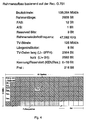
- FIG. 4 shows a possible frame structure for TV transmission according to CCITT recommendation G.751.
- the 2928 bits of the frame are arranged byte by byte in 61 columns and 6 rows. Because of the 9-bit structure of the TV signal and the 8-bit structure of the frame, there are two different frame configurations.
- the TV signal occupied 333 bytes in the first frame and 324 bytes in the second frame. With the help of the length indicator LI, the current occupancy of the frame can be determined on the receiving side.
- the signals KEN / Res. are used to synchronize the TV signals that may be transmitted in two different ways.
- FIG. 5 shows in a block diagram the modules for a single TV channel transmission with a bit rate of 139.264 Mbit / s.
- the output signal of the digital frequency converter DFU with the bit rate of 126 Mbit / s is fed to the multiplexer via a buffer memory FIFO.
- the fill level of the buffer tank determines which frame configuration must be selected for the transmission.
- the transmission clock for the multiplexer is derived from an isochronous clock (eg T3 on). Since the sampling frequency of 28 MHz for the A / D converter is also derived from this clock, the usual stuffing methods can be dispensed with.
- the frame synchronization at the receiving end can be carried out according to the known methods.
- the data are read into the buffer memory FIFO 'by the demultiplexer and converted by the digital frequency converter DFU' at a clock rate of 112 MHz from the baseband position to the digital IF range.
- DFU' digital frequency converter
- all channels are each converted into this same digital intermediate frequency position.
- a digital single-channel further processing can take place from this digital intermediate frequency position.
- a D / A converter at a clock rate of 112 MHz can subsequently be used to convert it into a standard IF position (32.85 - 39.85 MHz), so that analog processing, e.g. B. over existing networks, is possible.
- the digital baseband signals can be converted into different frequency slots of the frequency band from 0 ... 56 MHz by means of various digital frequency converters DFU1 ... DFUn to form a frequency division multiplex signal (cf. FIGS. 1 and 2) (cf. FIG. 1, line 4 ) and then fed into a distribution network.
- the D / A converters are then located at the main transfer points HÜP of the participants, where a frequency conversion of all channels in groups then takes place with only one frequency converter U (FIG. 2).
- the participants then each receive a channel group in the RF position ( Figure 1, line 6).
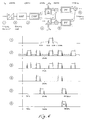
- FIG. 6 shows the principle of the one used according to the invention digital frequency conversion for a single channel using a block diagram and the signal spectra.
- the implementation in baseband is not considered here.
- the digital frequency conversion has the task of preparing the closed coded individual channels by digital mixing and filtering in such a way that they can then be combined into a frequency multiplex signal by digital addition. Further details on such a digital frequency conversion can also be found in German patent applications P 40 41 634.8 and P 40 26 477.7.
- the anti-alias filter AAF and the single sideband filter ESBF are identical for all TV channels.
- the carrier samples of the digital mixer DM and the coefficients of the interpolation filter IPF differ from channel to channel.
- the use of complex filtering and polyphase filtering in the interpolation filter leads on the one hand to a considerable reduction in the filtering effort and on the other hand to a consistently low clock frequency of 28 MHz for the entire processing unit.
- the tasks of the individual function blocks are evident from the spectra in FIG. 6.
- the remaining interference components of the adjacent channels are first suppressed to at least 60 dB with an anti-alias filter AAF (3).
- the single sideband filter ESBF filters out the lower sidebands and their frequency multiples (4).
- the frequency responses of these filters ESBF and IPF are shown in FIG. Because of the increased bandgap due to the single-sideband filter ESBF, the filter effort with the interpolation filter IPF can be significantly reduced.
- the digital mixer DM moves the signal into the target range (5).
- the target range the frequency band 49 - 56 MHz selected.
- the interpolation filter IPF suppresses the repetition spectrum (6) falling in the useful frequency range - depending on the desired channel number, it is the upper or the lower signal spectrum that is suppressed - so that in the following adder unit several channels prepared in the same way in the band from 0 - 56 MHz can be summarized.
Landscapes
- Engineering & Computer Science (AREA)
- Signal Processing (AREA)
- Multimedia (AREA)
- Physics & Mathematics (AREA)
- Electromagnetism (AREA)
- Computer Networks & Wireless Communication (AREA)
- Two-Way Televisions, Distribution Of Moving Picture Or The Like (AREA)
- Television Systems (AREA)
- Preparation Of Compounds By Using Micro-Organisms (AREA)
- Saccharide Compounds (AREA)
- Time-Division Multiplex Systems (AREA)
Applications Claiming Priority (2)
| Application Number | Priority Date | Filing Date | Title |
|---|---|---|---|
| DE4136111A DE4136111A1 (de) | 1991-11-02 | 1991-11-02 | Verfahren zur aufbereitung von getraegerten fernsehsignalen und/oder tonsignalen sowie anwendung |
| DE4136111 | 1991-11-02 |
Publications (2)
| Publication Number | Publication Date |
|---|---|
| EP0545031A1 true EP0545031A1 (fr) | 1993-06-09 |
| EP0545031B1 EP0545031B1 (fr) | 1996-09-18 |
Family
ID=6443940
Family Applications (1)
| Application Number | Title | Priority Date | Filing Date |
|---|---|---|---|
| EP92117171A Expired - Lifetime EP0545031B1 (fr) | 1991-11-02 | 1992-10-08 | Méthode de préparation de signaux de télévision sur proteuse et/ou de signaux et son utilisation correspondante |
Country Status (4)
| Country | Link |
|---|---|
| EP (1) | EP0545031B1 (fr) |
| AT (1) | ATE143206T1 (fr) |
| DE (2) | DE4136111A1 (fr) |
| ES (1) | ES2091989T3 (fr) |
Families Citing this family (3)
| Publication number | Priority date | Publication date | Assignee | Title |
|---|---|---|---|---|
| DE4428606B4 (de) * | 1994-08-12 | 2004-04-29 | Deutsche Telekom Ag | Verfahren und Anordnung zur Rundfunk-Übertragung von codierten Signalen |
| DE19703079A1 (de) * | 1997-01-29 | 1998-07-30 | Bosch Gmbh Robert | Verfahren zur Aufbereitung von in einer Zwischenfrequenzlage angelieferten Bandpaßsignalen |
| DE19804425A1 (de) * | 1998-02-05 | 1999-08-12 | Cit Alcatel | Breitbandinformationssystem für Verteildienste und interaktive Dienste |
Citations (3)
| Publication number | Priority date | Publication date | Assignee | Title |
|---|---|---|---|---|
| DE3707243A1 (de) * | 1987-03-06 | 1988-09-15 | Siemens Ag | Verfahren zur digitalen uebertragung von fernsehsignalen |
| EP0324954A2 (fr) * | 1988-01-16 | 1989-07-26 | Robert Bosch Gmbh | Procédé et dispositif pour la transmission en partage de signaux numérisés de télévision, de son et de données |
| DE4008201A1 (de) * | 1990-03-15 | 1991-09-26 | Ant Nachrichtentech | Verfahren zur aufbereitung von mehreren fernsehsignalen fuer uebertragungszwecke sowie anwendung |
-
1991
- 1991-11-02 DE DE4136111A patent/DE4136111A1/de not_active Ceased
-
1992
- 1992-10-08 EP EP92117171A patent/EP0545031B1/fr not_active Expired - Lifetime
- 1992-10-08 DE DE59207178T patent/DE59207178D1/de not_active Expired - Fee Related
- 1992-10-08 AT AT92117171T patent/ATE143206T1/de not_active IP Right Cessation
- 1992-10-08 ES ES92117171T patent/ES2091989T3/es not_active Expired - Lifetime
Patent Citations (3)
| Publication number | Priority date | Publication date | Assignee | Title |
|---|---|---|---|---|
| DE3707243A1 (de) * | 1987-03-06 | 1988-09-15 | Siemens Ag | Verfahren zur digitalen uebertragung von fernsehsignalen |
| EP0324954A2 (fr) * | 1988-01-16 | 1989-07-26 | Robert Bosch Gmbh | Procédé et dispositif pour la transmission en partage de signaux numérisés de télévision, de son et de données |
| DE4008201A1 (de) * | 1990-03-15 | 1991-09-26 | Ant Nachrichtentech | Verfahren zur aufbereitung von mehreren fernsehsignalen fuer uebertragungszwecke sowie anwendung |
Also Published As
| Publication number | Publication date |
|---|---|
| DE4136111A1 (de) | 1993-05-06 |
| ES2091989T3 (es) | 1996-11-16 |
| DE59207178D1 (de) | 1996-10-24 |
| ATE143206T1 (de) | 1996-10-15 |
| EP0545031B1 (fr) | 1996-09-18 |
Similar Documents
| Publication | Publication Date | Title |
|---|---|---|
| DE69027537T2 (de) | System zur synchronisierung von haupt- und hilfsvideosignalen | |
| EP0527289B1 (fr) | Procédé pour la transmission de signaux TVHD numériques | |
| DE3520209C2 (de) | Fernsehübertragungssystem | |
| DE19643872A1 (de) | Optische Netzabschlußeinheit eines hybriden Glasfaser-Koaxialkabel-Zugangsnetzes | |
| AT393582B (de) | Fernsehuebertragungssystem | |
| EP0545031B1 (fr) | Méthode de préparation de signaux de télévision sur proteuse et/ou de signaux et son utilisation correspondante | |
| DE69113625T2 (de) | Kompression digitaler videosignale. | |
| EP0114693B1 (fr) | Système de transmission d'un signal vidéo en couleur à haute définition | |
| EP0446612B1 (fr) | Procédé pour la préparation de plusieurs signaux de télévision pour des objets et applications de transmission | |
| EP0545030B1 (fr) | Méthode de préparation de signaux de sources d'image avec ou sans signaux de son et utilisation correspondante | |
| EP0706292A1 (fr) | Circuit pour commander la transmission d'information de services interactifs | |
| EP0226802B1 (fr) | Système de transmission d'informations de télévision | |
| DE3707243C2 (fr) | ||
| EP0012979B1 (fr) | Méthode pour la transmission de plusieurs signaux par une connexion à guide d'ondes de lumière, notamment entre un central et une jonction d'abonné | |
| EP0710024A2 (fr) | Réseau domestique pour la connexion d'abonnés à un réseau de distribution public pour signaux vidéo et/ou audio | |
| EP0063639A2 (fr) | Système de communication numérique à bande large | |
| EP0324954A2 (fr) | Procédé et dispositif pour la transmission en partage de signaux numérisés de télévision, de son et de données | |
| EP0446613B1 (fr) | Procédé de traitement de plusieurs signaux de télévision en vue de leur transmission et dispositif | |
| DE4433793C1 (de) | Verfahren zur Übertragung teilnehmerindividueller Dienste und Verteildienste | |
| DE69614072T2 (de) | Kabelnetzwerksystem für Videoverteilung und bidirektionale Datenübertragung, mit Freqenzumsetzung im Rückkanal | |
| DE3935183C2 (de) | Kabelfernseh-Übertragungssystem | |
| DE19632036A1 (de) | Verfahren und Aufbereitung von Abtastwerten | |
| DE3237790C2 (fr) | ||
| EP0645908A2 (fr) | Procédé de multiplexage par partage du temps | |
| DE4328487C2 (de) | Verfahren und Schaltungsanordnung zum Übertragen von Datenströmen über Zweidraht-Basisteilnehmeranschlußleitungen |
Legal Events
| Date | Code | Title | Description |
|---|---|---|---|
| PUAI | Public reference made under article 153(3) epc to a published international application that has entered the european phase |
Free format text: ORIGINAL CODE: 0009012 |
|
| 17P | Request for examination filed |
Effective date: 19930408 |
|
| AK | Designated contracting states |
Kind code of ref document: A1 Designated state(s): AT BE CH DE ES FR GB IE IT LI NL SE |
|
| 17Q | First examination report despatched |
Effective date: 19950407 |
|
| GRAG | Despatch of communication of intention to grant |
Free format text: ORIGINAL CODE: EPIDOS AGRA |
|
| GRAH | Despatch of communication of intention to grant a patent |
Free format text: ORIGINAL CODE: EPIDOS IGRA |
|
| RAP1 | Party data changed (applicant data changed or rights of an application transferred) |
Owner name: ROBERT BOSCH GMBH |
|
| GRAH | Despatch of communication of intention to grant a patent |
Free format text: ORIGINAL CODE: EPIDOS IGRA |
|
| GRAA | (expected) grant |
Free format text: ORIGINAL CODE: 0009210 |
|
| AK | Designated contracting states |
Kind code of ref document: B1 Designated state(s): AT BE CH DE ES FR GB IE IT LI NL SE |
|
| REF | Corresponds to: |
Ref document number: 143206 Country of ref document: AT Date of ref document: 19961015 Kind code of ref document: T |
|
| REG | Reference to a national code |
Ref country code: CH Ref legal event code: NV Representative=s name: SCINTILLA AG, DIREKTION |
|
| REF | Corresponds to: |
Ref document number: 59207178 Country of ref document: DE Date of ref document: 19961024 |
|
| REG | Reference to a national code |
Ref country code: IE Ref legal event code: FG4D Free format text: 69874 |
|
| REG | Reference to a national code |
Ref country code: ES Ref legal event code: FG2A Ref document number: 2091989 Country of ref document: ES Kind code of ref document: T3 |
|
| ITF | It: translation for a ep patent filed | ||
| GBT | Gb: translation of ep patent filed (gb section 77(6)(a)/1977) |
Effective date: 19961122 |
|
| ET | Fr: translation filed |
Free format text: CORRECTIONS |
|
| PLBE | No opposition filed within time limit |
Free format text: ORIGINAL CODE: 0009261 |
|
| 26N | No opposition filed | ||
| PGFP | Annual fee paid to national office [announced via postgrant information from national office to epo] |
Ref country code: GB Payment date: 20000927 Year of fee payment: 9 |
|
| PGFP | Annual fee paid to national office [announced via postgrant information from national office to epo] |
Ref country code: SE Payment date: 20001009 Year of fee payment: 9 |
|
| PGFP | Annual fee paid to national office [announced via postgrant information from national office to epo] |
Ref country code: FR Payment date: 20001010 Year of fee payment: 9 |
|
| PGFP | Annual fee paid to national office [announced via postgrant information from national office to epo] |
Ref country code: CH Payment date: 20001011 Year of fee payment: 9 Ref country code: AT Payment date: 20001011 Year of fee payment: 9 |
|
| PGFP | Annual fee paid to national office [announced via postgrant information from national office to epo] |
Ref country code: NL Payment date: 20001026 Year of fee payment: 9 |
|
| PGFP | Annual fee paid to national office [announced via postgrant information from national office to epo] |
Ref country code: IE Payment date: 20001027 Year of fee payment: 9 |
|
| PGFP | Annual fee paid to national office [announced via postgrant information from national office to epo] |
Ref country code: ES Payment date: 20001030 Year of fee payment: 9 |
|
| PGFP | Annual fee paid to national office [announced via postgrant information from national office to epo] |
Ref country code: BE Payment date: 20001214 Year of fee payment: 9 |
|
| PG25 | Lapsed in a contracting state [announced via postgrant information from national office to epo] |
Ref country code: IE Free format text: LAPSE BECAUSE OF FAILURE TO SUBMIT A TRANSLATION OF THE DESCRIPTION OR TO PAY THE FEE WITHIN THE PRESCRIBED TIME-LIMIT Effective date: 20011008 Ref country code: GB Free format text: LAPSE BECAUSE OF NON-PAYMENT OF DUE FEES Effective date: 20011008 Ref country code: AT Free format text: LAPSE BECAUSE OF NON-PAYMENT OF DUE FEES Effective date: 20011008 |
|
| PG25 | Lapsed in a contracting state [announced via postgrant information from national office to epo] |
Ref country code: SE Free format text: LAPSE BECAUSE OF NON-PAYMENT OF DUE FEES Effective date: 20011009 Ref country code: ES Free format text: LAPSE BECAUSE OF NON-PAYMENT OF DUE FEES Effective date: 20011009 |
|
| PGFP | Annual fee paid to national office [announced via postgrant information from national office to epo] |
Ref country code: DE Payment date: 20011022 Year of fee payment: 10 |
|
| PG25 | Lapsed in a contracting state [announced via postgrant information from national office to epo] |
Ref country code: LI Free format text: LAPSE BECAUSE OF NON-PAYMENT OF DUE FEES Effective date: 20011031 Ref country code: CH Free format text: LAPSE BECAUSE OF NON-PAYMENT OF DUE FEES Effective date: 20011031 Ref country code: BE Free format text: LAPSE BECAUSE OF NON-PAYMENT OF DUE FEES Effective date: 20011031 |
|
| REG | Reference to a national code |
Ref country code: GB Ref legal event code: IF02 |
|
| BERE | Be: lapsed |
Owner name: ROBERT BOSCH G.M.B.H. Effective date: 20011031 |
|
| PG25 | Lapsed in a contracting state [announced via postgrant information from national office to epo] |
Ref country code: NL Free format text: LAPSE BECAUSE OF NON-PAYMENT OF DUE FEES Effective date: 20020501 |
|
| GBPC | Gb: european patent ceased through non-payment of renewal fee |
Effective date: 20011008 |
|
| EUG | Se: european patent has lapsed |
Ref document number: 92117171.6 |
|
| REG | Reference to a national code |
Ref country code: CH Ref legal event code: PL |
|
| PG25 | Lapsed in a contracting state [announced via postgrant information from national office to epo] |
Ref country code: FR Free format text: LAPSE BECAUSE OF NON-PAYMENT OF DUE FEES Effective date: 20020628 |
|
| NLV4 | Nl: lapsed or anulled due to non-payment of the annual fee |
Effective date: 20020501 |
|
| REG | Reference to a national code |
Ref country code: IE Ref legal event code: MM4A |
|
| REG | Reference to a national code |
Ref country code: FR Ref legal event code: ST |
|
| PG25 | Lapsed in a contracting state [announced via postgrant information from national office to epo] |
Ref country code: DE Free format text: LAPSE BECAUSE OF NON-PAYMENT OF DUE FEES Effective date: 20030501 |
|
| REG | Reference to a national code |
Ref country code: ES Ref legal event code: FD2A Effective date: 20021113 |
|
| PG25 | Lapsed in a contracting state [announced via postgrant information from national office to epo] |
Ref country code: IT Free format text: LAPSE BECAUSE OF NON-PAYMENT OF DUE FEES Effective date: 20051008 |