EP0545100A1 - Vorrichtung zum Biegen von Trapezblechen - Google Patents
Vorrichtung zum Biegen von Trapezblechen Download PDFInfo
- Publication number
- EP0545100A1 EP0545100A1 EP92119106A EP92119106A EP0545100A1 EP 0545100 A1 EP0545100 A1 EP 0545100A1 EP 92119106 A EP92119106 A EP 92119106A EP 92119106 A EP92119106 A EP 92119106A EP 0545100 A1 EP0545100 A1 EP 0545100A1
- Authority
- EP
- European Patent Office
- Prior art keywords
- trapezoidal
- deformation space
- bending
- profile
- forming rollers
- Prior art date
- Legal status (The legal status is an assumption and is not a legal conclusion. Google has not performed a legal analysis and makes no representation as to the accuracy of the status listed.)
- Granted
Links
- 238000005452 bending Methods 0.000 title claims abstract description 13
- 239000007769 metal material Substances 0.000 claims abstract description 6
- 229910000838 Al alloy Inorganic materials 0.000 claims abstract description 3
- 229910052782 aluminium Inorganic materials 0.000 claims abstract description 3
- XAGFODPZIPBFFR-UHFFFAOYSA-N aluminium Chemical compound [Al] XAGFODPZIPBFFR-UHFFFAOYSA-N 0.000 claims abstract description 3
- 238000007493 shaping process Methods 0.000 claims description 3
- 230000035515 penetration Effects 0.000 claims description 2
- 239000004411 aluminium Substances 0.000 abstract 1
- 238000000034 method Methods 0.000 description 5
- 229910052751 metal Inorganic materials 0.000 description 3
- 239000002184 metal Substances 0.000 description 3
- 238000010276 construction Methods 0.000 description 2
- 239000000463 material Substances 0.000 description 2
- 238000003825 pressing Methods 0.000 description 2
- 239000011324 bead Substances 0.000 description 1
- 238000005516 engineering process Methods 0.000 description 1
- 238000004519 manufacturing process Methods 0.000 description 1
Images


Classifications
-
- B—PERFORMING OPERATIONS; TRANSPORTING
- B21—MECHANICAL METAL-WORKING WITHOUT ESSENTIALLY REMOVING MATERIAL; PUNCHING METAL
- B21D—WORKING OR PROCESSING OF SHEET METAL OR METAL TUBES, RODS OR PROFILES WITHOUT ESSENTIALLY REMOVING MATERIAL; PUNCHING METAL
- B21D11/00—Bending not restricted to forms of material mentioned in only one of groups B21D5/00, B21D7/00, B21D9/00; Bending not provided for in groups B21D5/00 - B21D9/00; Twisting
- B21D11/08—Bending by altering the thickness of part of the cross-section of the work
-
- B—PERFORMING OPERATIONS; TRANSPORTING
- B21—MECHANICAL METAL-WORKING WITHOUT ESSENTIALLY REMOVING MATERIAL; PUNCHING METAL
- B21D—WORKING OR PROCESSING OF SHEET METAL OR METAL TUBES, RODS OR PROFILES WITHOUT ESSENTIALLY REMOVING MATERIAL; PUNCHING METAL
- B21D11/00—Bending not restricted to forms of material mentioned in only one of groups B21D5/00, B21D7/00, B21D9/00; Bending not provided for in groups B21D5/00 - B21D9/00; Twisting
- B21D11/20—Bending sheet metal, not otherwise provided for
- B21D11/206—Curving corrugated sheets
-
- B—PERFORMING OPERATIONS; TRANSPORTING
- B21—MECHANICAL METAL-WORKING WITHOUT ESSENTIALLY REMOVING MATERIAL; PUNCHING METAL
- B21D—WORKING OR PROCESSING OF SHEET METAL OR METAL TUBES, RODS OR PROFILES WITHOUT ESSENTIALLY REMOVING MATERIAL; PUNCHING METAL
- B21D13/00—Corrugating sheet metal, rods or profiles; Bending sheet metal, rods or profiles into wave form
- B21D13/04—Corrugating sheet metal, rods or profiles; Bending sheet metal, rods or profiles into wave form by rolling
Definitions
- the invention relates to a device for bending trapezoidal or corrugated shaped profiled sheets made of metallic materials, preferably made of aluminum or aluminum alloys, wherein the bending radius lies in one plane with the longitudinal axis of the profiled sheet, consisting of an upper and lower forming roll, which in the base of the Trapezoidal surface can be pressed.
- a device of the type mentioned is known from DE 30 37 590 A1.
- a so-called buckling device engages in the profile chamber of a sheet metal profile, which consists of at least two shaped pieces which can be moved in the horizontal and vertical directions and can be pressed against the side walls of the sheet metal profile. This makes it possible to bend the side surfaces of the sheet metal profile uniformly in any shape, in particular for profile heights of more than 45 mm.
- the fittings consist of scissor-like crossed bag arms, the scissor movement being controlled as a function of the bending angle of the corrugated or profiled sheets.
- the teeth 4, 5 on the shaping rollers mesh with one another in such a way that the trapezoidal sheet which is passed between them is deformed in a flat sinusoidal curve.
- the depth of penetration of the rollers 6, 10 into the metallic material should be limited by a corresponding design of the shaped surfaces 2, 3.
- a preferred embodiment of the deformation space 14 between the two rollers 6, 10 has a concave cross section.
- the deformed trapezoidal sheet is placed between the rollers 6, 10 in such a way that it describes a gentle curve in all directions and maintains its trapezoidal shape even after the bending process.
- Fig. 2 the two intermeshing rollers 6, 10 are shown in a basic arrangement.
- the profile panel 1 is shown cut in its longitudinal direction.
- the gathering of the material in the deformed sheet plane results in an automatic curvature of the profiled sheet around the axis of the roller 10.
- Fig. 3 shows once again on an enlarged scale the deformation of the trapezoidal profile.
- the toothed roller 6 penetrates into the deformation space 14 and, upon further rotation, causes the trapezoidal sheet 1 to be deformed.
- the upper roller bodies 10 have teeth 12, 13 which correspond to the teeth of the lower roller.
- the cross section of the deformation space 14 has the shape of a concave lens. This means that the depression H between the trapezoidal sheet 1 and the roller body 6 is greatest in the middle, so that here the deformation of the profiled sheet is the least.
- the meshing rollers 6, 10 are shown in an enlarged view. It is important that the depth of deformation V does not exceed a certain level.
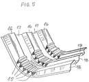
- the curved trapezoidal profile is shown in perspective.
- the beads 15 formed with the gears are molded into the roof plane 16 of the trapezoidal profile.
- the foot plane 17 remains undeformed, while the side surfaces 18 of the trapezoidal profile have slight deformations 19.
Landscapes
- Engineering & Computer Science (AREA)
- Mechanical Engineering (AREA)
- Bending Of Plates, Rods, And Pipes (AREA)
- Basic Packing Technique (AREA)
- Shaping Of Tube Ends By Bending Or Straightening (AREA)
Abstract
Description
- Die Erfindung betrifft eine Vorrichtung zum Biegen von trapez- oder wellförmig geformten Profiltafeln aus metallischen Werkstoffen, vorzugsweise aus Aluminium oder Aluminiumlegierungen, wobei der Biegeradius in einer Ebene mit der Längsachse der Profiltafel liegt, bestehend aus einer oberen und unteren Formwalze, die in die Basis der Trapezfläche eindrückbar sind.
- Eine Vorrichtung der eingangs genannten Art ist aus der DE 30 37 590 A1 bekannt. Bei dieser Vorrichtung greift in die Profilkammer eines Blechprofils eine sogenannte Beulvorrichtung ein, die aus mindestens zwei in horizontaler und vertikaler Richtung beweglichen Formstücken besteht, die gegen die Seitenwände des Blechprofils anpreßbar sind. Damit ist es möglich, die Seitenflächen des Blechprofils gleichmäßig in beliebiger Form, insbesondere bei Profilhöhen von mehr als 45 mm zu biegen.
- Gem. einem Ausführungsbeispiel der bekannten Vorrichtung bestehen die Formstücke aus scherenartig überkreuzten Beutelarmen, wobei die Scherenbewegung in Abhängigkeit vom Biegewinkel der gewellten oder profilierten Bleche gesteuert wird. Eine derartige Vorrichtung ist für viele Anwendungsfälle, wie z.B. auf der Baustelle, zu kompliziert und daher schlecht handhabbar.
- Aus der DE 21 61 457 A1 ist ferner ein Verfahren zum Biegen eines gewellten oder gerippten Bogens um eine zu der Riffelung rechtwinkligen Achse bekannt, wobei in die Riffelung mehrere in Bezug auf die Achse des Bogens herausragende Rippen gepreßt werden. Dieser Preßvorgang ist zwar mit einfachen Werkzeugen auszuführen, die aber aufgrund der aufzuwendenden Preßkräfte von erheblichem Gewicht sind. Eine Anwendung dieses Verfahrens vor Ort auf der Baustelle ist daher ebenfalls nicht möglich.
- Aufgabe der vorliegenden Erfindung ist es daher, bei einer Vorrichtung der eingangs genannten Art die beschriebenen Nachteile zu vermeiden und Profiltafeln in einer einfachen, transportablen und wenig anfälligen Vorrichtung in einem zum Priofilquerschnitt rechtswinkligen Bogen zu verformen.
- Diese Aufgabe wird erfindungsgemäß durch die in den Patentansprüchen angegebenen Merkmale gelöst. Es hat sich gezeigt, daß bei Verwendung von mit Zahnrädern 4, 5 ausgerüsteten Walzen 6, 10 eine konstruktiv einfache und fertigungstechnisch wenig anfällige Vorrichtung ermöglicht wird.
- Es ist besonders vorteilhaft, wenn die auf den Formwalzen angebrachten Zähne 4, 5 derart miteinander kämmen, daß das zwischen ihnen hindurchgeführte Trapezblech in einem flachen Sinusbogen verformt wird. Dabei soll die Eindringtiefe der Walzen 6, 10 in den metallischen Werkstoff durch entsprechende Ausbildung der Formflächen 2, 3 begrenzt sein. Eine bevorzugte Ausführungsform des Verformungsraums 14 zwischen den beiden Walzen 6, 10 ist von konkavem Querschnitt. Bei dieser Ausgestaltung legt sich das verformte Trapezblech zwischen den Walzen 6, 10 derart an, daß es in allen Richtungen geführt einen sanften Bogen beschreibt und seine trapezförmige Form auch nach dem Biegevorgang maßgenau beibehält.
- Anhand zahlreicher Versuche hat sich herausgestellt, daß zwischen der Tiefe B des Trapezprofils und der Vertiefung H des Verformungsraums 14 ein Verhältnis von 1 : 50 bis 1 : 100 bestehen muß, damit die Biegung des Trapezbleches in der gewünschten Form erfolgt. Beim Unterschreiten dieses Verhältnisses wird die Breite T des Trapezbleches zu stark verändert. Bei Überschreiten des Verhältnisses von 1 : 100 wird dagegen die Verformbarkeit des metallischen Werkstoffes häufig überschritten, so daß es zu Brüchen oder Anrißen im Werkstoff kommt.
- Im folgenden wird die Erfindung anhand mehrerer Ausführungsbeispiele näher erläutert. Es zeigen:
- Fig. 1a, b, c:
- mehrere verformbare Profiltafelquerschnitte
- Fig. 2:
- prinzipielle Darstellung des erfindungsgemäßen Biegevorganges
- Fig. 3:
- prinzipielle Darstellung der erfindungsgemäßen Biegevorrichtung
- Fig. 4:
- vergrößerte Ansicht eines Zahnradpaares in kämmendem Einsatz
- Fig. 5:
- perspektivische Ansicht eines verformten Trapezprofils.
- In Fig. 1 sind übliche Profiltafeln in einer Ebene dargestellt, die den Querschnitt deutlich erkennen läßt. Die hier beschriebene Biegung soll sich aber in der Längsrichtung vollziehen, wie aus Fig. 2 ersichtlich ist.
- In Fig. 2 sind die beiden miteinander kämmenden Walzen 6, 10 in prinzipieller Anordnung gezeigt. Die Profiltafel 1 ist in seiner Längsrichtung geschnitten dargestellt. Durch Raffung des Materials in der verformten Blechebene ergibt sich eine automatische Krümmung des Profilblechs um die Achse der Walze 10.
- Fig. 3 zeigt noch einmal in vergrößerten, Maßstab die Verformung des Trapezprofils. Die Zahnwalze 6 dringt in den Verformungsraum 14 ein und bewirkt bei weiterer Drehung eine Verformung des Trapezbleches 1. Die oberen Walzenkörper 10 weisen Zähne 12, 13 auf, die mit den Zähnen der unteren Walze korrespondieren.
- Man erkennt aus Fig. 3, daß der Querschnitt des Verformungsraums 14 die Form einer konkaven Linse aufweist. Dies bedeutet, daß die Vertiefung H zwischen dem Trapezblech 1 und dem Walzenkörper 6 in der Mitte am größten ist, so daß hier die Verformung des Profilbleches am geringsten ausfällt.
- In Fig. 4 sind in vergrößerter Darstellung die kämmenden Walzen 6, 10 dargestellt. Es ist wichtig, daß die Verformungstiefe V ein bestimmtes Maß nicht überschreitet.
- In Fig. 5 ist das gebogene Trapezprofil in perspektivischer Darstellung gezeigt. Die mit den Zahnrädern gebildeten Sicken 15 sind in die Dachebene 16 des Trapezprofils eingeformt. Die Fußebene 17 bleibt unverformt, während die Seitenflächen 18 des Trapezprofils leichte Verformungen 19 aufweisen.
Claims (6)
- Vorrichtung zum Biegen von trapez- oder wellförmigen Profiltafeln aus metallischen Werkstoffen, vorzugsweise aus Aluminium oder Aluminiumlegierungen, wobei der Biegeradius in einer Ebene mit der Längsachse der Profiltafeln liegt, bestehend aus einer oberen und unteren Formwalze (6, 10), die in die Basis der Profiltafel eindrückbar sind,
dadurch gekennzeichnet,
daß auf den Formwalzen (6, 10) Zahnräder oder einzelne Zähne (4, 5) angeordnet sind, wobei zwischen den Formwalzen (6, 10) ein Verformungsraum (14) ausgebildet ist. - Vorrichtung nach Anspruch 1,
dadurch gekennzeichnet,
daß bei Anordnung mehrerer Zahnräder (4, 5) auf den Formwalzen (6, 10) diese miteinander
kämmen und seitlich geführt werden, wobei die Eindringtiefe der Zahnräder (4, 5) in den Verformungsraum (14) variabel gestaltet ist. - Vorrichtung nach einem der vorhergehenden Ansprüche,
dadurch gekennzeichnet,
daß der Verformungsraum (14) zur Mitte der Formwalzen (6, 10) hin eine Vertiefung H aufweist. - Vorrichtung nach einem der vorhergehenden Ansprüche,
dadurch gekennzeichnet, daß
die Formwalzen (6, 10) einen konvexen Querschnitt aufweisen. - Vorrichtung nach einem der vorhergehenden Ansprüche,
dadurch gekennzeichnet,
daß der Verformungsraum (14) in einem zur Walzendrehachse gelegten Querschnitt konkav ausgebildet ist. - Vorrichtung nach einem der vorhergehenden Ansprüche,
dadurch gekennzeichnet,
daß zwischen der Höhe B eines Trapezprofils und der Vertiefung H ein Verhältnis von 1 : 50 bis 1 : 100 besteht.
Applications Claiming Priority (2)
| Application Number | Priority Date | Filing Date | Title |
|---|---|---|---|
| DE4137329A DE4137329A1 (de) | 1991-11-13 | 1991-11-13 | Vorrichtung zum biegen von trapezblechen |
| DE4137329 | 1991-11-13 |
Publications (2)
| Publication Number | Publication Date |
|---|---|
| EP0545100A1 true EP0545100A1 (de) | 1993-06-09 |
| EP0545100B1 EP0545100B1 (de) | 1995-07-26 |
Family
ID=6444716
Family Applications (1)
| Application Number | Title | Priority Date | Filing Date |
|---|---|---|---|
| EP92119106A Expired - Lifetime EP0545100B1 (de) | 1991-11-13 | 1992-11-07 | Vorrichtung zum Biegen von Trapezblechen |
Country Status (3)
| Country | Link |
|---|---|
| EP (1) | EP0545100B1 (de) |
| AT (1) | ATE125474T1 (de) |
| DE (2) | DE4137329A1 (de) |
Cited By (2)
| Publication number | Priority date | Publication date | Assignee | Title |
|---|---|---|---|---|
| CN115156356A (zh) * | 2022-06-20 | 2022-10-11 | 太原科技大学 | 一种金属双极板流道辊压工作辊的辊形及其参数化设计 |
| WO2025230431A1 (en) * | 2024-04-30 | 2025-11-06 | Renata Jędrysa Firma Produkcyjno-Handlowa Mettom | A profiled metal sheet and methods of producing such a corrugated metal sheet |
Families Citing this family (2)
| Publication number | Priority date | Publication date | Assignee | Title |
|---|---|---|---|---|
| DE19636367A1 (de) * | 1996-09-06 | 1998-03-12 | Emitec Emissionstechnologie | Verfahren und Vorrichtungen zum Herstellen eines Metallbleches mit einer Wellung und einer quer dazu liegenden Mikrostruktur |
| WO2017177944A1 (zh) * | 2016-04-14 | 2017-10-19 | 陈庆汉 | 一种围字机用折边装置 |
Citations (3)
| Publication number | Priority date | Publication date | Assignee | Title |
|---|---|---|---|---|
| DE1552031A1 (de) * | 1966-04-20 | 1969-12-18 | Mannesmann Ag | Verfahren zum Biegen von Trapezblechen und Maschine zur Durchfuehrung des Verfahrens |
| US3842647A (en) * | 1972-02-14 | 1974-10-22 | G Knudson | Method and apparatus for making building panels |
| EP0208001A1 (de) * | 1985-06-29 | 1987-01-14 | ZEISER GmbH | Vorrichtung zum Biegen von Trapezblechen |
-
1991
- 1991-11-13 DE DE4137329A patent/DE4137329A1/de not_active Withdrawn
-
1992
- 1992-11-07 EP EP92119106A patent/EP0545100B1/de not_active Expired - Lifetime
- 1992-11-07 DE DE59203033T patent/DE59203033D1/de not_active Expired - Fee Related
- 1992-11-07 AT AT92119106T patent/ATE125474T1/de not_active IP Right Cessation
Patent Citations (3)
| Publication number | Priority date | Publication date | Assignee | Title |
|---|---|---|---|---|
| DE1552031A1 (de) * | 1966-04-20 | 1969-12-18 | Mannesmann Ag | Verfahren zum Biegen von Trapezblechen und Maschine zur Durchfuehrung des Verfahrens |
| US3842647A (en) * | 1972-02-14 | 1974-10-22 | G Knudson | Method and apparatus for making building panels |
| EP0208001A1 (de) * | 1985-06-29 | 1987-01-14 | ZEISER GmbH | Vorrichtung zum Biegen von Trapezblechen |
Cited By (2)
| Publication number | Priority date | Publication date | Assignee | Title |
|---|---|---|---|---|
| CN115156356A (zh) * | 2022-06-20 | 2022-10-11 | 太原科技大学 | 一种金属双极板流道辊压工作辊的辊形及其参数化设计 |
| WO2025230431A1 (en) * | 2024-04-30 | 2025-11-06 | Renata Jędrysa Firma Produkcyjno-Handlowa Mettom | A profiled metal sheet and methods of producing such a corrugated metal sheet |
Also Published As
| Publication number | Publication date |
|---|---|
| ATE125474T1 (de) | 1995-08-15 |
| EP0545100B1 (de) | 1995-07-26 |
| DE59203033D1 (de) | 1995-08-31 |
| DE4137329A1 (de) | 1993-05-19 |
Similar Documents
| Publication | Publication Date | Title |
|---|---|---|
| DE2848669C2 (de) | ||
| DE68928301T2 (de) | Verstärkter und gewellter verbundkörper | |
| DE2703694A1 (de) | Verfahren und vorrichtungen zur herstellung von mit rippen versehenen metallprofilen und durch dieses verfahren hergestellte profile | |
| DE102007012316B4 (de) | Verfahren und Anbiegepresse zum Anbiegen der Randstreifen eines zu einem Schlitzrohr zu formenden ebenen Bleches | |
| EP0925128A1 (de) | Verfahren und vorrichtungen zum herstellen eines metallbleches mit einer wellung und einer quer dazu liegenden mikrostruktur | |
| DE10232098A1 (de) | Vorrichtung zum Herstellen von Rohren aus Blechtafeln | |
| EP0545100B1 (de) | Vorrichtung zum Biegen von Trapezblechen | |
| DE2047708B2 (de) | Walzwerk zum Kaltwalzen von Betonbewehrungsdrähten bzw. -stäben | |
| EP0049313B1 (de) | Verfahren und Vorrichtung zum Biegen von gewellten oder profilierten Blechen | |
| DE3515205C2 (de) | ||
| CH623395A5 (en) | Grating | |
| DE9114126U1 (de) | Vorrichtung zum Biegen von Trapezblechen | |
| DE60120947T2 (de) | Verfahren und vorrichtung zum biegen von blechstreifen mit zwei einander gegenüberliegenden flanschen | |
| DE3243971C2 (de) | ||
| EP0423073B1 (de) | Biegen einer ebenen Verbundplatte | |
| DE2800823A1 (de) | Verfahren und vorrichtung zum formen von rohren o.dgl. | |
| DE4142260C2 (de) | Plattenförmiges Bauelement | |
| DE9202767U1 (de) | Endliches Bewehrungselement zur Bewehrung von Betonteilen, sowie Vorrichtung zu dessen Herstellung | |
| DE2524342C3 (de) | Vorrichtung zur Krümmung von Rohren durch Kaltverformung | |
| DE69319414T2 (de) | V-Gesenk mit verbesserter Gesenkrundung zum Biegen von Metallplatten oder Blechen | |
| DE4002428A1 (de) | Anlage zum biegen von gerippten stahlstaeben | |
| EP1372877A1 (de) | Verfahren zum strangpressen und strangpressanlage, insbesondere zum herstellen von gekrümmten strangpressprodukten | |
| DE4005095C2 (de) | ||
| DE319160C (de) | Aus einer Ober- und zwei Unterwalzen bestehende Vorrichtung zum Biegen von Blechen o. dgl. | |
| EP0672477B1 (de) | Umformverfahren zum Drücken von Blechformteilen |
Legal Events
| Date | Code | Title | Description |
|---|---|---|---|
| PUAI | Public reference made under article 153(3) epc to a published international application that has entered the european phase |
Free format text: ORIGINAL CODE: 0009012 |
|
| AK | Designated contracting states |
Kind code of ref document: A1 Designated state(s): AT BE CH DE FR GB IT LI LU NL |
|
| 17P | Request for examination filed |
Effective date: 19930617 |
|
| 17Q | First examination report despatched |
Effective date: 19930813 |
|
| GRAA | (expected) grant |
Free format text: ORIGINAL CODE: 0009210 |
|
| AK | Designated contracting states |
Kind code of ref document: B1 Designated state(s): AT BE CH DE FR GB IT LI LU NL |
|
| REF | Corresponds to: |
Ref document number: 125474 Country of ref document: AT Date of ref document: 19950815 Kind code of ref document: T |
|
| REF | Corresponds to: |
Ref document number: 59203033 Country of ref document: DE Date of ref document: 19950831 |
|
| GBT | Gb: translation of ep patent filed (gb section 77(6)(a)/1977) |
Effective date: 19950807 |
|
| ITF | It: translation for a ep patent filed | ||
| ET | Fr: translation filed | ||
| PLBE | No opposition filed within time limit |
Free format text: ORIGINAL CODE: 0009261 |
|
| STAA | Information on the status of an ep patent application or granted ep patent |
Free format text: STATUS: NO OPPOSITION FILED WITHIN TIME LIMIT |
|
| 26N | No opposition filed | ||
| PGFP | Annual fee paid to national office [announced via postgrant information from national office to epo] |
Ref country code: LU Payment date: 19980203 Year of fee payment: 7 |
|
| PGFP | Annual fee paid to national office [announced via postgrant information from national office to epo] |
Ref country code: GB Payment date: 19981020 Year of fee payment: 7 |
|
| PGFP | Annual fee paid to national office [announced via postgrant information from national office to epo] |
Ref country code: FR Payment date: 19981116 Year of fee payment: 7 |
|
| PGFP | Annual fee paid to national office [announced via postgrant information from national office to epo] |
Ref country code: AT Payment date: 19981119 Year of fee payment: 7 Ref country code: BE Payment date: 19981119 Year of fee payment: 7 |
|
| PGFP | Annual fee paid to national office [announced via postgrant information from national office to epo] |
Ref country code: NL Payment date: 19981125 Year of fee payment: 7 |
|
| PGFP | Annual fee paid to national office [announced via postgrant information from national office to epo] |
Ref country code: CH Payment date: 19981126 Year of fee payment: 7 |
|
| PGFP | Annual fee paid to national office [announced via postgrant information from national office to epo] |
Ref country code: DE Payment date: 19990123 Year of fee payment: 7 |
|
| PG25 | Lapsed in a contracting state [announced via postgrant information from national office to epo] |
Ref country code: AT Free format text: LAPSE BECAUSE OF NON-PAYMENT OF DUE FEES Effective date: 19991107 Ref country code: LU Free format text: LAPSE BECAUSE OF NON-PAYMENT OF DUE FEES Effective date: 19991107 Ref country code: GB Free format text: LAPSE BECAUSE OF NON-PAYMENT OF DUE FEES Effective date: 19991107 |
|
| PG25 | Lapsed in a contracting state [announced via postgrant information from national office to epo] |
Ref country code: BE Free format text: LAPSE BECAUSE OF NON-PAYMENT OF DUE FEES Effective date: 19991130 Ref country code: LI Free format text: LAPSE BECAUSE OF NON-PAYMENT OF DUE FEES Effective date: 19991130 Ref country code: CH Free format text: LAPSE BECAUSE OF NON-PAYMENT OF DUE FEES Effective date: 19991130 |
|
| BERE | Be: lapsed |
Owner name: VAW ALUMINIUM A.G. Effective date: 19991130 |
|
| PG25 | Lapsed in a contracting state [announced via postgrant information from national office to epo] |
Ref country code: NL Free format text: LAPSE BECAUSE OF NON-PAYMENT OF DUE FEES Effective date: 20000601 |
|
| GBPC | Gb: european patent ceased through non-payment of renewal fee |
Effective date: 19991107 |
|
| REG | Reference to a national code |
Ref country code: CH Ref legal event code: PL |
|
| PG25 | Lapsed in a contracting state [announced via postgrant information from national office to epo] |
Ref country code: FR Free format text: LAPSE BECAUSE OF NON-PAYMENT OF DUE FEES Effective date: 20000731 |
|
| NLV4 | Nl: lapsed or anulled due to non-payment of the annual fee |
Effective date: 20000601 |
|
| PG25 | Lapsed in a contracting state [announced via postgrant information from national office to epo] |
Ref country code: DE Free format text: LAPSE BECAUSE OF NON-PAYMENT OF DUE FEES Effective date: 20000901 |
|
| REG | Reference to a national code |
Ref country code: FR Ref legal event code: ST |
|
| PG25 | Lapsed in a contracting state [announced via postgrant information from national office to epo] |
Ref country code: IT Free format text: LAPSE BECAUSE OF NON-PAYMENT OF DUE FEES;WARNING: LAPSES OF ITALIAN PATENTS WITH EFFECTIVE DATE BEFORE 2007 MAY HAVE OCCURRED AT ANY TIME BEFORE 2007. THE CORRECT EFFECTIVE DATE MAY BE DIFFERENT FROM THE ONE RECORDED. Effective date: 20051107 |