EP0545265A2 - Procédé et dispositif d'alimentation en matériau d'emballage d'une machine à emballer - Google Patents
Procédé et dispositif d'alimentation en matériau d'emballage d'une machine à emballer Download PDFInfo
- Publication number
- EP0545265A2 EP0545265A2 EP92120123A EP92120123A EP0545265A2 EP 0545265 A2 EP0545265 A2 EP 0545265A2 EP 92120123 A EP92120123 A EP 92120123A EP 92120123 A EP92120123 A EP 92120123A EP 0545265 A2 EP0545265 A2 EP 0545265A2
- Authority
- EP
- European Patent Office
- Prior art keywords
- portions
- feeding
- transfer station
- fact
- transportation
- Prior art date
- Legal status (The legal status is an assumption and is not a legal conclusion. Google has not performed a legal analysis and makes no representation as to the accuracy of the status listed.)
- Granted
Links
- 239000000463 material Substances 0.000 title claims abstract description 19
- 238000000034 method Methods 0.000 title claims abstract description 14
- 238000005520 cutting process Methods 0.000 claims description 22
- 238000011144 upstream manufacturing Methods 0.000 claims description 3
- 230000002093 peripheral effect Effects 0.000 description 2
- 230000003213 activating effect Effects 0.000 description 1
- 239000012780 transparent material Substances 0.000 description 1
Images

Classifications
-
- B—PERFORMING OPERATIONS; TRANSPORTING
- B65—CONVEYING; PACKING; STORING; HANDLING THIN OR FILAMENTARY MATERIAL
- B65B—MACHINES, APPARATUS OR DEVICES FOR, OR METHODS OF, PACKAGING ARTICLES OR MATERIALS; UNPACKING
- B65B41/00—Supplying or feeding container-forming sheets or wrapping material
- B65B41/02—Feeding sheets or wrapper blanks
- B65B41/04—Feeding sheets or wrapper blanks by grippers
- B65B41/06—Feeding sheets or wrapper blanks by grippers by suction-operated grippers
Definitions
- the present invention relates to a method of feeding a wrapping machine with portions of wrapping material.
- the products are fed successively to a transfer station where each product is inserted inside a folding seat together with a portion of wrapping material, which, as the product is inserted inside the seat, is folded into a U about the product and subsequently closed by folding devices cooperating with the seat to form a tubular wrapping about the product.
- the portions of wrapping material are normally formed from a continuous strip fed towards the transfer station by two opposed push rollers downstream from which are provided, in succession: a gumming device, in the case of paper material, for gumming given points on the opposite surface of the strip to that facing the folding seat; a cutting unit comprising a fixed blade and a movable blade, for cutting the strip into portions; and a guide device extending through the transfer station and comprising guide strips positioned contacting the opposite surface of the portions to that facing the folding seat and defining a transportation surface perpendicular to the direction in which the products are fed towards the folding seat.
- a gumming device in the case of paper material, for gumming given points on the opposite surface of the strip to that facing the folding seat
- a cutting unit comprising a fixed blade and a movable blade, for cutting the strip into portions
- a guide device extending through the transfer station and comprising guide strips positioned contacting the opposite surface of the portions to that facing the folding seat and defining a transportation surface perpendicular to
- a first drawback of the above method is the possibility of the leading edge of the continuous strip remaining attached to the fixed blade on the cutting unit, thus resulting in curling of the strip when it is pushed forward by the push rollers. Moreover, withdrawal of the portions, for any reason, from the transfer station inevitably results in fouling of the guide strips by the gum with which the portions are coated.
- a method of feeding portions of wrapping material to a wrapping machine whereby the portions having a first and second surfaces opposite to each other are fed successively, by feeding and guide means defining a transportation surface for said portions, to a transfer station wherein each portion is positioned facing a folding seat so as to interfere with a respective product movable through said feeding and guide means and towards said folding seat in a direction substantially perpendicular to said transportation surface; characterized by the fact that the portions are drawn by the feeding and guide means towards the transfer station; the feeding and guide means comprising means for gripping said portions, and transportation means which are activated for bringing said gripping means successively into engagement with said second surface of the portions, and so drawing the portions, via said gripping means, along the transportation surface and through the transfer station.
- Each portion is preferably gummed on said first surface, which faces away from said seat and while on said transportation surface.
- the portions are thus drawn, as opposed to pushed, towards the transfer station, thus eliminating any danger of the strip curling, and are gummed on the opposite surface to that contacting the transportation means, thus eliminating any possibility of the transportation means being fouled by the gum.
- said transportation means comprise two looped belts separated by a distance greater than the width of the portions, and comprising respective forward branches traveling towards the transfer station and facing said second surface of the portions, and respective return branches facing said seat; the gripping means located along said forward branches defining said transportation surface; and each portion being moved by the respective product through both the forward and return branches of said belts as it is inserted inside said seat.
- each portion is engaged by said gripping means; and the portions are drawn upwards towards the transfer station by the feeding and guide means.
- the portions are formed from a continuous strip, the leading end of which is engaged by the feeding and guide means and drawn towards the transfer station; and each portion corresponds with a leading portion of the strip, which is cut off the strip when positioned astride the transfer station.
- the present invention also relates to a device for feeding portions of wrapping material to a wrapping machine.
- a device for feeding portions of wrapping material to a wrapping machine comprising feeding and guide means defining a transportation surface for feeding the portions to a transfer station where each portion is positioned, in use, facing a folding seat so as to interfere with a respective product movable through said feeding and guide means and towards said folding seat in a direction substantially perpendicular to said transportation surface; characterized by the fact that the feeding and guide means comprise means for gripping said portions, and transportation means activated for bringing said gripping means successively into engagement with said second surface of the portions, and so drawing the portions, via said gripping means, along the transportation surface and through the transfer station.
- Number 1 in Fig.1 indicates a known type of overwrapping machine comprising a supply wheel 2 having a number of peripheral transportation pockets 3 and rotating about is axis for successively feeding products 4 to a transfer station 5.
- Station 5 is located between wheel 2 and a wrapping wheel 6 having a number of peripheral seats 7 and rotating about its axis, parallel to the axis of wheel 2, in the opposite direction to and at the same surface speed as wheel 2.
- each seat 7 is designed to receive, in known manner, a respective product 4 and a portion 8 of wrapping material fed to station 5 by a feed device indicated as a whole by 9.
- Device 9 provides for successively arresting portions 8 between pocket 3 and respective seat 7 in station 5, so as to enable product 4, when pushed radially outwards of pocket 3 and towards wheel 6 by a known push device (not shown), to insert portion 8 inside seat 7 and fold it in a U about product 4.
- Portion 8 is subsequently folded fully about product 4 in known manner by activating two folding devices 10 and 11 located on either side of the mouth of seat 7 in station 5, and which provide in known manner for forming a tubular wrapping (not shown), one side of which consists of two opposite portions (not shown) of portion 8 folded integrally one on top of the other.
- portion 8 consist of paper material
- said two portions are connected by means of gum deposited by gumming devices 12 on surface 13 of portion 8 facing wheel 2 when portion 8 reaches station 5.
- Feed device 9 comprises a reel (not shown) for a continuous strip 14 of wrapping material, which is run off through a known type of compensating store 15 to a first conveyor 16 of device 9.
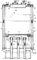
- Conveyor 16 comprises three permeable belts 17 (Fig.2), each having a number of through holes 18, and each looped about two pulleys 19 and 20 defining, on conveyor 16, a forward branch 21 and a return branch 22, each narrower than strip 14.
- Pulley 19 is a known type of suction pulley comprising a powered outer rim 23 having a number of radial through holes 24 at and/or between belts 17, and mounted on a fixed inner drum 25 so as to rotate anticlockwise (in Fig. 1) about drum 25 and move forward branch 21 of conveyor 16 in direction 26 extending parallel to the Fig.2 plane, perpendicular to the respective axes of wheels 2 and 6, and vertically upwards towards station 5.
- Drum 25 presents an outer chamber 27 extending over the arc of contact between rim 23 and belts 17 and communicating with a suction conduit 28 formed centrally through drum 25.
- Cutting device 31 comprises two fixed blades 32 aligned on either side of box 30 between branches 21 and 22; and two movable blades 33 projecting radially outwards from the periphery of a powered roller 34 rotating clockwise (in Fig.1) about an axis perpendicular to the Fig.1 plane and parallel to the respective axes of wheels 2 and 6.
- Pulleys 20 are fitted on to the same shaft 35 located between the forward branch 36, facing wheel 2, and the return branch 37, facing wheel 6, of a second conveyor 38 extending vertically through station 5 and between wheels 2 and 6.
- Conveyor 38 comprises two shafts 39 and 40 parallel to each other and to shaft 35, and located at the opposite ends of a supporting frame 41 extending through station 5. More specifically, shaft 39 extends in the gap between branches 21 and 22 of conveyor 16; and one of shafts 39, 40 is powered for moving forward branch 36 of conveyor 38 in vertical direction 42 parallel to direction 26. The opposite ends of shafts 39 and 40 are fitted with respective pairs of pulleys 43 and 44 supporting two looped belts 45 parallel to each other and to belts 17 and separated by a distance greater than the width of strip 14.
- Frame 41 comprises two suction boxes 46 located inside the forward and return branches of each belt 45 and communicating with suction conduits (not shown) formed through appendixes 47 integral with and extending from each belt 45 towards the other belt 45.
- Each appendix 47 corresponds with an appendix 47 on the other belt 45, so that the distance between each pair of corresponding appendixes 47 is less than the width of strip 14.
- each appendix 47 presents, on the outward-facing surface, a number of suction holes 48 communicating with said suction conduits (not shown).
- Said outer surfaces of appendixes 47 define, along forward branch 36 of conveyor 38, a transportation surface 49 of conveyor 38.
- the central portion of shaft 40 is fitted with a roller 40a positioned facing a pair of gumming devices 12.
- Cutting device 50 comprises a fixed blade 51 mounted outwards of conveyor 38, facing branch 36, and parallel to shafts 39 and 40, and which presents a cutting edge facing and slightly outwards of transportation surface 49.
- device 51 comprises a corresponding movable blade 52 projecting radially outwards from the periphery of a powered roller 53 supported on boxes 46 between branches 36 and 37 and rotating anticlockwise in Fig.1 about an axis perpendicular to the Fig.1 plane and parallel to the respective axes of wheels 2 and 6.
- fixed blade 51 is located immediately downstream, in direction 42, from a cutting station 54 extending between shaft 35 and fixed blade 51 along forward branch 36 of conveyor 38.
- cutting device 50 comprises a detaching member 55 having a suction device 56 and located outwards of conveyor 38, on the same side as fixed blade 51, so as to oscillate between a gripping position, wherein member 55 is substantially coplanar with the cutting edge of fixed blade 51, and an operating position wherein member 55 is substantially coplanar with transportation surface 49.
- feed device 9 comprises a known type of folding spindle 57 defining a passage 58 of the same section as pockets 3 and seats 7.
- strip 14 contacts conveyor 16 on the outer surface of pulley 19, which, by virtue of the suction through holes 24 in rim 23, feeds the leading end of strip 14 to forward branch 21 of conveyor 16.
- strip 14 is held contacting belts 17 by the suction through wall 29 of box 30, and, if necessary, is engaged by cutting device 31, which makes two partial lateral cuts (not shown) in strip 14 for defining, on strip 14, the end folds (not shown) of portions 8 to be cut off strip 14.
- cutting device 31 is deactivated or eliminated when, as is often the case with transparent wrapping material, no end folds are required on portions 8.
- the leading end of strip 14 travels along the whole of forward branch 21 to transportation surface 49, which is coplanar with the outer surface of the portion of belts 17 extending along forward branch 21.
- the leading end of strip 14 reaches transportation surface 49 simultaneously with a pair of appendixes 47 which are engaged by a leading portion of strip 14 by virtue of the suction through holes 48.
- Conveyors 16 and 38 which are operated in steps and at the same speed, are stopped upon said pair of appendixes 47 reaching cutting station 54, and for as long as required for enabling cutting device 50 (as explained later) to perform a cutting operation, which, at least in this first case, is superfluous by virtue of the leading end of strip 14 being arrested facing the cutting edge of fixed blade 51.
- a further operating step of conveyor 38 feeds said pair of appendixes 47 up to the periphery of roller 40a, so that the leading end of strip 14 is drawn through transfer station 5 and into engagement with gumming devices 12, which provide for gumming given portions of surface 13 on the end portion of strip 14.
- a product 4, housed inside pocket 3 in station 5, is extracted from pocket 3 in a direction perpendicular to transportation surface 49, and fed between belts 45 and through spindle 57 into a corresponding seat 7 also located in station 5 and facing respective pocket 3.
- product 4 engages and detaches portion 8 from respective appendixes 47, folds it in a U as it moves through spindle 57, and feeds it, so folded, into seat 7 so that two end portions (not shown) of portion 8 project from seat 7, and one of which is gummed on the side facing the other end portion.
- Folding devices 10 and 11 then fold the two end portions (not shown) one on top of the other, with the gummed end portion (not shown) on the outside, to produce a tubular wrapping (not shown) about product 4.
Landscapes
- Engineering & Computer Science (AREA)
- Mechanical Engineering (AREA)
- Basic Packing Technique (AREA)
- Auxiliary Devices For And Details Of Packaging Control (AREA)
Applications Claiming Priority (2)
| Application Number | Priority Date | Filing Date | Title |
|---|---|---|---|
| ITBO910452A IT1253901B (it) | 1991-12-03 | 1991-12-03 | Metodo e dispositivo di alimentazione di spezzoni di materiale di incarto ad una macchina incartatrice |
| ITBO910452 | 1991-12-03 |
Publications (3)
| Publication Number | Publication Date |
|---|---|
| EP0545265A2 true EP0545265A2 (fr) | 1993-06-09 |
| EP0545265A3 EP0545265A3 (en) | 1993-09-08 |
| EP0545265B1 EP0545265B1 (fr) | 1998-02-11 |
Family
ID=11337857
Family Applications (1)
| Application Number | Title | Priority Date | Filing Date |
|---|---|---|---|
| EP92120123A Expired - Lifetime EP0545265B1 (fr) | 1991-12-03 | 1992-11-25 | Procédé et dispositif d'alimentation en matériau d'emballage d'une machine à emballer |
Country Status (7)
| Country | Link |
|---|---|
| US (1) | US5386679A (fr) |
| EP (1) | EP0545265B1 (fr) |
| JP (1) | JP2551717B2 (fr) |
| CN (1) | CN1034270C (fr) |
| BR (1) | BR9204651A (fr) |
| DE (1) | DE69224425T2 (fr) |
| IT (1) | IT1253901B (fr) |
Cited By (1)
| Publication number | Priority date | Publication date | Assignee | Title |
|---|---|---|---|---|
| DE19650182A1 (de) * | 1996-12-04 | 1998-06-10 | Topack Verpacktech Gmbh | Fördervorrichtung für Hüllmaterial |
Families Citing this family (2)
| Publication number | Priority date | Publication date | Assignee | Title |
|---|---|---|---|---|
| CN110902010B (zh) * | 2019-12-26 | 2022-05-17 | 厦门商集网络科技有限责任公司 | 一种票据自动封装装置 |
| CN113682551B (zh) * | 2021-08-30 | 2022-09-13 | 陕西科技大学 | 一种可自动上下料的包装机 |
Family Cites Families (18)
| Publication number | Priority date | Publication date | Assignee | Title |
|---|---|---|---|---|
| US2603925A (en) * | 1948-10-14 | 1952-07-22 | Moore George Arlington | Heat-sealing wrapping machine |
| US3150475A (en) * | 1960-06-29 | 1964-09-29 | Textile Machine Works | Banding machine |
| US3177746A (en) * | 1961-04-10 | 1965-04-13 | Langer Herbert | Film dispensing method and apparatus having gripper means to pull the film across a cutting station |
| GB1094351A (en) * | 1964-06-04 | 1967-12-13 | Schmermund Alfred | Improvements in or relating to wrapping machines |
| GB1071205A (en) * | 1965-05-22 | 1967-06-07 | Schmermund Alfred | Improvements in or relating to packing machines |
| US3355166A (en) * | 1965-06-24 | 1967-11-28 | St Regis Paper Co | Automatic wrapping machine including a suction stop plate |
| DE1932360A1 (de) * | 1969-06-26 | 1971-01-07 | Hauni Werke Koerber & Co Kg | Verfahren und Vorrichtung zum Zufuehren eines ununterbrochenen Stromes aus Materialabschnitten zu einer Tabakartikel verarbeitenden Einrichtung |
| DE1963956A1 (de) * | 1969-12-20 | 1971-08-05 | Bengs Senning Geb Senning | Verfahren und Vorrichtung zum Zufuehren von Folienabschnitten zu einer Verarbeitungsstelle,insbesondere in Packmaschinen |
| CH553688A (de) * | 1972-07-03 | 1974-09-13 | Sig Schweiz Industrieges | Vorrichtung zum zufuehren von einschlagfolien an einer verpackungsmaschine. |
| DE2410587C2 (de) * | 1974-03-06 | 1981-09-17 | Martin 3051 Horst Natusch | Einwickelmaschine |
| US4388794A (en) * | 1975-07-11 | 1983-06-21 | Focke & Pfuhl | Apparatus for cutting and transporting blanks from a web of flexible material |
| DE2949685A1 (de) * | 1979-12-11 | 1981-06-19 | Focke & Co, 2810 Verden | Vorrichtung zum herstellen von packungszuschnitten durch abtrennen von einer fortlaufenden bahn |
| US4336680A (en) * | 1980-01-04 | 1982-06-29 | Nordson Corporation | Stainless steel transport band |
| DE3131687A1 (de) * | 1981-08-11 | 1983-03-03 | Focke & Co, 2810 Verden | "verpackungs-vorrichtung zum herstellen von zuschnitten und zufuehren derselben in einer verpackungsstation" |
| DE3241636A1 (de) * | 1982-11-11 | 1984-05-17 | Focke & Co, 2810 Verden | Vorrichtung zum herstellen von verpackungszuschnitten |
| IT1207733B (it) * | 1987-06-23 | 1989-05-25 | Gd Spa | Metodo per la produzione di pacchetti di sigarette dotati di un involucro a tenuta ermetica |
| NL8702623A (nl) * | 1987-11-03 | 1989-06-01 | Sollas Holland Bv | Toestel voor het afmeten van een foeliestrook voor het verpakken van op een horizontale ondersteuning aangevoerde voorwerpen. |
| DE3800432A1 (de) * | 1988-01-09 | 1989-07-20 | Hauni Werke Koerber & Co Kg | Vorrichtung zum einhuellen von packungen mit huellmaterial |
-
1991
- 1991-12-03 IT ITBO910452A patent/IT1253901B/it active IP Right Grant
-
1992
- 1992-11-25 EP EP92120123A patent/EP0545265B1/fr not_active Expired - Lifetime
- 1992-11-25 DE DE69224425T patent/DE69224425T2/de not_active Expired - Fee Related
- 1992-12-02 BR BR9204651A patent/BR9204651A/pt active Search and Examination
- 1992-12-02 US US07/985,179 patent/US5386679A/en not_active Expired - Fee Related
- 1992-12-03 CN CN92113741.9A patent/CN1034270C/zh not_active Expired - Fee Related
- 1992-12-03 JP JP4324420A patent/JP2551717B2/ja not_active Expired - Lifetime
Cited By (3)
| Publication number | Priority date | Publication date | Assignee | Title |
|---|---|---|---|---|
| DE19650182A1 (de) * | 1996-12-04 | 1998-06-10 | Topack Verpacktech Gmbh | Fördervorrichtung für Hüllmaterial |
| EP0846619A1 (fr) | 1996-12-04 | 1998-06-10 | TOPACK Verpackungstechnik GmbH | Dispositif pour le transport de feuilles de matériau d'enveloppement |
| US6023911A (en) * | 1996-12-04 | 2000-02-15 | Topack Verpackungstechnik Gmbh | Apparatus for transporting webs of wrapping material |
Also Published As
| Publication number | Publication date |
|---|---|
| EP0545265A3 (en) | 1993-09-08 |
| JP2551717B2 (ja) | 1996-11-06 |
| BR9204651A (pt) | 1993-06-08 |
| JPH06286728A (ja) | 1994-10-11 |
| CN1073147A (zh) | 1993-06-16 |
| IT1253901B (it) | 1995-08-31 |
| DE69224425D1 (de) | 1998-03-19 |
| US5386679A (en) | 1995-02-07 |
| CN1034270C (zh) | 1997-03-19 |
| ITBO910452A1 (it) | 1993-06-03 |
| DE69224425T2 (de) | 1998-06-18 |
| ITBO910452A0 (it) | 1991-12-03 |
| EP0545265B1 (fr) | 1998-02-11 |
Similar Documents
| Publication | Publication Date | Title |
|---|---|---|
| US4962897A (en) | Web winding machine and method | |
| US4495746A (en) | Packaging apparatus for producing and feeding blanks to a packaging station | |
| US4385479A (en) | Apparatus for the preparation of packaging blanks by severing from a continuous web | |
| US4856725A (en) | Web winding machine and method | |
| CA1299417C (fr) | Appareil servant a la production et au transport de decoupes de paquetsde cigarettes et procede connexe | |
| US4524658A (en) | Apparatus for producing packaging blanks | |
| US4561928A (en) | Labelling machine | |
| US4526645A (en) | Labelling equipment | |
| EP0944528B1 (fr) | Appareil d'etiquetage en rouleau | |
| US4447280A (en) | Labelling machine | |
| EP0199285A2 (fr) | Bobineuse pour matériau en bande et procédé de bobinage | |
| US3982375A (en) | Process and a device for wrapping articles, more particularly, groups of cigarettes | |
| EP0465256A1 (fr) | Appareil pour transférer des bandes de matériel sur une bande de papier | |
| US4351142A (en) | Apparatus for wrapping objects, in particular groups of cigarettes | |
| US4603534A (en) | Apparatus for wrapping articles, especially cigarette groups | |
| US5845464A (en) | Product wrapping method | |
| JP2015078017A (ja) | 製品の各々が単一の包囲体に包まれるように製品を連続的に包装する自動包装機及び方法 | |
| JPH0672409A (ja) | 包装材料の供給方法及び装置 | |
| EP0545265B1 (fr) | Procédé et dispositif d'alimentation en matériau d'emballage d'une machine à emballer | |
| US5461954A (en) | Method and device for feeding portions of wrapping material to a packing line | |
| EP1547927A2 (fr) | Dispositif d'alimentation et de coupe de bande pour machine d'emballage | |
| JPH10218123A (ja) | シガレット群或いはシガレットパッケージのためのくるみ材料テープを送るための装置 | |
| EP0787651A1 (fr) | Procédé pour alimenter des feuilles de matériau d'enveloppement | |
| US5327702A (en) | Wrapping articles | |
| GB2290533A (en) | Wrapping articles |
Legal Events
| Date | Code | Title | Description |
|---|---|---|---|
| PUAI | Public reference made under article 153(3) epc to a published international application that has entered the european phase |
Free format text: ORIGINAL CODE: 0009012 |
|
| AK | Designated contracting states |
Kind code of ref document: A2 Designated state(s): DE FR GB IT |
|
| PUAL | Search report despatched |
Free format text: ORIGINAL CODE: 0009013 |
|
| AK | Designated contracting states |
Kind code of ref document: A3 Designated state(s): DE FR GB IT |
|
| 17P | Request for examination filed |
Effective date: 19940222 |
|
| 17Q | First examination report despatched |
Effective date: 19941114 |
|
| GRAG | Despatch of communication of intention to grant |
Free format text: ORIGINAL CODE: EPIDOS AGRA |
|
| APAB | Appeal dossier modified |
Free format text: ORIGINAL CODE: EPIDOS NOAPE |
|
| APAD | Appeal reference recorded |
Free format text: ORIGINAL CODE: EPIDOS REFNE |
|
| GRAH | Despatch of communication of intention to grant a patent |
Free format text: ORIGINAL CODE: EPIDOS IGRA |
|
| GRAH | Despatch of communication of intention to grant a patent |
Free format text: ORIGINAL CODE: EPIDOS IGRA |
|
| GRAA | (expected) grant |
Free format text: ORIGINAL CODE: 0009210 |
|
| AK | Designated contracting states |
Kind code of ref document: B1 Designated state(s): DE FR GB IT |
|
| ITF | It: translation for a ep patent filed | ||
| REF | Corresponds to: |
Ref document number: 69224425 Country of ref document: DE Date of ref document: 19980319 |
|
| ET | Fr: translation filed | ||
| PG25 | Lapsed in a contracting state [announced via postgrant information from national office to epo] |
Ref country code: GB Free format text: LAPSE BECAUSE OF NON-PAYMENT OF DUE FEES Effective date: 19981125 |
|
| PLBE | No opposition filed within time limit |
Free format text: ORIGINAL CODE: 0009261 |
|
| STAA | Information on the status of an ep patent application or granted ep patent |
Free format text: STATUS: NO OPPOSITION FILED WITHIN TIME LIMIT |
|
| 26N | No opposition filed | ||
| GBPC | Gb: european patent ceased through non-payment of renewal fee |
Effective date: 19981125 |
|
| PG25 | Lapsed in a contracting state [announced via postgrant information from national office to epo] |
Ref country code: FR Free format text: LAPSE BECAUSE OF NON-PAYMENT OF DUE FEES Effective date: 19990730 |
|
| REG | Reference to a national code |
Ref country code: FR Ref legal event code: ST |
|
| PG25 | Lapsed in a contracting state [announced via postgrant information from national office to epo] |
Ref country code: DE Free format text: LAPSE BECAUSE OF NON-PAYMENT OF DUE FEES Effective date: 19990901 |
|
| APCB | Communication from the board of appeal sent |
Free format text: ORIGINAL CODE: EPIDOS OBAPE |
|
| APCB | Communication from the board of appeal sent |
Free format text: ORIGINAL CODE: EPIDOS OBAPE |
|
| APAC | Appeal dossier modified |
Free format text: ORIGINAL CODE: EPIDOS NOAPO |
|
| APAH | Appeal reference modified |
Free format text: ORIGINAL CODE: EPIDOSCREFNO |
|
| PG25 | Lapsed in a contracting state [announced via postgrant information from national office to epo] |
Ref country code: IT Free format text: LAPSE BECAUSE OF NON-PAYMENT OF DUE FEES;WARNING: LAPSES OF ITALIAN PATENTS WITH EFFECTIVE DATE BEFORE 2007 MAY HAVE OCCURRED AT ANY TIME BEFORE 2007. THE CORRECT EFFECTIVE DATE MAY BE DIFFERENT FROM THE ONE RECORDED. Effective date: 20051125 |