EP0545341B1 - Récepteur de télévision - Google Patents
Récepteur de télévision Download PDFInfo
- Publication number
- EP0545341B1 EP0545341B1 EP19920120420 EP92120420A EP0545341B1 EP 0545341 B1 EP0545341 B1 EP 0545341B1 EP 19920120420 EP19920120420 EP 19920120420 EP 92120420 A EP92120420 A EP 92120420A EP 0545341 B1 EP0545341 B1 EP 0545341B1
- Authority
- EP
- European Patent Office
- Prior art keywords
- image
- scanning lines
- aspect ratio
- squeeze
- scanning
- Prior art date
- Legal status (The legal status is an assumption and is not a legal conclusion. Google has not performed a legal analysis and makes no representation as to the accuracy of the status listed.)
- Expired - Lifetime
Links
- 230000015654 memory Effects 0.000 claims description 43
- 238000006243 chemical reaction Methods 0.000 claims description 23
- 230000006835 compression Effects 0.000 claims description 2
- 238000007906 compression Methods 0.000 claims description 2
- 229940028444 muse Drugs 0.000 description 10
- GMVPRGQOIOIIMI-DWKJAMRDSA-N prostaglandin E1 Chemical compound CCCCC[C@H](O)\C=C\[C@H]1[C@H](O)CC(=O)[C@@H]1CCCCCCC(O)=O GMVPRGQOIOIIMI-DWKJAMRDSA-N 0.000 description 10
- 230000004044 response Effects 0.000 description 8
- 238000010586 diagram Methods 0.000 description 4
- 238000001514 detection method Methods 0.000 description 3
- 238000000034 method Methods 0.000 description 3
- 230000006866 deterioration Effects 0.000 description 2
- 230000006978 adaptation Effects 0.000 description 1
- 230000001419 dependent effect Effects 0.000 description 1
Images





Classifications
-
- H—ELECTRICITY
- H04—ELECTRIC COMMUNICATION TECHNIQUE
- H04N—PICTORIAL COMMUNICATION, e.g. TELEVISION
- H04N7/00—Television systems
- H04N7/01—Conversion of standards, e.g. involving analogue television standards or digital television standards processed at pixel level
- H04N7/0117—Conversion of standards, e.g. involving analogue television standards or digital television standards processed at pixel level involving conversion of the spatial resolution of the incoming video signal
- H04N7/0122—Conversion of standards, e.g. involving analogue television standards or digital television standards processed at pixel level involving conversion of the spatial resolution of the incoming video signal the input and the output signals having different aspect ratios
Definitions
- the present invention generally relates to a television receiver. More specifically, the present invention relates to a television receiver in which a squeeze image having an aspect ratio 16:9 or a standard television image having an aspect ratio 4:3 can be displayed on a screen having an aspect ratio 4:3. Description of the prior art
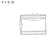
- an output of the converter that is, a squeeze image having an aspect ratio 16:9 is displayed on a screen having an aspect ratio 4:3 in a letter-box form as shown in Figure 13.
- the number of effective scanning lines of a standard television image of an NTSC system that is of an aspect ratio 4:3, is 480
- a television receiver according to the precharacterizing part of claim 1 is disclosed in GB-A-2186165.
- a cathode ray tube video display device is adapted to display wide aspect ratio signals by reducing the vertical scanning amplitude of the scanning raster.
- the scan is collapsed in the vertical direction without reducing the number of lines used to display the active picture, leaving unscanned bands at the top and bottom of the display.
- the device can change between a normal raster scanning mode and such a collapsed wide screen mode automiatically in response to a flag in the received video signal.
- a principal object of the present invention is to provide a television receiver in which no deterioration occurs in the vertical resolution even if a squeeze image having an aspect ratio 16:9 is displayed on a screen having an aspect ratio 4:3.
- the squeeze image signal having the aspect ratio 4:3 is obtained from the converter.
- an image signal of the image having the second aspect ratio is received by the television receiver, and the image signal having the second aspect ratio is converted into the squeeze image signal having the first aspect ratio in the image conversion means.
- the squeeze image having the first aspect ratio is further vertically compressed in a time axis by the image conversion means.
- the image conversion means includes a field memory, for example, and the squeeze image signal having the first aspect ratio is written in the field memory in response to a write clock and then read-out in response to a read clock that is a predetermined multiplication of the write clock so that the squeeze image having the first aspect ratio is vertically compressed so as to become a squeeze image signal having the second aspect ratio.
- scanning lines are added to the squeeze image signal having the second aspect ratio for blanking portions, and therefore, the squeeze image having the second aspect ratio is displayed on the display screen having the first aspect ratio in a letter-box form, for example.
- the scanning line conversion means the number of scanning lines of the standard television image having the first aspect ratio is converted into the number of scanning lines of the squeeze image having the second aspect ratio.
- the scanning line conversion means includes a plurality of line memories, for example, and image signal of respective lines are written in the line memories in response to a write clock and then read-out in response to a read clock that is a predetermined multiplication of the write clock, and the image signal of the respective lines read from the line memories are applied to an interpolation filter by which scanning line interpolation can be performed. If the number of scanning lines of the squeeze image having the second aspect ratio is N, the number of scanning lines of the standard television image, for example, PAL, NTSC or the like is converted into N.
- the number of scanning lines of the squeeze image and the number of scanning lines of the standard television image becomes coincident with each other, it is possible to display the squeeze image and the standard television image with utilizing a common vertical deflection system when a CRT is used.
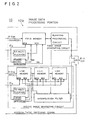
- a television receiver 10 includes image data processing portions 12a, 12b and 12c which respectively perform the processing of a Y component, an R-Y component and a B-Y component all included in the input image data. Since the image data processing portions 12a, 12b and 12c are similar to each other in structure and operation thereof while the data components to be processed are different from each other, in the following, only the image data processing portion 12a will be described in detail, and descriptions of the image data processing portions 12b and 12c will be omitted.
- the image data processing portion 12a shown in Figure 1 includes a first image data generating circuit 14 which generates image data of a squeeze image having an aspect ratio 16:9 on the basis of squeeze image data applied by a MUSE/NTSC converter (not shown), and a second image data generating circuit 16 which generates image data of an NTSC television image having an aspect ratio 4:3 through a scanning line conversion on the basis of the number of scanning lines of the image data generated by the first image data generating circuit 14.
- the squeeze image having an aspect ratio 4:3 that is outputted from the MUSE/NTSC converter is compressed in a vertical direction so that a squeeze image having an aspect ratio 16:9 and the number of scanning lines as the same as the squeeze image having an aspect ratio 4:3 can be generated.
- a time axis compression as shown in Figure 4, circles which become longitudinal circles in the squeeze image having an aspect ratio 4:3 becomes complete rounds that are the same as that of an original image.
- the squeeze image having an aspect ratio 4:3 is displayed as it is on the display screen having an aspect ratio 4:3, the squeeze image is displayed as shown in Figure 5. More specifically, in a vertical direction, by thinning the scanning lines of 960 out of the effective scanning lines of 1032 of the MUSE signal for every two lines, the scanning lines of 480 are formed. Therefore, in a case of Figure 5, an upper end and lower end of the squeeze image having an aspect ratio 4:3 are respectively broken slightly with respect to the original image. On the other hand, in a horizontal direction, no drop-out occurs in the image because one horizontal period of the MUSE signal becomes one horizontal scanning line of the NTSC television image as it is.
- N (1032/960) x 480 x (12/9) x (1/0.945) ⁇ 728 [lines]
- the number of scanning lines L of the squeeze image having an aspect ratio 16:9 becomes 796 lines.
- the number of scanning lines of 525 and the number of effective scanning lines of 480 of the NTSC television image may be converted into the number of scanning lines of 796 and the number of effective scanning lines of 728, respectively.
- the first image generating circuit 14 further includes a field memory 18 which temporarily stores the Y component data of the squeeze image having an aspect ratio and being outputted from the MUSE/NTSC converter (not shown).
- a clock signal ⁇ D is inputted to the first image generating circuit 14 from a PLL (Phase Locked Loop) for a horizontal clock of the MUSE/NTSC decoder, and the Y component data of the squeeze image having an aspect ratio 4:3 is written in the field memory 18 by utilizing the clock signal ⁇ D as a write clock.
- the clock signal ⁇ D is further inputted to a timing signal generating circuit 20.
- the timing signal generating circuit 20 generates a write reset signal WR on the basis of the clock signal ⁇ D , and in response to the write reset signal WR, the writing of the field memory 18 is reset.
- the Y component data of one field of the squeeze image are written.
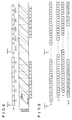
- write timings of the squeeze image data is shown by solid lines.
- the clock signal ⁇ D is further inputted to a 7/5 multiplication circuit 22 to be multiplied by 7/5, and a multiplied clock signal is applied to the field memory 18 as a read clock therefor and inputted to the timing signal generating circuit 20.
- the timing signal generating circuit 20 In response to the read clock applied from the 7/5 multiplication circuit 22 to the field memory 18, the image data stored in the field memory 18 are read-out.
- the timing signal generating circuit 20 generates a read reset signal RR on the basis of the read clock inputted from the 7/5 multiplication circuit 22 and, in response to the read reset signal RR, the reading of the field memory 18 is reset.
- read timings of the squeeze image data is shown by dotted lines.
- the squeeze image data thus written in the field memory 18 and read from the field memory 18 becomes image data of an image (x', y' and z' shown in Figure 7) that is obtained by vertically compressing the original image (x, y and z shown in Figure 7) by 5/7.
- image data read from the field memory 18 is applied to a blanking processing circuit 24 in which the predetermined number of scanning lines for blanking portions are added to the upper and lower portions of the image so that no image portion becomes to be included in a blanking period.
- the squeeze image data is outputted by which an image constituted by an image portion of an aspect ratio 16:9 and blanking portions at the upper and lower portions of the image as shown in Figure 6 is displayed on the display screen having an aspect ratio 4:3.
- An output of the first image generating circuit 14 is applied to one input 26a of a switch circuit 26.
- the NTSC image data is inputted to the second image generating circuit 16 and written in a line memory 30a.
- a clock signal ⁇ N is inputted to the second image generating circuit 16 from a PLL for a horizontal clock of the NTSC television signal, and the NTSC image data of one scanning line are written in the line memory 30a by utilizing the clock signal ⁇ N as a write clock.
- the clock signal ⁇ N is further inputted to a timing signal generating circuit 32.
- the timing signal generating circuit 32 generates a write reset signal WR on the basis of the clock signal ⁇ N so as to send the same to the line memory 30a. Therefore, as shown by a solid line in Figure 8, the NTSC image data of one scanning line of one vertical period of 15 kHz are written in the line memory 30a.
- the number of scanning lines of the NTSC image data In order to make the number of scanning lines of the NTSC image data coincident with the number of scanning lines of the output data from the first image generating circuit 14, as mentioned above, the number of scanning lines must be multiplied by 7/5. Therefore, it is necessary to read-out the NTSC image data of 7 scanning lines from the line memory 30a within 5 horizontal periods of the original image data. Therefore, the clock signal ⁇ N is applied to 7/5 multiplication circuit 34 to be multiplied by 7/5. Then, an output of the 7/5 multiplication circuit 34 is sent to the line memory 30a as a read clock therefor, and inputted to the timing signal generating circuit 32. The timing signal generating circuit 32 generates a read reset signal RR on the basis of the output of the 7/5 multiplication circuit 34.
- the NTSC image data for one horizontal period of the original NTSC image data are read from the line memory 30a. That is, the image data for 7 scanning lines having a horizontal frequency of 21 kHz are read-out from the line memory 30a within 5 horizontal periods of the original NTSC image data.
- the output from the 7/5 multiplication circuit 34 is also inputted to line memories 30b and 30c (described later) as write clocks and read clocks, and a signal inputted to the line memory 30a as the read reset signal RR from the timing signal generating circuit 32 is further applied to the line memories 30b and 30c as both write reset signals and read reset signals therefor.
- the image data read from the line memory 30a (the image data of X point in Figure 1) includes the image data of 7 scanning lines within 5 horizontal periods of the original NTSC image data, and therefore, as shown in Figure 9, the same image data may be duplicated. It is not preferable that such duplicate data are used as they are as image data for display, and therefore, the image data from the line memory 30a is written in the line memory 30b and read-out by delaying by one horizontal period.
- the image data (the image data of Y point in Figure 1) read from the line memory 30b is written in the line memory 30c and read-out by delaying by further one horizontal period. Therefore, the image data from the line memory 30c becomes the image data of Z point in Figure 1.
- a/b, b/c, c/d, ... are weighted mean values, respectively.
- the image data of X point, Y point and Z point shown in Figure 1 are inputted to an interpolation filter 36.
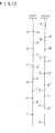
- interpolation filter 36 scanning line interpolation processing as shown in Figure 10 is performed. More specifically, in a first field and a second field succeeding to the first field, in order to generate 7 scanning lines within 5 horizontal periods of the original NTSC image data, by utilizing outputs of the line memories 30a, 30b and 30c, interpolated scanning lines are generated.
- the image data of the scanning line after conversion that is positioned between the scanning lines of the original NTSC image data when the scanning lines of the original NTSC image data and the scanning lines after conversion are overlapped each other can be evaluated by calculating weighted means values of the image data of the scanning lines of the NTSC image data sandwiching the scanning line after conversion.
- the image data b' of the scanning line after conversion in the first field is a weighted mean value of the data a and b of the scanning lines of the original NTSC image.
- the scanning line B' is a weighted mean value of the scanning lines C and D.
- the image data shown in Figure 9 are outputted from the interpolation filter 36, and resultingly, 525 scanning lines of the original NTSC image data is converted into 735 scanning lines.
- An output of the interpolation filter 36, that is, an output of the second image generating circuit 16 is applied to another input 26b of the switch circuit 26.
- the switch circuit 26 is switched by a hivision/NTSC changing signal. More specifically, in a first mode for displaying the squeeze image from the MUSE/NTSC converter, the switch circuit 26 selects the first input 26a, that is, the output of the first image generating circuit 14. Therefore, in the first mode, the squeeze image having an aspect ratio 16:9 is displayed on the display screen having an aspect ratio 4:3 in a letter-box form.
- the switch circuit 26 selects the other input 26b, that is, the output of the second image generating circuit 16. Therefore, in the second mode, the NTSC image having an aspect ratio 4:3 is displayed on the display screen having an aspect ratio 4:3.
- the number of the scanning lines of the NTSC image having an aspect ratio 4:3 is converted into 735 lines that is the number of the scanning lines of the squeeze image having an aspect ratio 16:9, and therefore, it is possible to display the NTSC image as well as the squeeze image by utilizing a signal vertical deflection circuit system of 22 kHz, for example, even if a CRT is used for the display screen having an aspect ratio 4:3.
- the scanning line interpolation is performed within the same field; however, in order to interpolate scanning lines in a movement adaptation manner, mean values may be calculated on the basis of data of succeeding fields, as done in Figure 11 embodiment.
- a scanning line interpolation circuit 38 receives an analog television signal having the scanning lines of 525 of the NTSC image from an input terminal 40.
- the analog television signal is converted into television signal data by an A/D converter 42 so as to be applied to an interpolation filter for still picture 44, interpolation filter for moving picture 46 and a movement detection circuit 48.
- the image data constituted by 525 scanning lines is converted into image data constituted by 735 scanning lines, being applied to a mixer 50.
- the A/D converter 40 may be omitted.
- the movement detection circuit 48 determines whether respective areas of the image is a still picture or a moving picture on the basis of the input image data for each area, and a determination signal is applied to the mixer 50 from the movement detection circuit 48.
- the mixer 50 according to the determination signal of the respective areas, the image data formed by 735 scanning lines respectively supplied from the interpolation filter for still picture 44 and the interpolation filter for moving picture 46 are mixed in a predetermined mixing ratio. Then, an output of the mixer 50 is inputted to a D/A converter 52 and outputted from an output terminal 54.
- the D/A converter 52 and the output terminal 54 may be omitted.
- a, b, c, d, e and f denote m-th line, (m+1)th line, (m+2)th line, (m+3)th line, (m+4)th line and (m+5)th line of 525 scanning lines in the first field.
- A, B, C, D, E, F and G denote M-th line, (M+1)th line, (M+2)th line, (M+3)th line, (M+4)th line, (M+5)th line and (M+6)th line in the 525 scanning lines of the second field.
- a', b', c', d', e', f' and g' denote n-th line, (n+1)th line, (n+2)th line, (n+3)th line, (n+4)th line, (n+5)th line and (n+6)th line in the 735 scanning lines of the first filed after scanning line interpolation.
- A', B', C', D', E', F' and G' denote N-th line, (N+1)th line, (N+2)th line, (N+3)th line, (N+4)th line, (N+5)th line and (N+6)th line.
- the scanning line interpolation is performed by utilizing the scanning lines of the both of the first field and the second field.
- the interpolation filter for moving picture 46 the scanning line interpolation is performed so as to satisfy the relationships represented by the following equations.
- c' 4 x (b/7) + 3 x (C/7)
- d' 6 x (c/7) + 1 x (D/7)
- e' 1 x (c/7) + 6 x (d/7)
- f' 3 x (d/7) + 4 x (e/7)
- g' 5 x (e/7) + 2 x (f/7)
- A' 1 x (A/7) + 6 x (B/7)
- B' 3 x (B/7) + 4 x (C/7)
- C' 5 x (C/7) + 2 x (D/7)
- F' 4 x (E/7) + 3 x (F/
- the interpolation operation is performed by utilizing the scanning line lines within the same field.
- an image signal of an image having an aspect ratio 16:9 is broad-casted. Therefore, in a case-where such PAL+ or HD-MAC television image is to be displayed on the display screen having an aspect ratio 4:3, it is possible to use the present invention.
- a received image having an aspect ratio 16:9 is converted into a squeeze image having an aspect ratio 4:3 that is equivalent to the output of the MUSE/NTSC converter of the in the above described embodiment, and then, the squeeze image having an aspect ratio 4:3 is vertically compressed so that the squeeze image having an aspect ratio 16:9 can be obtained.
Landscapes
- Engineering & Computer Science (AREA)
- Computer Graphics (AREA)
- Multimedia (AREA)
- Signal Processing (AREA)
- Television Systems (AREA)
Claims (7)
- Récepteur de télévision qui comporte un écran d'affichage ayant un premier format d'image et susceptible d'afficher un signal d'image ayant un second format d'image qui est différent dudit premier format d'image sur ledit écran d'affichage,
caractérisé en ce que ledit récepteur de télévison (10) comprend en outre:des moyens de conversion d'image (14, 18, 22, 24) pour générer un signal d'image de serrage ayant ledit second format d'image et un nombre prédéterminé de lignes de balayage en comprimant un signal d'image de serrage ayant ledit premier format d'image dans un sens vertical et en additionnant des périodes de suppression à une extrémité supérieure et une extrémité inférieure d'un signal d'image de serrage comprimé;des moyens de conversion de ligne de balayage (16) pour convertir le nombre de lignes de balayage d'un signal d'image de télévision standard ayant ledit premier format d'image en un nombre prédéterminé de lignes de balayage dudit signal d'image de serrage généré par lesdits moyens de conversion d'image; etdes moyens de sélection (26) pour sélectionner une sortie desdits moyens de conversion d'image dans un premier mode pour afficher le signal de serrage ayant ledit second format d'image ou une sortie desdits moyens de conversion de ligne de balayage dans un second mode pour afficher l'image ayant ledit premier format d'image. - Récepteur de télévision selon la revendication 1, dans lequel lesdits moyens de conversion d'image (14, 18, 22, 24) comportentune mémoire (18),un moyen d'écriture (20, φD) pour écrire le signal d'image de serrage ayant ledit premier format d'image dans ladite mémoire avec une horloge d'écriture,un moyen de lecture (20, 22) pour lire le signal d'image de serrage de ladite mémoire avec une horloge de lecture qui est une multiplication prédéterminée de ladite horloge d'écriture, etun moyen d'addition de période de suppression (24) pour additionner des lignes de balayage pour lesdites périodes de suppression aux lignes de balayage dudit signal d'image de serrage lu à partir de ladite mémoire.
- Récepteur de télévision selon l'une quelconque des revendications 1 ou 2, dans lequel lesdits moyens de conversion de ligne de balayage (16) convertissent le nombre des lignes de balayage de ladite image de télévision standard en un nombre des lignes de balayage dudit signal d'image de serrage ayant ledit second format d'image et étant fourni en sortie à partir desdits moyens de compression d'image.
- Récepteur de télévision selon la revendication 3, dans lequel lesdits moyens de conversion de ligne de balayage (16) comportent des moyens d'interpolation (30a-30c, 36) pour interpoler le nombre de lignes de balayage à partir de données d'au moins une trame.
- Récepteur de télévision selon la revendication 4, dans lequel lesdits moyens d'interpolation interpolent lesdites lignes de balayage à partir de données d'une première trame et d'une seconde trame.
- Récepteur de télévision selon la revendication 5, dans lequel lesdits moyens d'interpolation interpolent des lignes de balayage à partir de l'équation suivante en supposant que le nombre de lignes de balayage après la conversion Lout est réglé dans une plage comprise entre 525 et 1050:
 IDi: données interpolées de la iième ligne de balayageidx: (m/n) x i (supprimé après la virgule décimale)j2: m x i - n x Idxj1: n - j2m: nombre de lignes de balayage de l'image d'entrée / Gn: nombre de lignes de balayage de l'image de sortie / GG: dénominateur commun le plus grand parmi le nombre de lignes de balayage de l'image d'entrée et le nombre de lignes de balayage de l'image de sortiei: 0 à (n - 1).
 - Récepteur de télévision selon l'une quelconque des revendications 2 à 5, dans lequel lesdits moyens de conversion de ligne de balayage (16) comportent
une mémoire (30a), un moyen d'écriture (32, φN) pour écrire ledit signal d'image de télévision standard ayant ledit premier format d'image dans ladite mémoire avec une horloge d'écriture, et un moyen de lecture (32, 34) pour lire ledit signal d'image de télévision standard à partir de ladite mémoire avec une horloge de lecture qui est une multiplication prédéterminée de ladite horloge d'écriture.
Applications Claiming Priority (4)
| Application Number | Priority Date | Filing Date | Title |
|---|---|---|---|
| JP3316755A JP2719471B2 (ja) | 1991-11-29 | 1991-11-29 | テレビジョン受信機 |
| JP316755/91 | 1991-11-29 | ||
| JP4016012A JPH05211644A (ja) | 1992-01-31 | 1992-01-31 | テレビジョン受像機の走査線補間装置 |
| JP16012/92 | 1992-01-31 |
Publications (3)
| Publication Number | Publication Date |
|---|---|
| EP0545341A2 EP0545341A2 (fr) | 1993-06-09 |
| EP0545341A3 EP0545341A3 (en) | 1993-10-13 |
| EP0545341B1 true EP0545341B1 (fr) | 1997-09-17 |
Family
ID=26352257
Family Applications (1)
| Application Number | Title | Priority Date | Filing Date |
|---|---|---|---|
| EP19920120420 Expired - Lifetime EP0545341B1 (fr) | 1991-11-29 | 1992-11-30 | Récepteur de télévision |
Country Status (2)
| Country | Link |
|---|---|
| EP (1) | EP0545341B1 (fr) |
| DE (1) | DE69222268T2 (fr) |
Families Citing this family (4)
| Publication number | Priority date | Publication date | Assignee | Title |
|---|---|---|---|---|
| JPH07298219A (ja) * | 1994-04-26 | 1995-11-10 | Toshiba Corp | テレビジョン受像機 |
| JP3556267B2 (ja) * | 1994-04-27 | 2004-08-18 | 株式会社東芝 | 時間軸変換方式 |
| KR100313994B1 (ko) * | 1994-12-07 | 2001-12-28 | 구자홍 | 티브이시스템의화면비변환장치 |
| JP3417204B2 (ja) * | 1996-04-26 | 2003-06-16 | アイシン・エィ・ダブリュ株式会社 | 車両用ナビゲーション装置 |
Family Cites Families (3)
| Publication number | Priority date | Publication date | Assignee | Title |
|---|---|---|---|---|
| GB8602644D0 (en) * | 1986-02-04 | 1986-03-12 | British Broadcasting Corp | Video systems |
| JP2829962B2 (ja) * | 1988-04-28 | 1998-12-02 | 松下電器産業株式会社 | テレビジョン受像機 |
| JP2673386B2 (ja) * | 1990-09-29 | 1997-11-05 | シャープ株式会社 | 映像表示装置 |
-
1992
- 1992-11-30 EP EP19920120420 patent/EP0545341B1/fr not_active Expired - Lifetime
- 1992-11-30 DE DE1992622268 patent/DE69222268T2/de not_active Expired - Fee Related
Also Published As
| Publication number | Publication date |
|---|---|
| DE69222268T2 (de) | 1998-04-09 |
| EP0545341A3 (en) | 1993-10-13 |
| EP0545341A2 (fr) | 1993-06-09 |
| DE69222268D1 (de) | 1997-10-23 |
Similar Documents
| Publication | Publication Date | Title |
|---|---|---|
| KR930005189B1 (ko) | 텔레비젼 수상기의 신호처리회로 | |
| US5349385A (en) | Adaptive scan converter | |
| US5420641A (en) | Parent-picture and child-picture display apparatus | |
| EP0356453B1 (fr) | Interpolateur pour l'expansion de donnes video | |
| KR950009654B1 (ko) | 주사표시 시스템 | |
| KR100255907B1 (ko) | 영상신호 변환장치와 텔레비젼신호처리장치 | |
| US4864405A (en) | CRT video display device with automatically adjustable scanning amplitude | |
| EP0584693B1 (fr) | Affichage simultané d'un signal vidéo entrelacé et d'un signal vidéo non-entrelacé | |
| CA1214866A (fr) | Recepteur de television a balayage progressif avec memoire a adressage adaptatif | |
| US5410357A (en) | Scan converter and method | |
| US6674478B2 (en) | Image processing apparatus, method and providing medium | |
| JPH06292148A (ja) | 倍速映像表示装置 | |
| EP0449176B1 (fr) | Appareil de reproduction d'images | |
| JPH0547025B2 (fr) | ||
| US5173774A (en) | Dual purpose HDTV/NTSC receiver | |
| EP0545341A2 (fr) | Récepteur de télévision | |
| EP0465225B1 (fr) | Appareil de traitement du signal vidéo | |
| US5442410A (en) | Video cassette recorder having variable, high-resolution video screen zooming | |
| JP2748496B2 (ja) | 高品位テレビジョン表示装置 | |
| JP2719471B2 (ja) | テレビジョン受信機 | |
| JP2923966B2 (ja) | 高品位テレビジョン表示装置 | |
| JP2846421B2 (ja) | 画面フリーズ機能付きフレームフォーマット変換回路 | |
| JP2911133B2 (ja) | ハイビジョン受信機の時間圧縮装置 | |
| JP2809738B2 (ja) | 映像信号変換装置 | |
| JP3545577B2 (ja) | 走査線変換装置 |
Legal Events
| Date | Code | Title | Description |
|---|---|---|---|
| PUAI | Public reference made under article 153(3) epc to a published international application that has entered the european phase |
Free format text: ORIGINAL CODE: 0009012 |
|
| AK | Designated contracting states |
Kind code of ref document: A2 Designated state(s): DE GB |
|
| PUAL | Search report despatched |
Free format text: ORIGINAL CODE: 0009013 |
|
| AK | Designated contracting states |
Kind code of ref document: A3 Designated state(s): DE GB |
|
| 17P | Request for examination filed |
Effective date: 19931206 |
|
| 17Q | First examination report despatched |
Effective date: 19951206 |
|
| GRAG | Despatch of communication of intention to grant |
Free format text: ORIGINAL CODE: EPIDOS AGRA |
|
| GRAH | Despatch of communication of intention to grant a patent |
Free format text: ORIGINAL CODE: EPIDOS IGRA |
|
| GRAH | Despatch of communication of intention to grant a patent |
Free format text: ORIGINAL CODE: EPIDOS IGRA |
|
| GRAA | (expected) grant |
Free format text: ORIGINAL CODE: 0009210 |
|
| AK | Designated contracting states |
Kind code of ref document: B1 Designated state(s): DE GB |
|
| REF | Corresponds to: |
Ref document number: 69222268 Country of ref document: DE Date of ref document: 19971023 |
|
| PLBE | No opposition filed within time limit |
Free format text: ORIGINAL CODE: 0009261 |
|
| STAA | Information on the status of an ep patent application or granted ep patent |
Free format text: STATUS: NO OPPOSITION FILED WITHIN TIME LIMIT |
|
| 26N | No opposition filed | ||
| REG | Reference to a national code |
Ref country code: GB Ref legal event code: IF02 |
|
| PGFP | Annual fee paid to national office [announced via postgrant information from national office to epo] |
Ref country code: DE Payment date: 20061123 Year of fee payment: 15 |
|
| PGFP | Annual fee paid to national office [announced via postgrant information from national office to epo] |
Ref country code: GB Payment date: 20061129 Year of fee payment: 15 |
|
| GBPC | Gb: european patent ceased through non-payment of renewal fee |
Effective date: 20071130 |
|
| PG25 | Lapsed in a contracting state [announced via postgrant information from national office to epo] |
Ref country code: DE Free format text: LAPSE BECAUSE OF NON-PAYMENT OF DUE FEES Effective date: 20080603 |
|
| PG25 | Lapsed in a contracting state [announced via postgrant information from national office to epo] |
Ref country code: GB Free format text: LAPSE BECAUSE OF NON-PAYMENT OF DUE FEES Effective date: 20071130 |