EP0545455A1 - Ensemble de valve de recirculation de gaz d'échappement - Google Patents
Ensemble de valve de recirculation de gaz d'échappement Download PDFInfo
- Publication number
- EP0545455A1 EP0545455A1 EP92203504A EP92203504A EP0545455A1 EP 0545455 A1 EP0545455 A1 EP 0545455A1 EP 92203504 A EP92203504 A EP 92203504A EP 92203504 A EP92203504 A EP 92203504A EP 0545455 A1 EP0545455 A1 EP 0545455A1
- Authority
- EP
- European Patent Office
- Prior art keywords
- valve
- exhaust gas
- bearing
- actuator
- valve stem
- Prior art date
- Legal status (The legal status is an assumption and is not a legal conclusion. Google has not performed a legal analysis and makes no representation as to the accuracy of the status listed.)
- Granted
Links
Images

Classifications
-
- F—MECHANICAL ENGINEERING; LIGHTING; HEATING; WEAPONS; BLASTING
- F02—COMBUSTION ENGINES; HOT-GAS OR COMBUSTION-PRODUCT ENGINE PLANTS
- F02M—SUPPLYING COMBUSTION ENGINES IN GENERAL WITH COMBUSTIBLE MIXTURES OR CONSTITUENTS THEREOF
- F02M26/00—Engine-pertinent apparatus for adding exhaust gases to combustion-air, main fuel or fuel-air mixture, e.g. by exhaust gas recirculation [EGR] systems
- F02M26/52—Systems for actuating EGR valves
- F02M26/55—Systems for actuating EGR valves using vacuum actuators
- F02M26/58—Constructional details of the actuator; Mounting thereof
-
- F—MECHANICAL ENGINEERING; LIGHTING; HEATING; WEAPONS; BLASTING
- F02—COMBUSTION ENGINES; HOT-GAS OR COMBUSTION-PRODUCT ENGINE PLANTS
- F02M—SUPPLYING COMBUSTION ENGINES IN GENERAL WITH COMBUSTIBLE MIXTURES OR CONSTITUENTS THEREOF
- F02M26/00—Engine-pertinent apparatus for adding exhaust gases to combustion-air, main fuel or fuel-air mixture, e.g. by exhaust gas recirculation [EGR] systems
- F02M26/52—Systems for actuating EGR valves
- F02M26/53—Systems for actuating EGR valves using electric actuators, e.g. solenoids
-
- F—MECHANICAL ENGINEERING; LIGHTING; HEATING; WEAPONS; BLASTING
- F02—COMBUSTION ENGINES; HOT-GAS OR COMBUSTION-PRODUCT ENGINE PLANTS
- F02M—SUPPLYING COMBUSTION ENGINES IN GENERAL WITH COMBUSTIBLE MIXTURES OR CONSTITUENTS THEREOF
- F02M26/00—Engine-pertinent apparatus for adding exhaust gases to combustion-air, main fuel or fuel-air mixture, e.g. by exhaust gas recirculation [EGR] systems
- F02M26/65—Constructional details of EGR valves
- F02M26/66—Lift valves, e.g. poppet valves
- F02M26/67—Pintles; Spindles; Springs; Bearings; Sealings; Connections to actuators
Definitions
- the present invention relates to an exhaust gas recirculation valve assembly.
- Typical exhaust gas recirculation (EGR) valves are used to control exhaust gas recirculated to the intake side of an internal combustion engine.
- the EGR valve generally comprises a valve, positioned by an actuator, to meter the exhaust gas which passes through the valve.
- the actuator retracts the valve from a seat to increase recirculation of exhaust gas and advances the valve towards the seat to reduce recirculation of gas.
- the seat is incorporated in a base that mounts the valve on the engine manifold.
- valve stem bearing should, in addition to providing the desired alignment, operate to prevent exhaust gas escaping from within the EGR valve around the interface with the valve stem and to minimize impingement of any escaping exhaust gas on the valve stem actuator. Contact of the actuator with the moisture laden exhaust gas may result in conditions affecting the optimal performance of the EGR valve.
- the present invention seeks to provide an improved exhaust gas recirculation assembly.
- an exhaust gas recirculation assembly as specified in claim 1.
- an EGR valve for use in controlling the recirculation of exhaust gas in an internal combustion engine which incorporates a three-tiered bearing for precise positioning of a valve stem therein and effective deflection of escaping exhaust gas from impingement on the valve actuator.
- the EGR valve may comprise a base having an exhaust chamber formed therein with inlet and outlet openings and a valve seat surrounding one of the openings.
- a bearing member which comprises a lower bearing portion, a bearing extension or web projecting outwardly therefrom and intermediate and upper bearing portions interconnected by the web in parallel, spaced relationship to the lower portion. Apertures formed in the bearing portions act to guide a valve stem extending outwardly from the exhaust chamber.
- the intermediate and upper bearing portions in addition to providing support for the valve stem, may act to deflect escaping exhaust gas which may flow upwardly along the pintle shaft carrying moisture towards the valve actuator, which is described below.
- a valve is preferably mounted adjacent the valve seat and may have a valve stem which extends out of the base through the opening in the lower bearing portion and the intermediate and upper portions.
- the bearing can assure precise alignment of the valve with the valve seat and minimise misalignment of the valve relative to the seat.
- the end of the valve stem remote from the valve has a stepped area for coupling an actuator thereto.
- the actuator which operates the valve relative to the valve seat, is preferably rigidly mounted in a spaced relationship to the base.
- An armature core having a hollow centre, may be disposed for reciprocal motion within the actuator.
- the armature may have a laterally extending web portion formed therein having an axially extending aperture through which the remote end of the valve stem extends and to which it is mounted.
- the aperture may have a diameter larger than that of the valve stem to allow for lateral movement between the stem and the armature web.
- a valve stem support assembly comprising a lower support disc and an upper support disc mounting the remote end of the valve stem to the armature web.
- the lower disc preferably slides over the end of the stem and rests between a valve stem shoulder, formed between the first stepped portion and the stem, and the lower face of the armature web.
- the upper disc preferably slides over and is secured to the end of the stem, to rest against the shoulder formed between the second stepped portion and the first, in a face-to-face relationship with the top face of the armature web.
- a valve position sensor may be mounted to the top of the actuator housing and may have a follower which moves with the armature to determine valve position.
- a valve return spring can be incorporated into the sensor and to return the valve to a closed position when the actuator is not in operation.
- the present invention can provide an exhaust gas recirculation valve assembly having a bearing capable of precise positioning of the valve relative to the valve seat and of diverting moisture laden exhaust gas from impinging on the valve actuator.
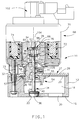
- FIG. 1 there is shown an exhaust gas recirculation valve assembly 10 for use in controlling the recirculation of exhaust gas in an internal combustion engine.
- the assembly 10 comprises a base 12, shown in detail in Figure 2, having upper and lower surfaces 14 and 16 respectively.
- An exhaust chamber 18 is formed in base 12, with an inlet opening 20 and an outlet opening 22 disposed therein.
- a valve seat 24 surrounds exhaust opening 22, although in an alternate embodiment the valve seat may be placed around inlet opening 20.
- a bearing recess 26 is formed in base 12, generally in alignment with valve seat 24.
- the base 12 be constructed as a single piece, powder metal part with the outlet opening 22, the valve seat 24, and the bearing recess 26 formed in the same powder metal tooling. Such a construction technique generally eliminates misalignment between the valve seat 24 and the bearing recess 26 which would occur if these elements were machined in separate operations.
- the cover assembly 27 has an opening 30 extending therethrough in general alignment with valve seat 24 and one or more support spacers 32 extending outwardly from cover 28.
- the spacers provide support for an actuator 68, described in further detail below.
- a valve assembly 34 is disposed within base 12.
- the valve assembly 34 comprises a valve member 36 mounted by valve seat 24 and a valve stem 38 having a first end 40 from which valve member 36 extends, a central portion 42 extending outwardly from exhaust chamber 18 through opening 30 in cover assembly 27, and a second end 44 for engagement with actuator 68.
- Second end 44 is stepped, with a first, reduced diameter portion 46 extending axially from second end 44 to terminate at shoulder 48, and a second reduced diameter portion 50, having a diameter less than that of the first reduced portion 46, which is adjacent to and extends axially from second end 44 by a distance less than the first reduced portion, to terminate at shoulder 52.
- a one-piece bearing 54 aligns valve member 36 with valve seat 24.
- the bearing 54 comprises a lower bearing portion 55 having an aperture 56 extending therethrough in coaxial alignment with valve seat 24, which is configured to guide valve stem 38 in a sliding relationship therewith.
- positioning means such as flange 57 which engage bearing recess 26 to position bearing 54 in precise alignment with valve seat 24.
- the bearing 54 is constructed in a powder metal process with a pin in the powder pressing machine used to produce bearing apertures 56, 61 and 62. This process allows very precise aperture positioning and a high degree of accuracy with respect to locating the bearing positioning flange 57 because the entire part is formed at the same time and in the same tool.
- Leakage of exhaust gas out of exhaust chamber 18 between the valve stem 38 and the lower bearing portion 55 is undesirable due to the release of untreated exhaust gas to the atmosphere and also because of the detrimental effect soot and other contaminants have on the performance and durability of the bearing 54 and actuator 68.
- Actuator 68 is disposed at the second end 44 of valve assembly 34 to operate valve member 36 into and out of engagement with valve seat 24, thereby allowing exhaust gas to flow out of exhaust chamber 18.
- Actuator 68 comprises a housing 70 fixedly supported in spaced relationship to base 12 by spacers 32 and support screws 33.
- a coil assembly 72 is mounted within housing 70 with a non-magnetic armature sleeve 74 disposed in a hollow cylindrical central portion thereof.
- An armature core 76 is mounted within sleeve 74 for reciprocal motion relative to sleeve 74, coil assembly 72, and housing 70.
- Armature core 76 has an axially extending hollow central portion 78 in coaxial alignment with valve seat 24, and into which valve stem 38 extends.
- a central web 80 having upper and lower surfaces 82 and 84 respectively, extends laterally across hollow central portion 78.
- Web 80 has a thickness in the axial direction which is less than the axial length of the first reduced portion 46 of valve stem end 44.
- an axially extending opening 86 having a diameter greater than that of the first reduced portion 46 of valve stem end 44 is formed in web 80.
- valve stem end 44 extends through opening 86 in web 80 with space extending, in the lateral direction, on either side of the valve end 44, thereby providing room for relative movement between armature core 76 and valve assembly 34.
- This lateral movement facilitates the precise coaxial alignment of the valve stem 38 relative to valve seat 24 by the bearing 54. Binding of the stem 38 may occur without provision for such movement since precise alignment of the valve assembly 34 and the actuator 68 is difficult to maintain due to the many components involved in positioning the armature core 76.
- a valve stem support assembly comprising a lower armature support disc 90 having a central opening 92 which substantially corresponds to the diameter of the first reduced portion 46 of valve stem end 44.
- the support disc is placed over the end 44 of valve stem 38 where it rests against shoulder 48 in a supporting relationship to the lower surface 84 of central web 80.
- an upper armature support disc 94 has a central opening 96 which substantially corresponds to the diameter of the second reduced portion 50 of valve stem end 44.
- the upper armature support disc 94 rests against shoulder 52 of valve stem end 44 in a face-to-face relationship with the upper surface 82 of central web portion 80.
- a recess 98 formed in the upper surface of upper support disc 94 allows the end of second reduced portion 50 of valve stem end 44 to be spun down, into the recess to secure valve assembly 34 to armature core 76.
- armature biasing means such as spring washer 100 may be disposed between lower support disc 90 and the lower surface 84 of web 80.
- valve stem support assembly 88 The components of the valve stem support assembly 88 are chosen to be of a size which allows lateral movement between the assembly and the inner wall of hollow portion 78 of armature core 76. As a result, during operation, armature core 76 is capable of lateral movement relative to valve stem end 44 due to the space provided within opening 86.
- armature biasing means such as a spring washer 100 may be disposed between one of the armature support discs 90, 94 and the armature web 80.
- the spring washer 100 is preferably disposed between lower support disc 90 and armature web lower surface 82 so that armature 76 moves against a solid disc 94 when opening valve 36, thereby maximizing response time and durability.
- Vent passages 106 extend axially through web portion 80. The passages prevent a pressure or vacuum condition from occurring on either side of the armature core 76 during reciprocal movement, which would affect response time of the EGR valve.
- armature core seal 108 closes the central opening in coil assembly 72 in which armature core 76 is disposed. Armature core seal 108 has an opening formed therein through which valve assembly 34 passes. Additionally, core seal 108 is held in position by compression spring 109 which extends between the seal and the cover assembly 27, as shown in Figure 1.
- a valve position sensor 102 is mounted to the top of housing 70 and has a follower 104 which is axially aligned with and extends into the hollow portion 78 of armature core 76 to engage the upper support disc 94.
- follower 104 is biased against the armature core 76 by a return spring (not shown) which acts to move the armature and valve assembly axially to seat valve member 36 within valve seat 24 when the actuator is not in operation.
- the exhaust gas recirculation valve assembly described above can provide a bearing member which allows precise alignment of the valve with the valve seat, thereby minimizing leakage past the valve member and assuring accurate metering of exhaust gas recirculation.
- the bearing member is configured to minimize impingement of any escaping exhaust gas on the valve actuator by disrupting gas flow along the surface of valve stem 38, thereby directing the gas away from actuator 68.
Landscapes
- Engineering & Computer Science (AREA)
- Chemical & Material Sciences (AREA)
- Combustion & Propulsion (AREA)
- Mechanical Engineering (AREA)
- General Engineering & Computer Science (AREA)
- Exhaust-Gas Circulating Devices (AREA)
- Lift Valve (AREA)
Applications Claiming Priority (2)
| Application Number | Priority Date | Filing Date | Title |
|---|---|---|---|
| US07/802,803 US5129623A (en) | 1991-12-06 | 1991-12-06 | Linear EGR tri-bearing |
| US802803 | 1991-12-06 |
Publications (2)
| Publication Number | Publication Date |
|---|---|
| EP0545455A1 true EP0545455A1 (fr) | 1993-06-09 |
| EP0545455B1 EP0545455B1 (fr) | 1995-08-09 |
Family
ID=25184746
Family Applications (1)
| Application Number | Title | Priority Date | Filing Date |
|---|---|---|---|
| EP92203504A Expired - Lifetime EP0545455B1 (fr) | 1991-12-06 | 1992-11-16 | Ensemble de valve de recirculation de gaz d'échappement |
Country Status (4)
| Country | Link |
|---|---|
| US (1) | US5129623A (fr) |
| EP (1) | EP0545455B1 (fr) |
| CA (1) | CA2072819C (fr) |
| DE (1) | DE69204031T2 (fr) |
Cited By (1)
| Publication number | Priority date | Publication date | Assignee | Title |
|---|---|---|---|---|
| WO1995027134A1 (fr) * | 1994-03-31 | 1995-10-12 | Siemens Electric Limited | Systeme de recyclage de gaz d'echappement a soupape de recyclage a action rapide |
Families Citing this family (17)
| Publication number | Priority date | Publication date | Assignee | Title |
|---|---|---|---|---|
| US5203830A (en) * | 1992-06-01 | 1993-04-20 | Caterpillar Inc. | Method and apparatus to reduce engine combustion noise utilizing unit valve actuation |
| JP3546469B2 (ja) * | 1994-06-03 | 2004-07-28 | 三菱電機株式会社 | 流量弁制御装置 |
| JP3068746B2 (ja) * | 1994-06-17 | 2000-07-24 | 三菱電機株式会社 | 電動式流量制御弁 |
| US5593132A (en) * | 1995-06-30 | 1997-01-14 | Siemens Electric Limited | Electromagnetic actuator arrangement for engine control valve |
| EP0851977B1 (fr) * | 1995-08-29 | 1999-10-27 | Siemens Canada Limited | Nouvelle construction pour parties non mobile d'une soupape electrique de recirculation des gaz d'echappement |
| US5588414A (en) * | 1995-08-29 | 1996-12-31 | Siemens Electric Limited | Construction for maintaining assembled axial integrity of an electrically actuated valve |
| US5911401A (en) * | 1995-08-29 | 1999-06-15 | Siemens Electric Limited | Electric actuated exhaust gas recirculation valve |
| US5707039A (en) * | 1996-04-08 | 1998-01-13 | General Motors Corporation | Hydraulic solenoid control valve |
| US5878779A (en) * | 1996-08-29 | 1999-03-09 | General Motors Corporation | Actuator housing |
| US5687698A (en) * | 1996-08-29 | 1997-11-18 | General Motors Corporation | Exhaust gas recirculation valve |
| US5901690A (en) * | 1997-09-03 | 1999-05-11 | Siemens Canada Limited | Electromagnetic actuated exhaust gas recirculation valve |
| JP3709277B2 (ja) * | 1997-11-12 | 2005-10-26 | 株式会社ケーヒン | バルブの駆動部と弁軸との連結構造 |
| US6439213B2 (en) * | 2000-02-24 | 2002-08-27 | Delphi Technologies, Inc. | Shaft leakage arresting system for a gas management valve |
| US20020129801A1 (en) * | 2001-03-16 | 2002-09-19 | Smith Craig D. | Short-stroke valve assembly for modulated pulsewidth flow control |
| US20040051067A1 (en) * | 2002-09-12 | 2004-03-18 | Fujita Mahoro M. | Pressurized valve actuator |
| JP5988853B2 (ja) * | 2012-12-07 | 2016-09-07 | 愛三工業株式会社 | 排気還流バルブ |
| ITUA20164688A1 (it) * | 2016-06-27 | 2017-12-27 | Magneti Marelli Spa | Dispositivo attuatore di valvola di ricircolo dei gas di scarico (egr) in un motore endotermico e relativo gruppo valvola di ricircolo dei gas di scarico |
Citations (1)
| Publication number | Priority date | Publication date | Assignee | Title |
|---|---|---|---|---|
| EP0428274A1 (fr) * | 1989-11-13 | 1991-05-22 | General Motors Corporation | Vanne de recirculation des gaz d'échappement |
Family Cites Families (7)
| Publication number | Priority date | Publication date | Assignee | Title |
|---|---|---|---|---|
| US2448717A (en) * | 1945-05-01 | 1948-09-07 | Morris Machine Works | Sealing means for pumping apparatus |
| US4262690A (en) * | 1979-08-30 | 1981-04-21 | Acf Industries, Incorporated | High pressure stem packing for gate valves |
| AU591733B2 (en) * | 1985-12-26 | 1989-12-14 | Jidosha Kiki Co. Ltd. | Exhaust gas brake system |
| US4725040A (en) * | 1986-02-28 | 1988-02-16 | General Motors Corporation | Exhaust gas recirculation valve assembly |
| US4881829A (en) * | 1986-06-30 | 1989-11-21 | Koelsch Lester M | Submersible bearing assembly |
| US4782811A (en) * | 1987-03-30 | 1988-11-08 | Robertshaw Controls Company | Exhaust gas recirculation valve construction and method of making the same |
| FI81453C (fi) * | 1988-06-22 | 1990-10-10 | Outokumpu Oy | Analysatortaetning. |
-
1991
- 1991-12-06 US US07/802,803 patent/US5129623A/en not_active Expired - Fee Related
-
1992
- 1992-06-30 CA CA002072819A patent/CA2072819C/fr not_active Expired - Fee Related
- 1992-11-16 DE DE69204031T patent/DE69204031T2/de not_active Expired - Fee Related
- 1992-11-16 EP EP92203504A patent/EP0545455B1/fr not_active Expired - Lifetime
Patent Citations (1)
| Publication number | Priority date | Publication date | Assignee | Title |
|---|---|---|---|---|
| EP0428274A1 (fr) * | 1989-11-13 | 1991-05-22 | General Motors Corporation | Vanne de recirculation des gaz d'échappement |
Non-Patent Citations (2)
| Title |
|---|
| PATENT ABSTRACTS OF JAPAN vol. 016, no. 426 (M-1306)8 September 1992 & JP-A-04 143450 ( MITSUBISHI ) 18 May 1992 * |
| PATENT ABSTRACTS OF JAPAN vol. 7, no. 79 (M-204)(1224) 31 March 1983 & JP-A-58 005460 ( SANWA SEIKI ) 12 January 1983 * |
Cited By (1)
| Publication number | Priority date | Publication date | Assignee | Title |
|---|---|---|---|---|
| WO1995027134A1 (fr) * | 1994-03-31 | 1995-10-12 | Siemens Electric Limited | Systeme de recyclage de gaz d'echappement a soupape de recyclage a action rapide |
Also Published As
| Publication number | Publication date |
|---|---|
| CA2072819A1 (fr) | 1993-06-07 |
| DE69204031T2 (de) | 1996-01-11 |
| US5129623A (en) | 1992-07-14 |
| EP0545455B1 (fr) | 1995-08-09 |
| DE69204031D1 (de) | 1995-09-14 |
| CA2072819C (fr) | 1996-10-29 |
Similar Documents
| Publication | Publication Date | Title |
|---|---|---|
| EP0428274B1 (fr) | Vanne de recirculation des gaz d'échappement | |
| EP0545455B1 (fr) | Ensemble de valve de recirculation de gaz d'échappement | |
| EP0701055B1 (fr) | Actionneur pour soupape de recirculation de gaz d'échappement | |
| US5020505A (en) | Exhaust gas recirculation valve assembly | |
| EP0701053B1 (fr) | Actionneur pour soupape de recirculation de gaz d'échappement | |
| DE60002627T2 (de) | Elektromagnetisch betätigtes Abgasrückführungsventil | |
| EP0701054A2 (fr) | Actionneur à déplacement linéaire à solenoide pour une soupape de recirculations de gaz d'échappement | |
| US4771984A (en) | Electromagnetically actuatable fuel-injection valve | |
| KR900001391B1 (ko) | 배출개스 재순환 밸브장치 | |
| JP2635428B2 (ja) | 電磁操作装置 | |
| EP0117603B1 (fr) | Soupape d'injection de carburant | |
| EP1019626B1 (fr) | Soupape de recirculation de gaz d'echappement a solenoide centre et mecanisme de soupape flottante | |
| CA2112281C (fr) | Vanne electromagnetique avec collecteur d'impuretes | |
| US6715475B2 (en) | Exhaust gas recirculation valve | |
| US20080190404A1 (en) | Internal Combustion Engine Having Exhaust Gas Recirculation | |
| EP0990826B1 (fr) | Vanne de regulation | |
| US6422223B2 (en) | Electromechanically actuated solenoid exhaust gas recirculation valve | |
| US4350136A (en) | Exhaust gas recirculation valve | |
| EP1300578B1 (fr) | Soupape de commande des émissions et actionnée électromagnétiquement ayant un pièce de pôle biconique | |
| EP0481608A1 (fr) | Injecteur électronique de carburant | |
| EP1130244B1 (fr) | Sous-ensemble de valve de re-circulation de gaz d'échappement et arrête-gaz | |
| JP3733597B2 (ja) | 排気ガス還流装置 |
Legal Events
| Date | Code | Title | Description |
|---|---|---|---|
| PUAI | Public reference made under article 153(3) epc to a published international application that has entered the european phase |
Free format text: ORIGINAL CODE: 0009012 |
|
| AK | Designated contracting states |
Kind code of ref document: A1 Designated state(s): DE FR GB IT |
|
| 17P | Request for examination filed |
Effective date: 19930628 |
|
| 17Q | First examination report despatched |
Effective date: 19940110 |
|
| GRAA | (expected) grant |
Free format text: ORIGINAL CODE: 0009210 |
|
| ITF | It: translation for a ep patent filed | ||
| AK | Designated contracting states |
Kind code of ref document: B1 Designated state(s): DE FR GB IT |
|
| REF | Corresponds to: |
Ref document number: 69204031 Country of ref document: DE Date of ref document: 19950914 |
|
| ET | Fr: translation filed | ||
| PLBE | No opposition filed within time limit |
Free format text: ORIGINAL CODE: 0009261 |
|
| 26N | No opposition filed | ||
| REG | Reference to a national code |
Ref country code: GB Ref legal event code: IF02 |
|
| PGFP | Annual fee paid to national office [announced via postgrant information from national office to epo] |
Ref country code: GB Payment date: 20021108 Year of fee payment: 11 |
|
| PGFP | Annual fee paid to national office [announced via postgrant information from national office to epo] |
Ref country code: FR Payment date: 20021115 Year of fee payment: 11 |
|
| PGFP | Annual fee paid to national office [announced via postgrant information from national office to epo] |
Ref country code: DE Payment date: 20021227 Year of fee payment: 11 |
|
| PG25 | Lapsed in a contracting state [announced via postgrant information from national office to epo] |
Ref country code: GB Free format text: LAPSE BECAUSE OF NON-PAYMENT OF DUE FEES Effective date: 20031116 |
|
| PG25 | Lapsed in a contracting state [announced via postgrant information from national office to epo] |
Ref country code: DE Free format text: LAPSE BECAUSE OF NON-PAYMENT OF DUE FEES Effective date: 20040602 |
|
| GBPC | Gb: european patent ceased through non-payment of renewal fee |
Effective date: 20031116 |
|
| PG25 | Lapsed in a contracting state [announced via postgrant information from national office to epo] |
Ref country code: FR Free format text: LAPSE BECAUSE OF NON-PAYMENT OF DUE FEES Effective date: 20040730 |
|
| REG | Reference to a national code |
Ref country code: FR Ref legal event code: ST |
|
| PG25 | Lapsed in a contracting state [announced via postgrant information from national office to epo] |
Ref country code: IT Free format text: LAPSE BECAUSE OF NON-PAYMENT OF DUE FEES Effective date: 20051116 |