EP0545458A1 - Method and apparatus for the matting of light-sensitive printing plates - Google Patents
Method and apparatus for the matting of light-sensitive printing plates Download PDFInfo
- Publication number
- EP0545458A1 EP0545458A1 EP92203537A EP92203537A EP0545458A1 EP 0545458 A1 EP0545458 A1 EP 0545458A1 EP 92203537 A EP92203537 A EP 92203537A EP 92203537 A EP92203537 A EP 92203537A EP 0545458 A1 EP0545458 A1 EP 0545458A1
- Authority
- EP
- European Patent Office
- Prior art keywords
- light
- droplets
- sensitive layer
- printing plate
- bowl
- Prior art date
- Legal status (The legal status is an assumption and is not a legal conclusion. Google has not performed a legal analysis and makes no representation as to the accuracy of the status listed.)
- Withdrawn
Links
Images

Classifications
-
- G—PHYSICS
- G03—PHOTOGRAPHY; CINEMATOGRAPHY; ANALOGOUS TECHNIQUES USING WAVES OTHER THAN OPTICAL WAVES; ELECTROGRAPHY; HOLOGRAPHY
- G03F—PHOTOMECHANICAL PRODUCTION OF TEXTURED OR PATTERNED SURFACES, e.g. FOR PRINTING, FOR PROCESSING OF SEMICONDUCTOR DEVICES; MATERIALS THEREFOR; ORIGINALS THEREFOR; APPARATUS SPECIALLY ADAPTED THEREFOR
- G03F7/00—Photomechanical, e.g. photolithographic, production of textured or patterned surfaces, e.g. printing surfaces; Materials therefor, e.g. comprising photoresists; Apparatus specially adapted therefor
- G03F7/004—Photosensitive materials
- G03F7/09—Photosensitive materials characterised by structural details, e.g. supports, auxiliary layers
- G03F7/115—Photosensitive materials characterised by structural details, e.g. supports, auxiliary layers having supports or layers with means for obtaining a screen effect or for obtaining better contact in vacuum printing
-
- B—PERFORMING OPERATIONS; TRANSPORTING
- B05—SPRAYING OR ATOMISING IN GENERAL; APPLYING FLUENT MATERIALS TO SURFACES, IN GENERAL
- B05B—SPRAYING APPARATUS; ATOMISING APPARATUS; NOZZLES
- B05B5/00—Electrostatic spraying apparatus; Spraying apparatus with means for charging the spray electrically; Apparatus for spraying liquids or other fluent materials by other electric means
- B05B5/025—Discharge apparatus, e.g. electrostatic spray guns
- B05B5/04—Discharge apparatus, e.g. electrostatic spray guns characterised by having rotary outlet or deflecting elements, i.e. spraying being also effected by centrifugal forces
-
- B—PERFORMING OPERATIONS; TRANSPORTING
- B05—SPRAYING OR ATOMISING IN GENERAL; APPLYING FLUENT MATERIALS TO SURFACES, IN GENERAL
- B05B—SPRAYING APPARATUS; ATOMISING APPARATUS; NOZZLES
- B05B5/00—Electrostatic spraying apparatus; Spraying apparatus with means for charging the spray electrically; Apparatus for spraying liquids or other fluent materials by other electric means
- B05B5/001—Electrostatic spraying apparatus; Spraying apparatus with means for charging the spray electrically; Apparatus for spraying liquids or other fluent materials by other electric means incorporating means for heating or cooling, e.g. the material to be sprayed
Definitions
- the present invention relates to a method and apparatus for the matting of tight-sensitive printing plates.
- the surface of the light-sensitive layer has small protrusions which prevents the original film from adhering sealingly to the surface of the light-sensitive layer.
- the treatment which produces such small protrusions is called matting.
- the English patent No. 1,495,361 teaches the accomplishment of matting by applying over the light-sensitive layer a coating of a light transparent resin, soluble in the development solution, containing solid particles having an average diameter of 2-40 microns.
- This method has the disadvantage that the solid particles removed by the development bath accumulate in the automatic development apparatus, and make it difficult their maintenance.
- the English patent No. 1,512,080 intends to overcome this drawback by accomplishing matting with a layer of viscous resin applied with a roller having a rough surface.
- the viscosity of the resin used should be such that the irregularities created by the roller remain unaltered until the layer of matting has dried.
- the English patent No. 1,542,131 relates to a similar solution, except that the matting layer may also comprise solid particles, as in the process disclosed by the English patent No. 1,495,361.
- An object of the present invention is to provide a method for applying, in a simple and effective manner, over the light-sensitive layer of a light-sensitive plate, a matting layer made of compounds which are easily soluble in the development bath.
- Another object of the invention is to provide an apparatus which allows said method to be carried out in a simple and quick manner.
- the method of this invention for applying a matting layer over the light-sensitive layer of a printing plate comprising a support and a light-sensitive layer is characterized in that (i) over said light-sensitive layer there is sprayed a beam of finely-divided droplets of a low-viscosity composition comprising at least a solvent and at least a compound suitable for matting and easily soluble in a development bath, and (ii) the spraying step is performed under such conditions that a large part of said solvent evaporates before said droplets reach said light-sensitive layer, so that said droplets are very viscous when they reach said light-sensitive layer, adhere to it, and dry quickly, thus forming minuscule protrusions.
- said printing plate is made to slide while performing said spraying step. Even more preferably a pre-set electrical charge is supplied to said beam of finely-divided droplets.
- the apparatus according to the invention for applying a matting layer over the light-sensitive layer of a printing plate comprising a support and a light-sensitive layer, is characterized in that it comprises
- said apparatus is also characterized in that it comprises guide means for making said printing plate to slide while said spraying step is performed, and also means capable of delivering a pre-selected electrical charge to said beam of finely-divided droplets.
- said spraying means comprise in turn
- said apparatus comprises means suitable to form, around said beam of finely-divided droplets, an air cone capable of containing said beam externally, and said printing plate has a temperature of from 40°C to 60°C.
- said composition comprising at least a solvent and at least a compound suitable for matting, has a low viscosity before it is sprayed, while, due to the evaporation of the solvent, it becomes highly viscous when it reaches the surface of said printing plate, so that it adheres to plate itself and dries quickly, thus forming minuscule protrusions.
- substances suitable for matting are polyacrylic acid, polyacrylamide, polyvinylpyrrolidone, soluble amides, soluble co-polymers of polyvinylacetate and crotonic acid, polyvinyl acid, soluble carboxy-methyl cellulose, hydroxy-methyl cellulose soluble polymers of maleic anhydride and vinylether, and the like.
- solvents suitable for the matting composition of this invention are water, lower aliphatic alcohols and aqueous ammmonia (ammonium hydroxide).
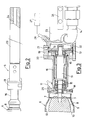
- Fig. 1 shows a strip of a light-sensitive printing plate 1 comprising a support made of aluminium or an alloy thereof, and a light-sensitive layer made of a suitable known composition.
- the strip that is kept at a temperature of about 50°C, moves at a pre-selected speed, preferably at, 8-10 m/min, in the direction of the arrows 3; there are indicated with 2 the strip's guide rollers, assembled idle in a supporting structure, indicated as a whole with 4, that is placed in a forced-suction chamber, which is not shown.
- a spraying unit 5 is capable of directing on the printing plate 1 a beam of finely-divided droplets of a low-viscosity composition, having a preferred viscosity of from 2 to 10 centipoises.
- the unit 5 comprises an atomization bowl, indicated as a whole with 6, provided with an external shaped wall 8, with internal shaped walls 9 and 10 and with a crown of holes 7 having a pre-selected size; the bowl 6 is made to rotate by a shaft 11 integral with a turbine motor 12, operated by a flow of compressed air at a pre-selected pressure, supplied by jets 13; there is indicated with 14 the discharge line of the air operating the turbine motor 10.
- the shaft 11 is rotatably supported, by means of ball bearings 15, in a tubular casing 16, in which there is a nozzle 17 capable of delivering in the bowl 6 said low-viscosity composition, supplied at a pre-selected rate by a volumetric pump, which is not shown; in the tubular casing 16 there is a distributor 18 that conveys a flow of additional compressed air on the external wall 8 of the bowl 6, forming an air cone which contains said beam of finely-divided droplets externally, allowing it to be opened or closed, in order to vary the surface covered by the beam and thus to cover strips of different dimensions, while keeping the position of the spraying unit 5 fixed.
- the tubular casing 16 is provided with a flange 19, in which the turbine motor 12 is contained, provided with threaded holes 20 and 21 to which there are connected the fittings of the lines of compressed air delivered to the turbine 12 and to the distributor 18; the flange 19 is fastened, by means of bolts 22 to an insulating casing 23 of an electrode 24, which is connected to the positive pole of a source of electrical energy, which is not shown, and is operationally connected to the nozzle 17 by means of a pin, which is not shown, screwed into the hole 25; the printing plate 1 is charged negatively, since it is connected to ground.
- an optical detector capable of reading the rate of rotation of the turbine motor 12, operatively connected to a control unit, indicated by the block 27; the control unit 27 controls the delivery of compressed air through the jets 13, to maintain the rate of rotation of the turbine motor 12 and of the spraying cone 6, at a constant pre-selected value suitable for breaking up into finely-divided droplets said composition delivered by the nozzle 17.
- the spraying unit 5 is placed at a pre-selected distance from the printing plate 1, preferably at about 450 mm, and is inclined at a pre-selected angle, preferably of about 30°, with respect to a line orthogonal to said printing plate 1. Due to evaporation of a large part of the solvent, the finely-divided droplets are very viscous, when they come into contact with the light-sensitive layer of said plate 1 and drying is quickly completed, due to the heat absorbed from the plate 1.
- a preferred range of viscosity of the droplets when they reach the light-sensitive layer is of from 3000 to 6000 centipoises.
- low-viscosity matting composition is as follows Water 100 parts in weight Ethanol 8 Tecol V 24 (polyacrylic acid) 10 Ammonia 6 Pluronic (BASF; surface-active, copolymer of ethylene and propylene oxide) 0.05
- the atomization bowl 6, receives from the nozzle 17 a pre-selected delivery of said low-viscosity matting composition, and, by rotation, atomizes it through the holes 7, forming a beam of finely-divided droplets, charged positively by the electrode 24.
- the beam of droplets, contained externally by the air cone formed by the wall 8 of the atomization bowl 6, is attracted by the printing plate 1, charged negatively, and is deposited on it in the amount of 40-60x103 droplets per square centimeter; said droplets are very viscous (about 4000 centipoises) due to the evaporation of a large part of the solvent, when they come into contact with the light-sensitive layer of said plate 1.
- the delivery of said low-viscosity matting composition through the nozzle 17 is adjusted by said volumetric pump, while the atomization of the composition is adjusted through the speed of rotation of the atomization bowl 6, by varying the pressure of the air driving the turbine motor 12; at a low pressure, of 0.5 atm, comparatively larger and more viscous droplets are obtained, while with a high pressure, of 3.5 atm, very fine and less viscous droplets are obtained; the rotation speed of the atomization bowl 6 is preferably of 30,000 rpm, in order to obtain droplets having an average size of 2-4 micron and a viscosity of about 4000 centipoise, when they come into contact with the light-sensitive layer of the plate 1.
- the detector 26 and the control unit 27 control any variations in the speed of the atomization bowl 6 with respect to the pre-set value, due to possible deposits that accumulate in the atomization bowl 6.
- the attraction of the droplets toward the printing plate 1 varies with the electrostatic tension provided by the electrode 24; while a low tension, such as for example of 30 KV, is hardly effective, a high tension, such as for example of 80 KV, also thrusts toward the plate 1 droplets which are too large, thus causing its pricking, that is, the etching of the light-sensitive layer; the electrostatic tension of the electrode 24 is preferably of 50 KV.
- the inclination of the unit 5 with respect to the plate 1 is selected in such a way that the force of gravity predominates over the electrostatic attraction in the case of the droplets which are too large and makes them fall to the ground while the smaller droplets are electrostatically attracted on the layer 1.
Landscapes
- Engineering & Computer Science (AREA)
- Architecture (AREA)
- Structural Engineering (AREA)
- Physics & Mathematics (AREA)
- General Physics & Mathematics (AREA)
- Manufacture Or Reproduction Of Printing Formes (AREA)
- Exposure And Positioning Against Photoresist Photosensitive Materials (AREA)
- Application Of Or Painting With Fluid Materials (AREA)
Applications Claiming Priority (2)
| Application Number | Priority Date | Filing Date | Title |
|---|---|---|---|
| ITMI913186 | 1991-11-28 | ||
| ITMI913186A IT1252016B (it) | 1991-11-28 | 1991-11-28 | Metodo ed apparecchiatura per la mattatura di lastre da stampa fotosensibili |
Publications (1)
| Publication Number | Publication Date |
|---|---|
| EP0545458A1 true EP0545458A1 (en) | 1993-06-09 |
Family
ID=11361210
Family Applications (1)
| Application Number | Title | Priority Date | Filing Date |
|---|---|---|---|
| EP92203537A Withdrawn EP0545458A1 (en) | 1991-11-28 | 1992-11-18 | Method and apparatus for the matting of light-sensitive printing plates |
Country Status (2)
| Country | Link |
|---|---|
| EP (1) | EP0545458A1 (it) |
| IT (1) | IT1252016B (it) |
Cited By (2)
| Publication number | Priority date | Publication date | Assignee | Title |
|---|---|---|---|---|
| EP0848297A3 (en) * | 1996-12-11 | 2000-01-12 | Konica Corporation | Method for producing a presensitized printing plate |
| US6500494B2 (en) | 2000-12-29 | 2002-12-31 | Kodak Polychrome Graphics Llc | Spray coating matting method for printing plate precursors |
Citations (3)
| Publication number | Priority date | Publication date | Assignee | Title |
|---|---|---|---|---|
| FR2521314A1 (fr) * | 1982-02-10 | 1983-08-12 | Fuji Photo Film Co Ltd | Procede de matage d'un materiau d'enregistrement |
| EP0344985A2 (en) * | 1988-06-03 | 1989-12-06 | E.I. Du Pont De Nemours And Company | Radiation sensitive devices |
| EP0429234A2 (en) * | 1989-11-21 | 1991-05-29 | Du Pont (UK) Limited | Improvements in or relating to radiation sensitive devices |
-
1991
- 1991-11-28 IT ITMI913186A patent/IT1252016B/it active IP Right Grant
-
1992
- 1992-11-18 EP EP92203537A patent/EP0545458A1/en not_active Withdrawn
Patent Citations (3)
| Publication number | Priority date | Publication date | Assignee | Title |
|---|---|---|---|---|
| FR2521314A1 (fr) * | 1982-02-10 | 1983-08-12 | Fuji Photo Film Co Ltd | Procede de matage d'un materiau d'enregistrement |
| EP0344985A2 (en) * | 1988-06-03 | 1989-12-06 | E.I. Du Pont De Nemours And Company | Radiation sensitive devices |
| EP0429234A2 (en) * | 1989-11-21 | 1991-05-29 | Du Pont (UK) Limited | Improvements in or relating to radiation sensitive devices |
Cited By (3)
| Publication number | Priority date | Publication date | Assignee | Title |
|---|---|---|---|---|
| EP0848297A3 (en) * | 1996-12-11 | 2000-01-12 | Konica Corporation | Method for producing a presensitized printing plate |
| US6500494B2 (en) | 2000-12-29 | 2002-12-31 | Kodak Polychrome Graphics Llc | Spray coating matting method for printing plate precursors |
| WO2002054152A3 (en) * | 2000-12-29 | 2003-02-06 | Kodak Polychrome Graphics Co | Spray coating matting method for printing plate precursors |
Also Published As
| Publication number | Publication date |
|---|---|
| ITMI913186A1 (it) | 1993-05-28 |
| IT1252016B (it) | 1995-05-27 |
| ITMI913186A0 (it) | 1991-11-28 |
Similar Documents
| Publication | Publication Date | Title |
|---|---|---|
| US4781941A (en) | Method of matting pre-sensitized plates | |
| CA1331086C (en) | Process and machine for electrostatic coating | |
| US5162193A (en) | Radiation sensitive devices | |
| US20030197311A1 (en) | Process and apparatus for forming a thin-walled elastomeric article | |
| JPH08153669A (ja) | 薄膜形成方法及び形成装置 | |
| JPH05208163A (ja) | スピン・コーティング装置および方法 | |
| US5006442A (en) | Method of forming a discontinuous covering layer on radiation sensitive devices | |
| EP0545458A1 (en) | Method and apparatus for the matting of light-sensitive printing plates | |
| JPH0372350B2 (it) | ||
| JP2812755B2 (ja) | 円筒状塗布体の製造方法 | |
| JPH08167551A (ja) | 薄膜塗布装置 | |
| JP2822603B2 (ja) | 浸漬塗布装置 | |
| JP3064524B2 (ja) | 浸漬塗布装置 | |
| JPH02229562A (ja) | 液体又は溶融体の粒子の生成塗布方法 | |
| JP2005177707A (ja) | 塗工ノズル清浄装置 | |
| JP3707574B2 (ja) | セラミックグリーンシートの製造方法および装置 | |
| JP3903568B2 (ja) | 塗工装置 | |
| JP2844784B2 (ja) | 浸漬塗布装置 | |
| JPH03193160A (ja) | 薄層塗膜の連続形成方法 | |
| EP1352296A2 (en) | Spray coating matting method for printing plate precursors | |
| JP2781868B2 (ja) | 粉体の塗布方法及びその装置 | |
| JP3424026B2 (ja) | 静電塗装機の水溶性塗料供給装置 | |
| CN121339468A (zh) | 一种基于阵列化喷头和轮廓检测的曲面共形电喷雾方法及系统 | |
| JPH0113575Y2 (it) | ||
| JPH0631851U (ja) | 静電塗装装置 |
Legal Events
| Date | Code | Title | Description |
|---|---|---|---|
| PUAI | Public reference made under article 153(3) epc to a published international application that has entered the european phase |
Free format text: ORIGINAL CODE: 0009012 |
|
| AK | Designated contracting states |
Kind code of ref document: A1 Designated state(s): DE ES FR GB IT NL |
|
| 17P | Request for examination filed |
Effective date: 19930730 |
|
| 18D | Application deemed to be withdrawn |
Effective date: 19950531 |