EP0545473A2 - Loi de contrôle de guidage de tanguage pour TCAS II et symbole d'affichage - Google Patents
Loi de contrôle de guidage de tanguage pour TCAS II et symbole d'affichage Download PDFInfo
- Publication number
- EP0545473A2 EP0545473A2 EP92203644A EP92203644A EP0545473A2 EP 0545473 A2 EP0545473 A2 EP 0545473A2 EP 92203644 A EP92203644 A EP 92203644A EP 92203644 A EP92203644 A EP 92203644A EP 0545473 A2 EP0545473 A2 EP 0545473A2
- Authority
- EP
- European Patent Office
- Prior art keywords
- pitch
- symbol
- airplane
- tcas
- pitch axis
- Prior art date
- Legal status (The legal status is an assumption and is not a legal conclusion. Google has not performed a legal analysis and makes no representation as to the accuracy of the status listed.)
- Granted
Links
Images


Classifications
-
- G—PHYSICS
- G08—SIGNALLING
- G08G—TRAFFIC CONTROL SYSTEMS
- G08G5/00—Traffic control systems for aircraft
- G08G5/20—Arrangements for acquiring, generating, sharing or displaying traffic information
- G08G5/26—Transmission of traffic-related information between aircraft and ground stations
-
- G—PHYSICS
- G01—MEASURING; TESTING
- G01C—MEASURING DISTANCES, LEVELS OR BEARINGS; SURVEYING; NAVIGATION; GYROSCOPIC INSTRUMENTS; PHOTOGRAMMETRY OR VIDEOGRAMMETRY
- G01C23/00—Combined instruments indicating more than one navigational value, e.g. for aircraft; Combined measuring devices for measuring two or more variables of movement, e.g. distance, speed or acceleration
- G01C23/005—Flight directors
-
- G—PHYSICS
- G01—MEASURING; TESTING
- G01S—RADIO DIRECTION-FINDING; RADIO NAVIGATION; DETERMINING DISTANCE OR VELOCITY BY USE OF RADIO WAVES; LOCATING OR PRESENCE-DETECTING BY USE OF THE REFLECTION OR RERADIATION OF RADIO WAVES; ANALOGOUS ARRANGEMENTS USING OTHER WAVES
- G01S13/00—Systems using the reflection or reradiation of radio waves, e.g. radar systems; Analogous systems using reflection or reradiation of waves whose nature or wavelength is irrelevant or unspecified
- G01S13/88—Radar or analogous systems specially adapted for specific applications
- G01S13/93—Radar or analogous systems specially adapted for specific applications for anti-collision purposes
- G01S13/933—Radar or analogous systems specially adapted for specific applications for anti-collision purposes of aircraft or spacecraft
-
- G—PHYSICS
- G05—CONTROLLING; REGULATING
- G05D—SYSTEMS FOR CONTROLLING OR REGULATING NON-ELECTRIC VARIABLES
- G05D1/00—Control of position, course, altitude or attitude of land, water, air or space vehicles, e.g. using automatic pilots
- G05D1/04—Control of altitude or depth
- G05D1/06—Rate of change of altitude or depth
- G05D1/0607—Rate of change of altitude or depth specially adapted for aircraft
- G05D1/0615—Rate of change of altitude or depth specially adapted for aircraft to counteract a perturbation, e.g. gust of wind
- G05D1/0623—Rate of change of altitude or depth specially adapted for aircraft to counteract a perturbation, e.g. gust of wind by acting on the pitch
-
- G—PHYSICS
- G05—CONTROLLING; REGULATING
- G05D—SYSTEMS FOR CONTROLLING OR REGULATING NON-ELECTRIC VARIABLES
- G05D1/00—Control of position, course, altitude or attitude of land, water, air or space vehicles, e.g. using automatic pilots
- G05D1/04—Control of altitude or depth
- G05D1/06—Rate of change of altitude or depth
- G05D1/0607—Rate of change of altitude or depth specially adapted for aircraft
- G05D1/0653—Rate of change of altitude or depth specially adapted for aircraft during a phase of take-off or landing
- G05D1/0676—Rate of change of altitude or depth specially adapted for aircraft during a phase of take-off or landing specially adapted for landing
-
- G—PHYSICS
- G08—SIGNALLING
- G08G—TRAFFIC CONTROL SYSTEMS
- G08G5/00—Traffic control systems for aircraft
- G08G5/20—Arrangements for acquiring, generating, sharing or displaying traffic information
- G08G5/21—Arrangements for acquiring, generating, sharing or displaying traffic information located onboard the aircraft
-
- G—PHYSICS
- G08—SIGNALLING
- G08G—TRAFFIC CONTROL SYSTEMS
- G08G5/00—Traffic control systems for aircraft
- G08G5/20—Arrangements for acquiring, generating, sharing or displaying traffic information
- G08G5/25—Transmission of traffic-related information between aircraft
-
- G—PHYSICS
- G08—SIGNALLING
- G08G—TRAFFIC CONTROL SYSTEMS
- G08G5/00—Traffic control systems for aircraft
- G08G5/80—Anti-collision systems
Definitions
- This invention relates to avionics systems and, more particularly, air traffic alert and collision avoidance systems.
- TCAS air Traffic alert and Collision Avoidance System
- ATC Air Traffic Control
- FAA Federal Aviation Administration
- ATC Air Traffic Control
- TCAS has matured to a level where United States public law now requires that a TCAS be installed on commercial airplanes with more than thirty seats, starting in December of 1990.
- a TCAS-equipped airplane is surrounded by TCAS-protected airspace whose physical dimensions vary as a function of altitude and closure rate, i.e., the rate at which other airplanes are approaching the TCAS-equipped airplane.
- TCAS continuously estimates and updates the flight paths of other airplanes through the interrogation of, and replies from, airborne radar beacon transponders located onboard the other airplanes.
- An airplane whose estimated flight path is projected to penetrate the TCAS-protected airspace is considered a collision threat (intruder) and annunciated to the flight crew of the TCAS-equipped airplane.
- TCAS-protected airspace can be divided into a caution area and a warning area, based on the estimated time to the Closest Point of Approach (CPA). About 40-45 seconds prior to CPA an intruder penetrates the caution area and causes the annunciation of a Traffic Advisory (TA) . If the intruder continues to come closer to the TCAS-equipped airplane, at about 20-25 seconds to CPA, the intruder reaches the warning area, resulting in the annunciation of a Resolution Advisory (RA). Both TAs and RAs are constantly updated and, therefore, provide real time position and advisory information.
- CPA Closest Point of Approach
- TAs and RAs are annunciated both visually and aurally.
- the aural portion consists of voice messages.
- the visual portion of TA and RA annunciators includes a traffic display in the horizontal plane and, for RA annunciators, a resolution display in the vertical plane.
- intruder positions are displayed and, when required, maneuver guidance is given--using shape, color and size cues for different levels of alert--on one or more of the following types of instruments: Electronic Horizontal Situation Indicator (EHSI), Electronic Attitude Director Indicator (EADI), Navigation Display (ND), Primary Flight Display (PFD), designated Weather Radar (WXR) or a modified (liquid crystal) Vertical Speed Indicator (VSI).
- EHSI Electronic Horizontal Situation Indicator
- EADI Electronic Attitude Director Indicator
- ND Navigation Display
- PFD Primary Flight Display
- WXR Weather Radar
- VSI Vertical Speed Indicator
- the flight crew uses the displayed information as an aid to visually locating an intruder and, if necessary, taking action to avoid a collision.
- resolution advisories i.e., RAs
- TCAS II is the second generation of TCAS
- the lighted red arc forms either a corrective advisory, which calls for a change in the vertical speed of the TCAS II-equipped airplane, such that the vertical speed pointer of the VSI moves outside of the red arc, or a preventive advisory, which calls for restricted changes in the vertical speed of the TCAS II-equipped airplane, such that the vertical speed pointer remains outside of the red arc.
- the flight crew of the TCAS II-equipped airplane adjusts the vertical speed (rate of climb or descent) of the airplane in the manner dictated by the nature of the advisory.
- the change in vertical speed changes the flight path of the aircraft in a manner designed to gain sufficient separation from the intruder to eliminate the collision threat.
- existing TCAS II VSI RAs comprise a red arc (also called a red band) on the dial of each pilot's vertical speed indicator (VSI).
- the red arc indicates the region of vertical speed (climb or descent) to avoid.
- a green arc also called a green band
- red arc corrective RAs is used to assist a pilot in determining which direction to maneuver and to suggest a range of vertical speed that is sufficient to avoid the red region without being excessive.
- RAs comprise either an Up Advisory or a Down Advisory.
- An Up Advisory is a red arc that emanates from -6,000 feet per minute (FPM) up to the vertical speed above which a collision threat is eliminated.
- a Down Advisory is a red arc that emanates from +6,000 FPM down to the vertical speed below which a collision threat is eliminated. Up and Down Advisories can occur simultaneously. In this instance two red arcs emanate up from -6,000 FPM and down from +6,000 FPM occur, to leave a region in between that indicates a vertical speed range adequate for traffic separation.
- TCAS II VSI RAs are satisfactory, they have certain disadvantages. They are not integrated into the primary electronic flight instrument systems of airplanes. They display control information on an instrument that is not used by a pilot to extract control information. They require an expensive retrofit for airplanes equipped with conventional VSIs. More importantly, they are not intuitive. More specifically, changing the climb or descent flight path of an airplane involves changing the pitch attitude of the airplane. Because pilots control pitch with reference to the attitude indicator of an airplane rather than the vertical speed indicator, a TCAS RA in the form of a pitch attitude advisory is more useful than is a VSI advisory.
- the present invention is directed to providing a Resolution Advisory (RA) in the form of a pitch guidance symbol on the electronic attitude or primary flight display of an airplane instead of, or in addition to, a conventional TCAS II VSI RA.
- RA Resolution Advisory
- an airplane pitch guidance control law and display symbol for a traffic alert and collision avoidance system (TCAS) is provided.
- the control law converts a TCAS II computer-generated collision avoidance vertical air speed command into a pitch guidance command.
- the pitch guidance command controls the position of a symbol on the pitch axis of an electronic attitude display that identifies the climb or descent pitch attitudes available to achieve a climb or descent flight path angle that eliminates a collision threat.
- the preferred symbol includes a horizontal leg and a pair of outwardly extending legs.
- the horizontal or pitch axis leg defines the minimum climb or descent attitude required to achieve a safe climb or descent angle.
- the pitch axis leg and the outwardly extending legs combine to define a climb or descent pitch angle range to avoid.
- the pitch axis leg and the outwardly extending legs combine to define a safe climb or descent pitch angle range.
- the outwardly extending legs converge in a direction that augments the pitch up (or pitch down) information provided by the horizontal (pitch axis) leg.
- the TCAS II computer-generated collision avoidance vertical speed command (V STCAS ) is subtractively summed with the vertical speed of the TCAS-equipped airplane.
- the result of the subtraction is multiplied by a sensitivity factor whose value is dependent upon the true air speed of the aircraft and a value (57.3) that approximates the arc tangent of the quotient.
- the result of the multiplication is combined with the pitch attitude of the aircraft.
- the pitch attitude of the aircraft is filtered by a second order filter prior to being summed with the sensitivity compensated difference between the TCAS commanded vertical air speed and the actual vertical air speed of the TCAS-equipped airplane.
- the time constant of the filter is chosen such that the filter compensates for the fact that a change in flight path angle lags a change in pitch attitude.
- the invention provides a way of equipping an airplane with complete TCAS display capability within the Electronic Flight Instrument Display (EFIS) or the Integrated Display System (IDS) of an airplane by controlling the position of an additional display symbol.
- EFIS Electronic Flight Instrument Display
- IDS Integrated Display System
- This eliminates or reduces the need to retrofit airplanes with conventional TCAS II VSI RAs.
- all a pilot needs to do to avoid a possible collision is to change the pitch attitude of the airplane and, thereby, initiate a change in flight path.
- Use of a pitch attitude command for TCAS RAs is more intuitive than the lighted arc of conventional TCAS II VSI RA displays and results in a smoother and more precise response to a TCAS RA command.
- Electronic displays include a graphic display device, such as a cathode ray tube (CRT), and supporting electronics.
- the supporting electronics include a symbol generator and other electronic subsystems that coact to create symbols that interact to create displays designed to provide a variety of information to the pilot and/or copilot of an airplane.
- the displayed information may relate to: the attitude of the airplane; the navigation of the airplane; communication with ground or air traffic control; distance to a landing airport; a nearby airplane; etc.
- the present invention relates to electronic attitude displays, i.e., electronic displays that display the pitch and roll attitude of the airplane that includes the display.
- electronic attitude displays Prior to the creation of electronic displays, airplane attitude (pitch and roll) was displayed on an attitude (or artificial horizon) indicator formed by a gyroscopically controlled ball mounted in a housing.
- Electronic attitude displays create symbols that replicate these indicators.
- FIGURES 1 and 2 depict such a display.
- FIGURES 1 and 2 and the other display figures included in this application have been simplified in that some extraneous, normally generated information has been deleted in order to make it easier to understand the present invention.
- the electronic attitude display 21 shown in FIGURES 1 and 2 as part of an electronic flight instrument 19 that includes other displays is intended to look like the gyroscopic artificial horizon indicators used for many years prior to the development of electronic attitude displays.
- the symbols of the electronic attitude display 21 illustrated in FIGURES 1 and 2 include an arcuate roll scale 23 having a center indicator 25. Since the roll scale is not particularly pertinent to the present invention, it will not be further discussed except to note that the roll scale coacts with a roll attitude indicator 31 that is controlled so as to move along the curved roll scale in accordance with the movement of an airplane along the airplane's roll axis.
- the electronic attitude display symbols also include a pitch scale 27 and a horizon reference line 40 positioned inside of an outline 29.
- the outline 29 creates the appearance of the "ball" of a gyroscopically controlled artificial horizon indicator.
- the pitch scale 27 and the roll attitude indicator 31 which is located directly above the pitch scale 27, are electronically “rotated” as the related airplane moves along its roll axis.
- the pitch axis scale 27 and the horizon reference line 40 are translated as the pitch attitude of the airplane changes.
- the symbols of the electronic attitude display 21 located within the outline 29 include a three-part airplane symbol 35.
- the three-part airplane symbol includes right and left wings 37a and 37b and a boresight 39.
- Pitch Limit Indicator (PLI) symbol 41 whose position relative to the wings depicts pitch margin to stall warning.
- a flight director symbol in the form of vertical and horizontal cross hairs 43a and 43b is also located inside of the outline 29.
- Located to the left of the electronic attitude display 21 is an indicated air speed display 45.
- Located to the right of the electronic attitude display 21 is a glideslope deviation display 47 and located beneath the electronic attitude display 21 is a localizer deviation display 49. Since these displays do not form part of this invention, they are shown in a simplified form and not discussed further.
- FIGURES 1 and 2 illustrate a conventional electronic flight instrument.
- the present invention is directed to modifying the electronic attitude display part of such instruments in a manner that advises the pilot of an airplane how to adjust the pitch of the airplane in order to avoid a potential collision when an airplane enters the TCAS-protected airspace surrounding the airplane, i.e., when an intruder is present.
- the invention uses the TCAS commanded vertical speed data (V STCAS ) produced by a TCAS II computer to create a TCAS RA (resolution advisory) pitch guidance symbol on an electronic attitude display such as the electronic attitude display 21 of the electronic flight instrument 19 illustrated in FIGURES 1 and 2. While various types of pitch guidance symbols can be utilized, the presently preferred form is illustrated in FIGURES 1 and 2.
- the pitch guidance symbol 51 illustrated in FIGURES 1 and 2 comprises a horizontal or pitch axis leg 53 and a pair of diverging legs 55a and 55b.
- the pitch angles outlined by the pitch axis leg 53 and the diverging legs 55a and 55b denote the pitch attitudes to be avoided.
- FIGURE 1 illustrates a situation where the pitch attitude of the airplane should be changed to avoid a potential collision with an intruder because the three-part airplane symbol 35 lies within the area enclosed by the pitch axis leg 53 and the diverging legs 55a and 55b of the pitch guidance symbol 51.
- FIGURE 2 illustrates the situation where the present pitch attitude of the airplane will provide sufficient separation from the intruder because the three-part airplane symbol 35 lies outside of the area enclosed by the pitch axis leg 53 and the diverging legs 55a and 55b.
- FIGURE 1 is a corrective resolution advisory that tells the pilot of the airplane that the collision threat can be eliminated by increasing the pitch angle of the aircraft by an amount adequate to move the three-part airplane symbol 35 above the pitch axis leg 53 of the TCAS RA pitch guidance symbol 51.
- FIGURE 2 is a preventive resolution advisory that tells the pilot that a collision threat will be avoided if the present pitch attitude of the airplane remains unchanged, or is controlled such that a lowering of the nose does not result in the three-part airplane symbol 35 moving into the area covered by the TCAS RA pitch guidance symbol 51.
- the invention causes the generation of a TCAS RA pitch guidance symbol on the electronic attitude display of an aircraft that tells a pilot how to control the pitch attitude of the aircraft to avoid a collision threat.
- FIGURE 3 is a block diagram of a system formed in accordance with the invention for creating a TCAS RA pitch guidance symbol of the type illustrated in FIGURES 1 and 2.
- the system illustrated in FIGURE 3 includes: a TCAS II computer 61; a pitch attitude guidance control law 63; and an electronic attitude display 67.
- the TCAS II computer 61 produces, in a conventional manner, TCAS commanded vertical speed data (V STCAS ) in suitable units (feet/minute). Since the TCAS II computer does not form a part of the present invention, it is not described here.
- the pitch attitude guidance control law which is described below and can be implemented in hardware or software form, receives the V STCAS data produced by the TCAS II computer 61.
- V SIND Data representing the vertical speed of the airplane in which the invention is mounted (i.e., the ownship), denoted V SIND , is also supplied to the pitch attitude guidance control law 63, as is data representing the pitch attitude, ⁇ , and the true air speed (V TAS ) of the aircraft.
- the pitch attitude guidance control law generates a sensitivity value, denoted K, that is a function of V TAS .
- the pitch attitude guidance control lab 63 combines the values of K, V STCAS , V SIND , and ⁇ , in the manner illustrated in FIGURE 4 and described below, and produces a resolution advisory command (RA CMD ).
- RA CMD defines the distance between the reference point of the airplane symbol, i.e., the location of the center of the boresight 39, and the pitch axis leg 53 of the RA pitch guidance symbol 51. More specifically, the electronic attitude display 67 receives the RA CMD value and uses this value to define the location of the pitch axis leg 53 of the RA pitch guidance symbol with respect to the center of the boresight 39 of the three-part airplane symbol.
- a symbol generator that forms part of the electronic attitude display 67 controls the length of the pitch axis leg and the length and position of the diverging legs 55a and 55b, which, as illustrated in FIGURE 1 and described above, extend from the ends of the horizontal leg 53 to the lower curved portion of the display outline 29.
- Other, unrelated, inputs cause the electronic attitude display to generate and control the position of the other symbols illustrated in FIGURES 1 and 2 and described above.
- the distance in pitch scale degrees between the center of the boresight 39 of the three-part airplane symbol 35 and the pitch axis leg 53 of the TCAS RA pitch guidance symbol 51 is determined by the difference between the TCAS commanded vertical speed (V STCAS ) and the ownship vertical speed (V SIND ).
- V STCAS TCAS commanded vertical speed
- V SIND ownship vertical speed
- This difference is multiplied by a sensitivity value that, as described below, is usually equivalent to 1/V TAS multiplied by 57.3 to approximate the arc tangent of the quotient.
- the resulting value is representative of the change in flight path angle necessary to achieve the commanded V STCAS vertical speed.
- the value is further modified by subtracting a term that takes into account the fact that flight path angle changes lag pitch attitude changes.
- the pitch axis leg 53 of the TCAS RA pitch guidance symbol 51 moves dynamically, in a manner similar to the movement of the horizon reference line 40 of the electronic attitude display, as moderate pitch maneuvers are made.
- the calculation is made independently for up and down advisories.
- RA CMD is the distance between the reference point of the airplane symbol, i.e., the center of the boresight 39, and the pitch axis leg 53, in units of pitch scale degrees.
- K is a sensitivity value that is more fully described below.
- V STCAS is the vertical speed in feet per minute commanded by the TCAS II computer 61.
- V SIND is the ownship indicated vertical speed in feet per minute.
- ⁇ is the pitch attitude of the ownship in degrees.
- t is the time constant for the LaPlace transform washout function. A representative value is one (1) second.
- s is the standard LaPlace transform operator.
- FIGURE 4 is a block diagram illustrating one way of carrying out the control law set forth in Equation (1).
- FIGURE 4 includes: a sensitivity value generator 69; two subtractive summers 71 and 73; a multiplier 75; and a first order filter 79.
- the first order filter carries out the LaPlace transform function of the foregoing equation and, thus, can be represented by the equation:
- the V STCAS data produced by the TCAS II computer is applied to one input of the first subtractive summer 71 and V SIND is applied to the second input of the first subtractive summer 71.
- the output of the first subtractive summer which is the difference between V STCAS and V SIND , is applied to one input of the multiplier 75.
- the sensitivity value data, K produced by the sensitivity value generator 69 in the manner hereinafter described is applied to the second input of the multiplier 75.
- the output of the first multiplier is K (V STCAS -V SIND ).
- This output is applied to one input of the second subtractive summer 73.
- the ⁇ data is filtered by the first order filter 79 and the result applied to the second input of the second subtractive summer 73.
- the output of the second subtractive summer is RA CMD data.
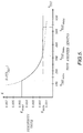
- K is a function of true air speed.
- V TAS is in knots. 57.3 approximates the arc tangent of the quotient.
- 101.27 converts V TAS from knots to Equation (3) produces a command that is equivalent in magnitude to the change in flight path angle necessary to achieve a target vertical air speed.
- K max which occurs at very low air speeds, prevents the displaying of excessively large TCAS RA pitch guidance symbols.
- K decreases linearly, until a given upper limit true air speed value is reached, above which a constant lower boundary of K (K min ) is maintained. This ensures that adequate displacement of the pitch axis leg 53 will occur even when true air speed is high. If this is not done at high true air speed, the sensitivity of the display may not be adequate in getting a pilot's attention to precisely fly in the commanded manner.
- ⁇ (ts/ts+ 1) is subtracted from the first part of the equation to account for the fact that changes in flight path angle lag changes in pitch attitude.
- the same term is used to "quicken" the inertial flight path angle included on some attitude displays.
- the term is subtracted so that the command appears to be fixed with respect to the horizon reference line 40 for as long as the pitch of the airplane is changed at a normal to moderate rate.
- the position of the pitch axis leg 53 is limited by the position of the Pitch Limit Indicator (PLI) symbol 41.
- PPI Pitch Limit Indicator
- the maximum TCAS RA pitch indication for both up and down advisories is limited to a fixed value of pitch scale degrees. This is done to prevent very large commands from causing the pitch axis leg to disappear off the edge of the electronic attitude display 21.
- FIGURE 6 illustrates a TCAS RA pitch guidance symbol 81 usable in connection with electronic attitude displays wherein the airplane symbol 83, the flight director symbol 85 and the Pitch Limit Indicator (PLI) symbol 87 are all in the form of inverted Vs (integrated cue format).
- PPI Pitch Limit Indicator
- the pitch axis leg 89 of the TCAS RA pitch guidance symbol 81 is also in the form of an inverted V.
- FIGURE 7 illustrates an electronic attitude display having a TCAS RA pitch guidance symbol 91 similar to the TCAS RA pitch guidance symbol 81 illustrated in FIGURE 6. Also like FIGURE 6, the airplane symbol 93, the flight director symbol 95 and the Pitch Limit Indicator (PLI) symbol 97 are in the form of inverted Vs. The primary difference between FIGURE 6 and FIGURE 7 is the addition of an inverted V 98 located at the end of the TCAS RA pitch guidance symbol 91 for corrective RAs only.
- PPI Pitch Limit Indicator
- the additional inverted V 98 is in a color (e.g., magenta or green) that is different from either the TCAS RA pitch guidance symbol 91 (e.g., red) and the Pitch Limit Indicator (PLI) symbol (e.g., yellow).
- the use of the additional inverted V directs a pilot's attention to a pitch angle that will eliminate a collision threat without using excessive pitch.
- the additional inverted V is only generated when a corrective resolution advisory, as opposed to a preventive resolution advisory, is being generated.
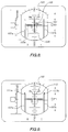
- FIGURE 8 illustrates a display wherein the airplane symbol 101, the Pitch Limit Indicator (PLI) symbol 103 and the flight director symbol 105 are the same as shown in FIGURES 1 and 2.
- the TCAS RA pitch axis guidance symbol illustrated in FIGURE 8 is formed by a pair of wide vertically oriented bars 107a and 107b.
- the vertically oriented bars 107a and 107b lie at the outer ends of the right and left wings 109a and 109b of the airplane symbol 101.
- the height of the bars is, of course, controlled by the magnitude of the RA CMD data signal.
- FIGURE 9 illustrates a display identical to that shown in FIGURE 8 with the addition of narrow, short vertical legs 111a and 111b located atop the wider vertical legs 107a and 107b. Also, centrally located between the short vertical legs 111a and 111b, along the pitch axis scale, is a U-shaped symbol 113. The horizontal leg of the U-shaped symbol 113 is in line with the tops of legs 107a and 107b and the tops of the vertical legs of the U-shaped symbol 113 are in line with the tops of the narrow, short legs 111a and 111b.
- the narrow, short legs 111a and 111b and the U-shaped symbol 113 are, like the extra inverted V 98 in the display illustrated in FIGURE 7, designed to direct a pilot's attention to the pitch angles need to avoid a collision threat.
- the color (e.g., green) of the narrow, short vertical legs 111a and 111b and the U-shaped symbol 113 is different from the color (e.g., red) of legs 107a and 107b (e.g., red) and the color (e.g., yellow) of the Pitch Limit Indicator (PLI) symbol 103.
- the short narrow legs can exist whenever a resolution advisory symbol is present, preferably they only exist when the resolution advisory is corrective.
- FIGURE 10 illustrates a display generally similar to the display illustrated in FIGURES 1 and 2 except that the TCAS RA pitch guidance symbol 121 (for corrective RAs) does not include a pitch axis leg. Rather, located atop each of the inclined legs 123a and 123b of the TCAS RA pitch guidance symbol 121 is a block-like symbol 125a and 125b.
- the color (e.g., green) of the block-like symbols is different from the color (e.g., red) of the inclined legs 123a and 123b and the color (e.g., yellow) of the Pitch Limit Indicator (PLI) symbol 127.
- PPI Pitch Limit Indicator
- the difference in shape and color directs a pilot's eyes toward the pitch angle required to avoid a collision threat.
- the block-like symbols 125a and 125b can exist whenever a resolution advisory is present, preferably they are not present when the resolution advisory is preventive.
- FIGURES 1, 2 and 6-10 have all illustrated up Resolution Advisory situations, i.e., situations where the pilot is advised to climb (corrective advisory) or where the pilot is advised that a threat will be avoided if the airplane does not descend (preventive advisory).
- FIGURE 11 illustrates the opposite, i.e., a down Resolution Advisory. That is, FIGURE 11 illustrates a display that shows the converse of the display illustrated in FIGURES 1 and 2. More specifically, as described above, the TCAS RA pitch guidance symbol 51 illustrated in FIGURES 1 and 2 outlines an area that is to be avoided, i.e., the symbol tells the pilot to pitch the airplane up such that the airplane symbol stays outside of the area enclosed by the TCAS RA pitch guidance symbol 51.
- FIGURE 11 also illustrates a TCAS RA pitch guidance symbol 131 formed by a pitch axis leg 133 and a pair of diverging legs 135a and 135b.
- the portion of the pitch axis lying outside of the outlined area is safe, i.e., it is a region wherein the threat of a collision is avoided.
- the outlined area lies above, rather than below, the airplane symbol 137.
- the pilot is advised that a threat will be avoided if the airplane does not climb.
- the pilot is also advised that the airplane can descend.
- the invention provides an airplane pitch guidance control law and display symbol for a Traffic alert and Collision Avoidance System (TCAS).
- TCAS II computer evaluates a traffic threat and determines a vertical speed command for an up or down advisory.
- the TCAS II vertical speed command is modified by a pitch attitude guidance control law to create a signal suitable for controlling the distance between the reference point of an airplane symbol and a limit, which may be in the form of a horizontal bar or other horizontal symbol.
- the pitch attitude guidance control law determines the difference between the vertical air speed of the aircraft and the TCAS commanded vertical air speed and multiplies this difference by a sensitivity value and a value that approximates the arc tangent of the quotient. From the resultant value is subtracted a factor that accounts for the fact that changes in flight path angle lag changes in pitch attitude.
Landscapes
- Engineering & Computer Science (AREA)
- Physics & Mathematics (AREA)
- Aviation & Aerospace Engineering (AREA)
- General Physics & Mathematics (AREA)
- Radar, Positioning & Navigation (AREA)
- Remote Sensing (AREA)
- Automation & Control Theory (AREA)
- Electromagnetism (AREA)
- Computer Networks & Wireless Communication (AREA)
- Traffic Control Systems (AREA)
- Navigation (AREA)
Applications Claiming Priority (2)
| Application Number | Priority Date | Filing Date | Title |
|---|---|---|---|
| US07/803,032 US5248968A (en) | 1991-12-06 | 1991-12-06 | Tcas ii pitch guidance control law and display symbol |
| US803032 | 1997-02-19 |
Publications (3)
| Publication Number | Publication Date |
|---|---|
| EP0545473A2 true EP0545473A2 (fr) | 1993-06-09 |
| EP0545473A3 EP0545473A3 (en) | 1995-03-22 |
| EP0545473B1 EP0545473B1 (fr) | 1998-01-21 |
Family
ID=25185387
Family Applications (1)
| Application Number | Title | Priority Date | Filing Date |
|---|---|---|---|
| EP92203644A Expired - Lifetime EP0545473B1 (fr) | 1991-12-06 | 1992-11-25 | Loi de contrÔle de guidage de tanguage pour TCAS II et symbole d'affichage |
Country Status (3)
| Country | Link |
|---|---|
| US (1) | US5248968A (fr) |
| EP (1) | EP0545473B1 (fr) |
| DE (1) | DE69224167T2 (fr) |
Cited By (10)
| Publication number | Priority date | Publication date | Assignee | Title |
|---|---|---|---|---|
| FR2725803A1 (fr) * | 1994-10-18 | 1996-04-19 | Sextant Avionique | Dispositif optoelectronique d'assistance au pilotage d'un aeronef |
| EP0730212A3 (fr) * | 1995-03-02 | 1997-04-23 | Sextant Avionique | Dispositif de contrÔle d'un système d'aéronef en pilotage manuel utilisant notamment un collimateur tête haute |
| WO2003066433A1 (fr) * | 2002-02-06 | 2003-08-14 | Honeywell International, Inc. | Appareil pour guidage d'un avion en detresse |
| FR2876483A1 (fr) * | 2004-10-08 | 2006-04-14 | Airbus France Sas | Procede et systeme d'evitement pour un aeronef |
| EP2073186A3 (fr) * | 2007-12-17 | 2009-08-26 | The Boeing Company | Procédé et système pour afficher une référence de guidage pour la sensibilisation à la situation de trafic |
| FR2936343A1 (fr) * | 2008-09-23 | 2010-03-26 | Airbus France | Procede et dispositif pour limiter le nombre des alertes emises par un systeme anticollision monte a bord d'un avion |
| FR2956512A1 (fr) * | 2010-02-16 | 2011-08-19 | Airbus Operations Sas | Procede et dispositif de protection automatique d'un aeronef contre un taux de descente excessif. |
| CN102867435A (zh) * | 2011-06-27 | 2013-01-09 | 通用电气公司 | 在飞行显示器上在视觉上指示来自空中防撞系统的报告的方法 |
| EP2738099A1 (fr) * | 2012-11-30 | 2014-06-04 | Airbus | Aide au pilotage d'un aéronef en situation de décrochage |
| US11096950B2 (en) | 2006-11-01 | 2021-08-24 | Barbara Brooke Jennings | Compounds, methods, and treatments for abnormal signaling pathways for prenatal and postnatal development |
Families Citing this family (39)
| Publication number | Priority date | Publication date | Assignee | Title |
|---|---|---|---|---|
| US5382954A (en) * | 1993-05-27 | 1995-01-17 | Honeywell Inc. | Resolution advisory display instrument for TCAS guidance |
| US5983161A (en) | 1993-08-11 | 1999-11-09 | Lemelson; Jerome H. | GPS vehicle collision avoidance warning and control system and method |
| EP0704677B1 (fr) * | 1994-10-02 | 1998-04-15 | Fokker Technology B.V. | Dispositif d'affichage de contrÔle de guidage pour TCAS III |
| FR2733061B1 (fr) * | 1995-04-13 | 1997-05-23 | Sextant Avionique | Dispositif optoelectronique d'aide au pilotage d'un aeronef par mauvaise visibilite |
| US5797562A (en) * | 1995-07-26 | 1998-08-25 | Honeywell, Inc. | Aircraft display combining error tape and reference bugs |
| US5566074A (en) * | 1995-08-07 | 1996-10-15 | The Mitre Corporation | Horizontal miss distance filter system for suppressing false resolution alerts |
| US6028536A (en) * | 1995-11-16 | 2000-02-22 | Northrop Grumman Corporation | Integrated flight control indicator |
| US5912627A (en) * | 1997-10-17 | 1999-06-15 | Alexander; William J. | Device and method for indicating if an airplane is operating within operating limits |
| US6118385A (en) * | 1998-09-09 | 2000-09-12 | Honeywell Inc. | Methods and apparatus for an improved control parameter value indicator |
| US6177888B1 (en) | 1999-09-08 | 2001-01-23 | The Boeing Company | Wake turbulence warning and caution system and method |
| US6512975B2 (en) | 2000-04-07 | 2003-01-28 | Honeywell International Inc. | Traffic information service (TIS) uplink own aircraft heading correction |
| US6686851B1 (en) * | 2000-08-25 | 2004-02-03 | Rockwell Collins | Altitude tape and integral vertical speed indicator |
| US6907324B2 (en) * | 2000-10-11 | 2005-06-14 | Honeywell International Inc. | Instrument reference flight display system for horizon representation of direction to next waypoint |
| DE10102938B4 (de) * | 2001-01-23 | 2007-10-11 | Eurocopter Deutschland Gmbh | Nicklage-Symbolik |
| CA2453031A1 (fr) | 2001-07-06 | 2003-01-16 | Goodrich Avionics Systems, Inc. | Systeme et procede pour la vision de synthese d'un systeme de visualisation du sol |
| FR2831871B1 (fr) * | 2001-11-08 | 2004-08-13 | Airbus France | Procede et dispositif d'aide au pilotage d'un aeronef |
| US6789016B2 (en) * | 2002-06-12 | 2004-09-07 | Bae Systems Information And Electronic Systems Integration Inc. | Integrated airborne transponder and collision avoidance system |
| US7205907B2 (en) * | 2003-09-15 | 2007-04-17 | Universal Avionics Systems Corporation | Non linear tape display |
| US7046170B2 (en) * | 2003-09-15 | 2006-05-16 | Universal Avionics Systems Corporation | ANP/RNP display |
| US7095338B2 (en) * | 2003-10-07 | 2006-08-22 | Ted Naimer | TCAS VSI display |
| US7412308B2 (en) * | 2003-10-07 | 2008-08-12 | Universal Avionics Systems Corp. | Dynamic VSI display |
| US7724178B2 (en) * | 2004-12-17 | 2010-05-25 | Honeywell International Inc. | Traffic alert collision avoidance system (TCAS) devices and methods |
| US20080004756A1 (en) * | 2006-06-02 | 2008-01-03 | Innovative Solutions & Support, Inc. | Method and apparatus for display of current aircraft position and operating parameters on a graphically-imaged chart |
| FR2921181B1 (fr) * | 2007-09-14 | 2010-06-11 | Thales Sa | Procede de presentation d'informations d'anti-collision dans un viseur tete haute pour aeronef |
| US9091545B2 (en) * | 2007-11-27 | 2015-07-28 | Florida Institute For Human And Machine Cognition, Inc. | Motion-resolving hover display |
| US8188889B2 (en) * | 2007-12-14 | 2012-05-29 | The Boeing Company | Method and system for display of traffic information in the flight deck |
| CN103914888B (zh) * | 2014-03-31 | 2016-05-11 | 四川九洲空管科技有限责任公司 | 一种机载防撞系统数据记录分析方法 |
| US9969503B2 (en) * | 2016-07-21 | 2018-05-15 | Rockwell Collins, Inc. | Head-up display (HUD) stall recovery symbology |
| US10460613B2 (en) * | 2017-09-26 | 2019-10-29 | Honeywell International Inc. | Method and system for displaying an alignment symbol for indicating deviations between ownship runway course heading and tracking |
| US20190283862A1 (en) * | 2018-03-16 | 2019-09-19 | Honeywell International Inc. | Flight control system |
| US11164471B1 (en) | 2019-10-04 | 2021-11-02 | The Boeing Company | System for previewing vertical speed guidance following an air traffic conflict alert |
| CN114333429B (zh) * | 2021-12-21 | 2022-12-09 | 中国电子科技集团公司第五十四研究所 | 一种面向多无人机目标覆盖任务的规则提取方法 |
| USD1122957S1 (en) * | 2024-12-09 | 2026-04-21 | Jeppesen Foreflight, Inc. | Display screen or portion thereof with animated graphical user interface |
| USD1122956S1 (en) * | 2024-12-09 | 2026-04-21 | Jeppesen Foreflight, Inc. | Display screen or portion thereof with animated graphical user interface |
| USD1122955S1 (en) * | 2024-12-09 | 2026-04-21 | Jeppesen Foreflight, Inc. | Display screen or portion thereof with animated graphical user interface |
| USD1121651S1 (en) * | 2024-12-09 | 2026-04-07 | Jeppesen Foreflight, Inc. | Display screen or portion thereof with animated graphical user interface |
| USD1121652S1 (en) * | 2024-12-09 | 2026-04-07 | Jeppesen Foreflight, Inc. | Display screen or portion thereof with animated graphical user interface |
| USD1122274S1 (en) * | 2024-12-09 | 2026-04-14 | Jeppesen Foreflight, Inc. | Display screen or portion thereof with graphical user interface |
| USD1121653S1 (en) * | 2024-12-09 | 2026-04-07 | Jeppesen Foreflight, Inc. | Display screen or portion thereof with animated graphical user interface |
Family Cites Families (17)
| Publication number | Priority date | Publication date | Assignee | Title |
|---|---|---|---|---|
| US3521227A (en) * | 1966-10-10 | 1970-07-21 | Kaiser Aerospace & Electronics | Display system for providing integrated display of aircraft information |
| US4060805A (en) * | 1976-06-28 | 1977-11-29 | The Bendix Corporation | Integrated terminal area surveillance system |
| FR2487505A1 (fr) * | 1980-07-23 | 1982-01-29 | Dassault Avions | Dispositif d'assistance au pilotage d'un vehicule aerien |
| US4454496A (en) * | 1980-10-30 | 1984-06-12 | Mcdonald Douglas Corporation | Conformal head-up display |
| US4563742A (en) * | 1983-09-26 | 1986-01-07 | Rockwell International Corporation | Combined motion cueing attitude indicator |
| US4782450A (en) * | 1985-08-27 | 1988-11-01 | Bennett Flax | Method and apparatus for passive airborne collision avoidance and navigation |
| US4910513A (en) * | 1985-11-20 | 1990-03-20 | The Boeing Company | Apparatus and methods for generating a stall warning margin on an aircraft attitude indicator display |
| US4710774A (en) * | 1986-02-18 | 1987-12-01 | Gunny Edmond R | Aircraft collision avoidance system |
| US4870425A (en) * | 1986-02-18 | 1989-09-26 | Gunny Edmond R | Communications system |
| US4910526A (en) * | 1987-05-18 | 1990-03-20 | Avion Systems, Inc. | Airborne surveillance method and system |
| US4794354A (en) * | 1987-09-25 | 1988-12-27 | Honeywell Incorporated | Apparatus and method for modifying microwave |
| US4914733A (en) * | 1987-10-30 | 1990-04-03 | Allied-Signal, Inc. | Traffic advisory-instantaneous vertical speed display |
| US4855748A (en) * | 1988-03-18 | 1989-08-08 | Allied-Signal Inc. | TCAS bearing estimation receiver using a 4 element antenna |
| US4899157A (en) * | 1989-04-03 | 1990-02-06 | Allied-Signal Inc. | Leading edge detector/reply quantizer |
| US4945550A (en) * | 1989-04-07 | 1990-07-31 | Allied-Signal Inc. | ATCRBS/SIF/TCAS reply decoder |
| CA2018006A1 (fr) * | 1989-06-30 | 1990-12-31 | William R. Hancock | Affichage routier avec perspective |
| US5185606A (en) * | 1990-05-08 | 1993-02-09 | Fokker Aircraft B.V. | Primary flight display presenting resolution advisory information provided by a traffic alert and collision avoidance system |
-
1991
- 1991-12-06 US US07/803,032 patent/US5248968A/en not_active Expired - Lifetime
-
1992
- 1992-11-25 EP EP92203644A patent/EP0545473B1/fr not_active Expired - Lifetime
- 1992-11-25 DE DE69224167T patent/DE69224167T2/de not_active Expired - Fee Related
Cited By (23)
| Publication number | Priority date | Publication date | Assignee | Title |
|---|---|---|---|---|
| FR2725803A1 (fr) * | 1994-10-18 | 1996-04-19 | Sextant Avionique | Dispositif optoelectronique d'assistance au pilotage d'un aeronef |
| EP0708394A1 (fr) * | 1994-10-18 | 1996-04-24 | Sextant Avionique | Dispositif optoélectronique d'assistance au pilotage d'un aéronef |
| US5675327A (en) * | 1994-10-18 | 1997-10-07 | Sextant Avionique | Optoelectronic device for assistance in the piloting of an aircraft |
| EP0730212A3 (fr) * | 1995-03-02 | 1997-04-23 | Sextant Avionique | Dispositif de contrÔle d'un système d'aéronef en pilotage manuel utilisant notamment un collimateur tête haute |
| WO2003066433A1 (fr) * | 2002-02-06 | 2003-08-14 | Honeywell International, Inc. | Appareil pour guidage d'un avion en detresse |
| FR2876483A1 (fr) * | 2004-10-08 | 2006-04-14 | Airbus France Sas | Procede et systeme d'evitement pour un aeronef |
| WO2006040441A1 (fr) * | 2004-10-08 | 2006-04-20 | Airbus France | Procede et systeme d'evitement pour un aeronef |
| US8725401B2 (en) | 2004-10-08 | 2014-05-13 | Airbus Operations Sas | Avoidance method and system for an aircraft |
| US11096950B2 (en) | 2006-11-01 | 2021-08-24 | Barbara Brooke Jennings | Compounds, methods, and treatments for abnormal signaling pathways for prenatal and postnatal development |
| US8041504B2 (en) | 2007-12-17 | 2011-10-18 | The Boeing Company | Method and system for display of guidance reference for traffic situational awareness |
| US8315787B2 (en) | 2007-12-17 | 2012-11-20 | The Boeing Company | Method and system for display of guidance reference for traffic situational awareness |
| EP2073186A3 (fr) * | 2007-12-17 | 2009-08-26 | The Boeing Company | Procédé et système pour afficher une référence de guidage pour la sensibilisation à la situation de trafic |
| FR2936343A1 (fr) * | 2008-09-23 | 2010-03-26 | Airbus France | Procede et dispositif pour limiter le nombre des alertes emises par un systeme anticollision monte a bord d'un avion |
| US8296054B2 (en) | 2008-09-23 | 2012-10-23 | Airbus Operations Sas | Method and device for limiting the number of alarms generated by an anti-collision system on board an airplane |
| US8818577B2 (en) | 2010-02-16 | 2014-08-26 | Airbus Operations (Sas) | Method and device for automatically protecting an aircraft against an excessive descent rate |
| FR2956512A1 (fr) * | 2010-02-16 | 2011-08-19 | Airbus Operations Sas | Procede et dispositif de protection automatique d'un aeronef contre un taux de descente excessif. |
| US8624757B2 (en) | 2011-06-27 | 2014-01-07 | General Electric Company | Method for visually indicating an advisory from the traffic collision avoidance system on a flight display |
| EP2541527A3 (fr) * | 2011-06-27 | 2013-07-03 | General Electric Company | Procédé pour indiquer visuellement un avis de sécurité à partir du système d'évitement de collision de trafic sur un écran de vol |
| CN102867435A (zh) * | 2011-06-27 | 2013-01-09 | 通用电气公司 | 在飞行显示器上在视觉上指示来自空中防撞系统的报告的方法 |
| EP2738099A1 (fr) * | 2012-11-30 | 2014-06-04 | Airbus | Aide au pilotage d'un aéronef en situation de décrochage |
| FR2998873A1 (fr) * | 2012-11-30 | 2014-06-06 | Airbus | Aide au pilotage d'un aeronef en situation de decrochage |
| US9174742B2 (en) | 2012-11-30 | 2015-11-03 | Airbus (Sas) | Assistance with piloting of an aircraft in a stall |
| CN103847971B (zh) * | 2012-11-30 | 2018-01-02 | 空中客车股份有限公司 | 失速状态的飞行器的辅助驾驶 |
Also Published As
| Publication number | Publication date |
|---|---|
| EP0545473B1 (fr) | 1998-01-21 |
| DE69224167T2 (de) | 1998-05-07 |
| US5248968A (en) | 1993-09-28 |
| EP0545473A3 (en) | 1995-03-22 |
| DE69224167D1 (de) | 1998-02-26 |
Similar Documents
| Publication | Publication Date | Title |
|---|---|---|
| US5248968A (en) | Tcas ii pitch guidance control law and display symbol | |
| US4368517A (en) | Aircraft landing display system | |
| US6021374A (en) | Stand alone terrain conflict detector and operating methods therefor | |
| US7962254B2 (en) | Method and system for assisting flight control of a low-flying aircraft | |
| US6720891B2 (en) | Vertical situation display terrain/waypoint swath, range to target speed, and blended airplane reference | |
| EP3961603B1 (fr) | Procédés et systèmes d'affichage de guidage d'évasion horizontale | |
| EP0938645B1 (fr) | Procede d'alignement conforme avec la piste sur un collimateur de pilotage tete haute et dispositif correspondant | |
| CA1238398A (fr) | Systeme-temoin d'accidents du terrain | |
| US9499279B2 (en) | System and method for displaying runway approach information | |
| EP3012590B1 (fr) | Système et procédé pour afficher des informations d'atterrissage sur piste | |
| US6995690B1 (en) | Vertical situation display terrain/waypoint swath, range to target speed, and blended airplane reference | |
| EP1896797B1 (fr) | Affichage de vol primaire a vue en perspective avec lignes de traçage de terrain | |
| US3784969A (en) | Aircraft landing display apparatus | |
| US8629787B1 (en) | System, module, and method for presenting clearance-dependent advisory information in an aircraft | |
| US6255965B1 (en) | Device for aiding the piloting of an aircraft, especially a rotary-wing aircraft and in particular a helicopter | |
| JPH0543966B2 (fr) | ||
| WO2018020303A1 (fr) | Système et procédé d'affichage de trajectoire de vol en 3d | |
| EP3048423B1 (fr) | Appareil et procédé pour afficher une direction de visualisation du système de vision synthétique | |
| EP1775553B1 (fr) | Viseur d'attitude d'aéronef tête basse centré hybride et procédé de calcul de la limite d'angle de dérive affichée | |
| EP1764759A1 (fr) | Système et procédé d'affichage des espaces aérien protégé ou interdit dans un avion | |
| US11450219B2 (en) | Aircraft system and method for assisting a pilot during flight | |
| US6480763B1 (en) | Method and system for providing an aircraft drift advisory | |
| EP2801964A1 (fr) | Système et procédé d'affichage de vitesse ascensionnelle sur un indicateur de vitesse verticale avionique | |
| EP1200949B1 (fr) | Balayage de terrain/point de cheminement afficheur de position verticale, distance par rapport a la vitesse preaffichee et reference ponderee de l'avion | |
| EP0704677A1 (fr) | Dispositif d'affichage de contrÔle de guidage pour TCAS III |
Legal Events
| Date | Code | Title | Description |
|---|---|---|---|
| PUAI | Public reference made under article 153(3) epc to a published international application that has entered the european phase |
Free format text: ORIGINAL CODE: 0009012 |
|
| AK | Designated contracting states |
Kind code of ref document: A2 Designated state(s): DE FR GB NL |
|
| PUAL | Search report despatched |
Free format text: ORIGINAL CODE: 0009013 |
|
| AK | Designated contracting states |
Kind code of ref document: A3 Designated state(s): DE FR GB NL |
|
| 17P | Request for examination filed |
Effective date: 19950705 |
|
| 17Q | First examination report despatched |
Effective date: 19961212 |
|
| GRAG | Despatch of communication of intention to grant |
Free format text: ORIGINAL CODE: EPIDOS AGRA |
|
| GRAH | Despatch of communication of intention to grant a patent |
Free format text: ORIGINAL CODE: EPIDOS IGRA |
|
| GRAH | Despatch of communication of intention to grant a patent |
Free format text: ORIGINAL CODE: EPIDOS IGRA |
|
| GRAA | (expected) grant |
Free format text: ORIGINAL CODE: 0009210 |
|
| AK | Designated contracting states |
Kind code of ref document: B1 Designated state(s): DE FR GB NL |
|
| REF | Corresponds to: |
Ref document number: 69224167 Country of ref document: DE Date of ref document: 19980226 |
|
| ET | Fr: translation filed | ||
| PLBE | No opposition filed within time limit |
Free format text: ORIGINAL CODE: 0009261 |
|
| 26N | No opposition filed | ||
| REG | Reference to a national code |
Ref country code: GB Ref legal event code: IF02 |
|
| PGFP | Annual fee paid to national office [announced via postgrant information from national office to epo] |
Ref country code: NL Payment date: 20051029 Year of fee payment: 14 |
|
| PG25 | Lapsed in a contracting state [announced via postgrant information from national office to epo] |
Ref country code: NL Free format text: LAPSE BECAUSE OF NON-PAYMENT OF DUE FEES Effective date: 20070601 |
|
| NLV4 | Nl: lapsed or anulled due to non-payment of the annual fee |
Effective date: 20070601 |
|
| PGFP | Annual fee paid to national office [announced via postgrant information from national office to epo] |
Ref country code: FR Payment date: 20081117 Year of fee payment: 17 |
|
| PGFP | Annual fee paid to national office [announced via postgrant information from national office to epo] |
Ref country code: DE Payment date: 20081223 Year of fee payment: 17 |
|
| PGFP | Annual fee paid to national office [announced via postgrant information from national office to epo] |
Ref country code: GB Payment date: 20081229 Year of fee payment: 17 |
|
| GBPC | Gb: european patent ceased through non-payment of renewal fee |
Effective date: 20091125 |
|
| REG | Reference to a national code |
Ref country code: FR Ref legal event code: ST Effective date: 20100730 |
|
| PG25 | Lapsed in a contracting state [announced via postgrant information from national office to epo] |
Ref country code: FR Free format text: LAPSE BECAUSE OF NON-PAYMENT OF DUE FEES Effective date: 20091130 |
|
| PG25 | Lapsed in a contracting state [announced via postgrant information from national office to epo] |
Ref country code: DE Free format text: LAPSE BECAUSE OF NON-PAYMENT OF DUE FEES Effective date: 20100601 |
|
| PG25 | Lapsed in a contracting state [announced via postgrant information from national office to epo] |
Ref country code: GB Free format text: LAPSE BECAUSE OF NON-PAYMENT OF DUE FEES Effective date: 20091125 |