EP0545535A1 - System zur Steuerung des Antriebsradschlupfes eines Motor-Fahrzeugs - Google Patents
System zur Steuerung des Antriebsradschlupfes eines Motor-Fahrzeugs Download PDFInfo
- Publication number
- EP0545535A1 EP0545535A1 EP92309664A EP92309664A EP0545535A1 EP 0545535 A1 EP0545535 A1 EP 0545535A1 EP 92309664 A EP92309664 A EP 92309664A EP 92309664 A EP92309664 A EP 92309664A EP 0545535 A1 EP0545535 A1 EP 0545535A1
- Authority
- EP
- European Patent Office
- Prior art keywords
- engine
- drivewheel
- torque
- wheel slip
- slip signal
- Prior art date
- Legal status (The legal status is an assumption and is not a legal conclusion. Google has not performed a legal analysis and makes no representation as to the accuracy of the status listed.)
- Withdrawn
Links
Images

Classifications
-
- B—PERFORMING OPERATIONS; TRANSPORTING
- B60—VEHICLES IN GENERAL
- B60K—ARRANGEMENT OR MOUNTING OF PROPULSION UNITS OR OF TRANSMISSIONS IN VEHICLES; ARRANGEMENT OR MOUNTING OF PLURAL DIVERSE PRIME-MOVERS IN VEHICLES; AUXILIARY DRIVES FOR VEHICLES; INSTRUMENTATION OR DASHBOARDS FOR VEHICLES; ARRANGEMENTS IN CONNECTION WITH COOLING, AIR INTAKE, GAS EXHAUST OR FUEL SUPPLY OF PROPULSION UNITS IN VEHICLES
- B60K28/00—Safety devices for propulsion-unit control, specially adapted for, or arranged in, vehicles, e.g. preventing fuel supply or ignition in the event of potentially dangerous conditions
- B60K28/10—Safety devices for propulsion-unit control, specially adapted for, or arranged in, vehicles, e.g. preventing fuel supply or ignition in the event of potentially dangerous conditions responsive to conditions relating to the vehicle
- B60K28/16—Safety devices for propulsion-unit control, specially adapted for, or arranged in, vehicles, e.g. preventing fuel supply or ignition in the event of potentially dangerous conditions responsive to conditions relating to the vehicle responsive to, or preventing, spinning or skidding of wheels
Definitions
- the present invention relates to a system for controlling unwanted drivewheel slip of vehicles equipped with internal combustion engines.
- Automotive designers have utilized electronic engine controls for the purpose of providing increased traction by reducing engine torque in response to the spinning of driven road wheels.
- U.S. 4,856,610 to Leiber et al. discloses a system for operating an air throttle, engine fuel supply and engine spark advance in response to unwanted wheel spin.
- U.S. 4,513,721 to Ina et al. and U.S. 4,860,849 to Andersson et al. disclose additional systems for controlling the engine's air/fuel ratio in response to the need to control engine torque, as is the case when one or more drivewheels is slipping.
- Known anti-wheel spin systems suffer from the following disadvantages.
- systems which utilize spark timing changes or air/fuel ratio modulation have a limited range of authority and have the capability of reducing torque by only about 30-50% before the engine is operated under misfire conditions, which are detrimental in terms of increased engine emissions.
- exhaust aftertreatment catalyst durability may be adversely affected by excessive operation of the engine in a misfire condition.
- Wheelspin limiting systems which rely on series throttles or control of the pressure in the intake manifold have inadequate time response characteristics because typical intake manifolds have a volume which is large in comparison with engine displacement -- typically, 0.5 to 3.0 times displacement. Because engine torque output cannot be changed faster than the time constant of the manifold pressure change with such systems, the response time of the engine's torque output is compromised.
- a system using intake valve throttling in the form of intake valve timing or lift control, or both, according to the present invention will allow airflow to be changed for each intake event, and this system will therefore permit rapid response to wheelspin.
- intake manifold pressure may be controlled so as to be close to atmospheric pressure, so as to minimize engine pumping work losses.
- a system embodying the present invention offers an advantage insofar as it will use less fuel during transient load control modes.
- a system embodying the present invention is advantageous because exhaust emissions during torque control will be reduced.
- a further advantage of the system embodying the present invention is the elimination of the need to use brake controls, which are employed in some traction enhancement or wheelspin prevention systems.
- a system for controlling unwanted drivewheel spin in an automotive vehicle powered by an internal combustion engine, having a plurality of intake and exhaust valves includes sensor means for measuring the relative velocity of at least one drivewheel with respect to the ground speed of the vehicle, comparator means for comparing the measured relative velocity of the drivewheel to a threshold value and for generating a wheelslip signal in the event that the threshold is exceeded, and torque modulation means, responsive to said wheelslip signal, for modulating the output torque of the engine with the torque modulation means comprising actuator means for operating the engine valves.
- the means for operating valves of the engine preferably comprises a plurality of hydraulically powered actuators, with at least one such actuator operatively associated with each engine valve, with the actuator means further comprising a source of hydraulic power coupled to a hydraulic circuit operated by the torque modulation means for supplying pressurized hydraulic fluid to the hydraulic actuators.
- the torque modulation means may additionally be responsive to the speed of the engine and to the position of a throttle associated with the engine. Further, the torque modulation means may be responsive to the charge air pressure within an intake manifold associated with the engine.
- the actuator means for operating the valves of the engine may utilize a source of hydraulic power comprising an engine driven pump coupled to a hydraulic actuator by means of a hydraulic circuit, including a solenoid valve mechanism, which is operated by the torque modulation means.
- the actuator means may comprise an electromechanical device of the type disclosed in U.S. 4,515,343 to Pischinger, et al., which is hereby incorporated by reference into this specification.
- the actuator means may be operatively associated with either the intake valves, or the exhaust valves, or both sets of valves.
- a system according to the present invention senses that the relative rotational velocity of a drivewheel exceeds a predetermined threshold value, the torque output of the engine will be reduced until the relative rotational velocity no longer exceeds the threshold value.
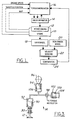
- an engine, 10, having at least one drivewheel, 18, driven thereby, is incorporated in a system for controlling unwanted slip of the drivewheel.
- a system according to the present invention may be used with vehicles having multiple powered wheels and having multicylinder engines with a plurality of intake and exhaust valves.
- Other elements of the present system include a torque modulator, 16, which may receive inputs from the engine in terms of engine speed, throttle position, and charge air pressure or mass airflow (labeled collectively as "MAP" in Figure 1) within the engine's intake manifold.
- MAP charge air pressure or mass airflow
- Torque modulator 16 also receives input from a comparator, 24. Torque modulator 16 serves as the system controller.
- Comparator 24 compares the sensed velocity of drivewheel 18 with the sensed velocity of non-driven wheel 20, as determined by sensors 22, and in the event that the a threshold value is exceeded, comparator 24 generates a wheel slip signal and sends that signal to torque modulator 16.
- torque modulator 16 and comparator 24, as well as other electronic components of the present system may be combined in a single microprocessor computer in the manner of current engine controls and anti-lock braking controls.
- torque modulator 16 Upon receipt of the wheel slip signal, torque modulator 16 will command valve operator 14 to reduce the torque output of engine 10. Valve operator 14 may accomplish this by operating the intake valves in a manner so as to induct less intake charge into engine 10. This will have the direct result of reducing the torque output of the engine. Although control of the intake valves is preferred, the valve operator may be applied to only the exhaust valves of the engine, so as to limit the torque output of engine 10 by opening the exhaust valves earlier or later than would otherwise be the case. Torque modulator 16 may use a proportional control algorithm, or a proportional-integral-derivative algorithm, or yet other types of algorithms known to those skilled in the art and suggested by this disclosure.
- FIG. 2 illustrates a first embodiment of valve operator 14.
- an engine valve, 12, which is an intake valve in this case is biased into the closed position by means of a valve spring, 30.
- the valve is opened by means of a hydraulically powered linear actuator, 34.
- Hydraulic actuator 34 includes a piston, 56, mounted for reciprocation within a cylinder, 58. Hydraulic fluid is provided to cylinder 58 by means of a supply valve, 32, and a drain valve, 36.
- valve 12 will lift off its seat only when valve 36 is closed and valve 32 has been opened sufficiently to permit hydraulic pressure to build within cylinder 58, so as to act upon piston 56. Because inertia will cause valve 12 to continue moving even after pressure from valve 32 has been cut off, check valve 82 is provided to allow hydraulic fluid to enter cylinder 58 from hydraulic return line 68.
- Valve 12 is closed by returning drain valve 36 to its normally open position, thereby allowing the pressure acting on piston 56 to decay as hydraulic fluid leaves cylinder 58 via drain outlet 60 and restricted drain outlet 62.
- drain valve 36 has a construction which mimics that of supply valve 32, except that valve 36 is of the normally open variety.
- Valve 36 has a spool, 74, housed within a casing, 78.
- spool 74 is responsive to signals from torque modulator 16, which act on armature 72 via coil 70. Fluid passing through valve 36 is introduced into casing 78 by inlet port 64, and leaves the casing by outlet port 66.
- spool 74 is urged into its no-signal position (i.e., the open position), by means of a spring, 76.
- U.S. 5,056,378 to Aimone et al. which is assigned to the assignee of the present invention, contains a description of a similar hydraulic valve actuation system for use with torque modulation means of a vehicle transmission.
- the '378 patent is hereby incorporated by reference in this specification, as is U.S. 4,957,074 to Weissler, II et al., which discloses yet another electronic valve control device and system for an internal combustion engine, which system is suitable for practicing the valve actuation feature according to the present invention.
- FIG. 3 is a schematic representation of a lost motion type of valve operator suitable for practicing the present invention.
- valve 12 which is biased as before into a closed position by spring 30, is operated by piston 90, which is reciprocably housed within cylinder 92.
- Hydraulic fluid is pumped by means of a piston pump, including a piston, 94, which is reciprocably housed within a cylinder, 106, with the piston being driven by means of an engine driven cam, 96.
- the amount of hydraulic oil pumped by piston 94 which ultimately reaches cylinder 92, is determined by the action of solenoid valve, 98, which is controlled by torque modulator 16.
- valve 98 When solenoid valve 98 is closed, all of the oil pumped by piston 94, less any oil leaking past pistons 90 and 94, will be transmitted to cylinder 92 and valve 12 will be opened by an amount related to the relative swept volumes of the cylinders and the displacement provided by cam 96. If, on the other hand, valve 98 is in the open position, some of the hydraulic fluid will be allowed to pass into an accumulator comprising a piston, 100, which is loaded by a spring, 104, and which is mounted reciprocably within cylinder 102.
- a system according to the present invention will control unwanted drivewheel spin of an automotive vehicle by reducing engine output torque once excessive drivewheel spin has been detected; thereafter, output torque will be maintained by torque modulator 16 in a reduced state until the undesired wheelspin is brought under control.
- the controlled state may be defined as a range for the relative rotational velocity of the drivewheel, such that torque modulator will maintain such velocity within a predetermined range.
- the controlled state may be defined as a threshold value for the relative rotational velocity of the drivewheel, such that torque modulator will maintain such velocity below the threshold value.
Landscapes
- Engineering & Computer Science (AREA)
- Chemical & Material Sciences (AREA)
- Combustion & Propulsion (AREA)
- Transportation (AREA)
- Mechanical Engineering (AREA)
- Control Of Vehicle Engines Or Engines For Specific Uses (AREA)
- Electrical Control Of Air Or Fuel Supplied To Internal-Combustion Engine (AREA)
Applications Claiming Priority (2)
| Application Number | Priority Date | Filing Date | Title |
|---|---|---|---|
| US80259891A | 1991-12-05 | 1991-12-05 | |
| US802598 | 1997-02-19 |
Publications (1)
| Publication Number | Publication Date |
|---|---|
| EP0545535A1 true EP0545535A1 (de) | 1993-06-09 |
Family
ID=25184174
Family Applications (1)
| Application Number | Title | Priority Date | Filing Date |
|---|---|---|---|
| EP92309664A Withdrawn EP0545535A1 (de) | 1991-12-05 | 1992-10-22 | System zur Steuerung des Antriebsradschlupfes eines Motor-Fahrzeugs |
Country Status (2)
| Country | Link |
|---|---|
| EP (1) | EP0545535A1 (de) |
| CA (1) | CA2084278A1 (de) |
Cited By (1)
| Publication number | Priority date | Publication date | Assignee | Title |
|---|---|---|---|---|
| US5676112A (en) * | 1994-10-06 | 1997-10-14 | Robert Bosch Gmbh | Method and arrangement for controlling an internal combustion engine |
Citations (4)
| Publication number | Priority date | Publication date | Assignee | Title |
|---|---|---|---|---|
| EP0310270A2 (de) * | 1987-10-01 | 1989-04-05 | Ford Motor Company Limited | Verfahren und System zur Steuerung des Radschlupfes eines Fahrzeugs |
| US5000280A (en) * | 1990-04-04 | 1991-03-19 | Honda Giken Kogyo Kabushiki Kaisha | Driving wheel slip control system for vehicles |
| US5046461A (en) * | 1989-04-19 | 1991-09-10 | Honda Giken Kogyo Kabushiki Kaisha | Valve control system for internal combustion engines |
| US5056378A (en) * | 1989-09-28 | 1991-10-15 | Ford Motor Company | Engine valve control during transmission shifts |
-
1992
- 1992-10-22 EP EP92309664A patent/EP0545535A1/de not_active Withdrawn
- 1992-12-01 CA CA002084278A patent/CA2084278A1/en not_active Abandoned
Patent Citations (4)
| Publication number | Priority date | Publication date | Assignee | Title |
|---|---|---|---|---|
| EP0310270A2 (de) * | 1987-10-01 | 1989-04-05 | Ford Motor Company Limited | Verfahren und System zur Steuerung des Radschlupfes eines Fahrzeugs |
| US5046461A (en) * | 1989-04-19 | 1991-09-10 | Honda Giken Kogyo Kabushiki Kaisha | Valve control system for internal combustion engines |
| US5056378A (en) * | 1989-09-28 | 1991-10-15 | Ford Motor Company | Engine valve control during transmission shifts |
| US5000280A (en) * | 1990-04-04 | 1991-03-19 | Honda Giken Kogyo Kabushiki Kaisha | Driving wheel slip control system for vehicles |
Cited By (2)
| Publication number | Priority date | Publication date | Assignee | Title |
|---|---|---|---|---|
| US5676112A (en) * | 1994-10-06 | 1997-10-14 | Robert Bosch Gmbh | Method and arrangement for controlling an internal combustion engine |
| DE4435741C5 (de) * | 1994-10-06 | 2007-05-31 | Robert Bosch Gmbh | Verfahren und Vorrichtung zur Steuerung einer Brennkraftmaschine |
Also Published As
| Publication number | Publication date |
|---|---|
| CA2084278A1 (en) | 1993-06-06 |
Similar Documents
| Publication | Publication Date | Title |
|---|---|---|
| AU613342B2 (en) | Brake vacuum modulator traction control with pressure source variable as function of engine load during incipient wheel spin conditions | |
| US3802528A (en) | Automatic torque control | |
| CA1297139C (en) | Traction system utilizing pump back based abs system | |
| EP0521053B1 (de) | Hauptbremszylinder mit integriertem antiblockierbrems- und antriebsschlupfregelsystem | |
| EP1664507B1 (de) | Motorbremssteuerdruckkonzept | |
| JPS5934436A (ja) | 自動車の速度制御装置 | |
| EP0171901B1 (de) | Blockierschutzvorrichtung für Kraftfahrzeuge | |
| US20040065854A1 (en) | Hydraulic valve actuation methods and apparatus | |
| AU662899B2 (en) | Method for coldstarting a piston engine and means for carrying out the method | |
| CA2084278A1 (en) | System for controlling automotive vehicle drivewheel spin | |
| CN101021185B (zh) | 操作用于瞬态扭矩管理的脉冲进气器的方法和设备 | |
| US6367893B1 (en) | Brake booster pressure control apparatus | |
| US4913251A (en) | Control device | |
| US5291871A (en) | Supercharged diesel engine | |
| US6715467B2 (en) | Method and apparatus for engine braking | |
| US4767163A (en) | Motor vehicle braking system with a wheel anti-locking function with vacuum sensor | |
| US4736720A (en) | Idling speed control system for internal combustion engines | |
| KR100270040B1 (ko) | 엔진 보호장치 | |
| ATE38640T1 (de) | Vorrichtung zur drehmomentreduzierung von luftverdichtenden einspritz-brennkraftmaschinen in fahrzeugen mit einer antriebsschlupfregelung. | |
| JPS60132037A (ja) | 内燃機関の燃料噴射装置 | |
| JPH10122007A (ja) | 車両用エンジンの制御装置 | |
| JPH0681690A (ja) | 自動スリップ制御装置 | |
| JPS62299463A (ja) | エンジントルクの制御方法及びその装置 | |
| JPH11101139A (ja) | エンジンブレーキ装置 | |
| JP2005016400A (ja) | 内燃機関用制御装置 |
Legal Events
| Date | Code | Title | Description |
|---|---|---|---|
| PUAI | Public reference made under article 153(3) epc to a published international application that has entered the european phase |
Free format text: ORIGINAL CODE: 0009012 |
|
| AK | Designated contracting states |
Kind code of ref document: A1 Designated state(s): DE FR GB |
|
| 17P | Request for examination filed |
Effective date: 19931103 |
|
| 17Q | First examination report despatched |
Effective date: 19950904 |
|
| 18D | Application deemed to be withdrawn |
Effective date: 19960116 |