EP0545560B1 - Vanne pour prélèvement des échantillons - Google Patents
Vanne pour prélèvement des échantillons Download PDFInfo
- Publication number
- EP0545560B1 EP0545560B1 EP92310206A EP92310206A EP0545560B1 EP 0545560 B1 EP0545560 B1 EP 0545560B1 EP 92310206 A EP92310206 A EP 92310206A EP 92310206 A EP92310206 A EP 92310206A EP 0545560 B1 EP0545560 B1 EP 0545560B1
- Authority
- EP
- European Patent Office
- Prior art keywords
- sampling
- passages
- metering
- passage
- route
- Prior art date
- Legal status (The legal status is an assumption and is not a legal conclusion. Google has not performed a legal analysis and makes no representation as to the accuracy of the status listed.)
- Expired - Lifetime
Links
Images


Classifications
-
- G—PHYSICS
- G01—MEASURING; TESTING
- G01N—INVESTIGATING OR ANALYSING MATERIALS BY DETERMINING THEIR CHEMICAL OR PHYSICAL PROPERTIES
- G01N35/00—Automatic analysis not limited to methods or materials provided for in any single one of groups G01N1/00 - G01N33/00; Handling materials therefor
- G01N35/10—Devices for transferring samples or any liquids to, in, or from, the analysis apparatus, e.g. suction devices, injection devices
- G01N35/1095—Devices for transferring samples or any liquids to, in, or from, the analysis apparatus, e.g. suction devices, injection devices for supplying the samples to flow-through analysers
- G01N35/1097—Devices for transferring samples or any liquids to, in, or from, the analysis apparatus, e.g. suction devices, injection devices for supplying the samples to flow-through analysers characterised by the valves
-
- G—PHYSICS
- G01—MEASURING; TESTING
- G01F—MEASURING VOLUME, VOLUME FLOW, MASS FLOW OR LIQUID LEVEL; METERING BY VOLUME
- G01F11/00—Apparatus requiring external operation adapted at each repeated and identical operation to measure and separate a predetermined volume of fluid or fluent solid material from a supply or container, without regard to weight, and to deliver it
- G01F11/10—Apparatus requiring external operation adapted at each repeated and identical operation to measure and separate a predetermined volume of fluid or fluent solid material from a supply or container, without regard to weight, and to deliver it with measuring chambers moved during operation
- G01F11/12—Apparatus requiring external operation adapted at each repeated and identical operation to measure and separate a predetermined volume of fluid or fluent solid material from a supply or container, without regard to weight, and to deliver it with measuring chambers moved during operation of the valve type, i.e. the separating being effected by fluid-tight or powder-tight movements
- G01F11/14—Apparatus requiring external operation adapted at each repeated and identical operation to measure and separate a predetermined volume of fluid or fluent solid material from a supply or container, without regard to weight, and to deliver it with measuring chambers moved during operation of the valve type, i.e. the separating being effected by fluid-tight or powder-tight movements wherein the measuring chamber reciprocates
- G01F11/16—Apparatus requiring external operation adapted at each repeated and identical operation to measure and separate a predetermined volume of fluid or fluent solid material from a supply or container, without regard to weight, and to deliver it with measuring chambers moved during operation of the valve type, i.e. the separating being effected by fluid-tight or powder-tight movements wherein the measuring chamber reciprocates for liquid or semiliquid
-
- G—PHYSICS
- G01—MEASURING; TESTING
- G01F—MEASURING VOLUME, VOLUME FLOW, MASS FLOW OR LIQUID LEVEL; METERING BY VOLUME
- G01F11/00—Apparatus requiring external operation adapted at each repeated and identical operation to measure and separate a predetermined volume of fluid or fluent solid material from a supply or container, without regard to weight, and to deliver it
- G01F11/10—Apparatus requiring external operation adapted at each repeated and identical operation to measure and separate a predetermined volume of fluid or fluent solid material from a supply or container, without regard to weight, and to deliver it with measuring chambers moved during operation
- G01F11/12—Apparatus requiring external operation adapted at each repeated and identical operation to measure and separate a predetermined volume of fluid or fluent solid material from a supply or container, without regard to weight, and to deliver it with measuring chambers moved during operation of the valve type, i.e. the separating being effected by fluid-tight or powder-tight movements
- G01F11/20—Apparatus requiring external operation adapted at each repeated and identical operation to measure and separate a predetermined volume of fluid or fluent solid material from a supply or container, without regard to weight, and to deliver it with measuring chambers moved during operation of the valve type, i.e. the separating being effected by fluid-tight or powder-tight movements wherein the measuring chamber rotates or oscillates
- G01F11/22—Apparatus requiring external operation adapted at each repeated and identical operation to measure and separate a predetermined volume of fluid or fluent solid material from a supply or container, without regard to weight, and to deliver it with measuring chambers moved during operation of the valve type, i.e. the separating being effected by fluid-tight or powder-tight movements wherein the measuring chamber rotates or oscillates for liquid or semiliquid
Definitions
- the present invention relates to a sampling valve for sampling a liquid specimen such as blood, and more particularly to a sampling valve for sampling only the portion of the liquid specimen that is needed for analysis or the like.
- Apparatus for counting blood corpuscles such as erythrocytes, apparatus for classifying leukocytes, and apparatus for counting reticulocytes are known well. Apparatus combining all of these functions into one multifunctional apparatus is also known.
- the multifunctional apparatus is capable of measuring multiple characteristics in one sampling operation. Depending on the specimen, however, unnecessary characteristics are also measured, and sample and reagents are wasted.
- the sampling method is to aspirate an appropriate amount of sample into a pipette, and then to discharge the sample into a reaction vessel.
- This method is simple but the precision is poor. In particular, it has difficulty handling a highly viscous sample such as blood. Accordingly, in blood cell counting apparatus, the specimen is sampled by aspirating and discharging a rod-like length of the specimen by using a sampling valve.
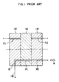
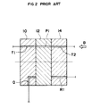
- a sampling valve consists of two fixed elements 10, 14 and a movable element 12 enclosed by the fixed elements 10, 14.
- Fig. 1 and Fig. 2 show two states of the sampling valve.
- the specimen flows in the direction of arrow A, that is, from a pipette 16 to an inlet passage Q, metering (measuring quantity) passage P1, and outlet passage R1, and fills up the metering passage P1 of the movable element 12 (this is called the first state).
- the movable element 12 moves from the first state, it moves to the state shown in Fig.
- the specimen filling up the metering passage P1 in the first state is discharged, and is transferred outside the sampling valve, together with a liquid such as diluent moving in the direction of arrow B from the passage T2 to the passage T1.
- US-A-3,978,888 discloses a more sophisticated version of the above-described sampling valve.
- Its movable element incorporates ten metering passages which, when the movable element is in its first state, are connected in series by relay passages disposed in the fixed elements. Suction is applied to the single outlet passage at the end of the series of metering passages so that ten metered samples are prepared in the ten metering passages. The movable element is then rotated to its second state so that the ten metered samples may be discharged.
- the sampling valve cannot vary the number of metered samples that are prepared.
- a sampling valve for sampling a liquid specimen comprising: two fixed elements; a movable element positioned between and in contact with surfaces of the fixed elements and having a plurality of sample metering passages, the movable element being movable between a first state in which a selected one or combination of the metering passages may be filled with the liquid specimen to form a corresponding number of metered samples of the liquid specimen and a second state in which each metered sample may be discharged from its metering passage and transferred to outside the sampling valve; an inlet passage disposed in one of the fixed elements for supplying the liquid specimen to at least one of the metering passages when the movable element is in its first state; and a plurality of outlet passages disposed in one or both of the fixed elements and arranged to communicate with the metering passages when the movable element is in its first state; wherein the fixed elements include one or more relay passages for connecting together the metering passages when the movable element is in its first state
- the plurality of metering passages are connected in series when the movable element is in its first state.
- the sampling routes coincide, and then the sampling routes diverge after the inlet passage but before the metering passages.
- the sampling routes coincide, and then the sampling routes diverge after the inlet passage and at least one of the metering passages.
- the inlet passage is used to supply the liquid specimen to the sampling valve, and the outlet passages are used to remove excess liquid specimen from the metering passages.
- a pipette is connected to the inlet passage, and suction (aspiration) means is connected to the outlet passages.
- suction aspiration pressure
- the suction means is operated.
- aspiration pressure is applied by the suction means to the outlet passage of a selected one of the sampling routes by using, for example, a changeover valve.
- This aspiration pressure reaches the inlet passage and pipette through the passages of the selected sampling route, and the specimen is aspirated from the pipette.
- the specimen fills up each metering passage of the sampling route, thereby to form a metered sample in each metering passage of the sampling route.
- sampling routes may be selected.
- different metering passages may be filled up.
- the passages in the sampling valve may be arranged to produce the optimum permutations of metered samples to suit a particular purpose.
- the sampling valve When the aspiration of the specimen is over, the sampling valve is moved to its second state, and each sample is discharged and may be transferred to a measurement unit disposed outside the sampling valve. Then, the sampling valve returns to the first state, and each passage is cleaned with a cleaning liquid (syringe liquid) from a cleaning liquid tank.
- a cleaning liquid asyringe liquid
- Each of the embodiments of the sampling valves of the invention as shown in Fig. 3 to Fig. 7, comprises two fixed elements 10, 14 which are stationary, and a movable element 12 positioned between these fixed elements and having a plurality of sample metering passages P.
- the movable element 12 is movable between a first state in which the metering passages P may be filled with liquid specimen and a second state in which the resulting metered sample(s) may be discharged from the metering passages P.
- Each sampling valve also includes:
- a pipette 16 When using the sampling valve, a pipette 16 is connected to the inlet passage Q, and suction (aspiration) means 18 is connected to outlet passages R.
- suction (aspiration) means 18 In the first state, the pipette 16 is dipped in the liquid specimen, and the suction means 18 is operated.
- aspiration pressure is applied by selecting only a certain outlet passage by using, for example, a changeover valve.
- This aspiration pressure reaches the inlet passage Q and pipette 16 through the specified passage within the sampling valve, and the specimen is aspirated from the pipette 16.
- the specimen depending on the connection state of the passages in the sampling valve, flows along a certain sampling route, and each metering passage in that sampling route is filled up. Each sampling route has a particular number of metering passages.
- the sampling valve moves to the second state, and each generally rod-like metered sample is discharged from the sampling valve and is transferred to a measurement unit disposed outside the sampling valve. Then, the sampling valve returns to the first state, and each passage is cleaned with a cleaning liquid (syringe liquid) from a cleaning liquid tank 20.
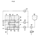
- Fig. 3 shows a valve which has four metering passages, and these metering passages P1, P2, P3, P4 are connected in series, and the three sampling routes mutually partly overlap. More specifically, symbol Q denotes an inlet passage, S1, S2, S3 are relay passages, R1, R2, R3 are outlet passages, and the relay passage S1 connects to the outlet passage R1, and the relay passage S3 connects to the outlet passage R2.
- valve V1 When a valve V1 is open, and valves V2, V3 are closed, by changing over a three-way valve V4 so that aspiration means 18 and valve V1 communicate with each other, the sample flows from pipette 16 through passages Q, P1, R1 (the first sampling route), and is measured quantitatively in the passage P1.
- Fig. 4 shows a valve which has six metering passages, and these metering passages P1, P2, P3, P4, P5, P6 are connected in parallel (partly in series, however, in this embodiment), and three sampling routes are provided in parallel. More specifically, symbol Q denotes an inlet passage, S1, S2, S3, S4, S5 are relay passages, R1, R2, R3 are outlet passages, and the relay passages S1, S4 are connected to the inlet passage Q. Instead, the relay passage S1 may be connected to the inlet passage Q, and the passage S4 connected to passage S1.
- valve V1 When a valve V1 is open, and valves V2, V3 are closed, by changing over a three-way valve V4 so that aspiration means 18 and valve V1 may communicate with each other, the sample flows from a pipette 16 through passages Q, P1, R1 (the first sampling route), and is measured quantitatively in the passage P1.
- Fig. 5 shows a valve which has three metering passages, and these metering passages P1, P2, P3 are connected in a combination of series and parallel, and the three sampling routes partly overlap and are partly parallel.
- symbol Q denotes an inlet passage
- S1, S2 are relay passages
- R1, R2, R3 are outlet passages
- the relay passages S1, S2 are connected to the outlet passage R1.
- the relay passage S1 may be connected to the outlet passage R1, and the passage S2 connected to passage S1.
- valve V1 When a valve V1 is open, and valves V2, V3 are closed, by changing over a three-way valve V4 so that aspiration means 18 and valve V1 may communicate with each other, the sample flows from a pipette 16 through passages Q, P1, R1 (the first sampling route), and is measured quantitatively in the passage P1.
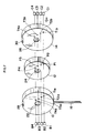
- Fig. 6 and Fig. 7 are views of practical examples of the sampling valve shown in Fig. 3.
- Fig. 6 shows the first state
- Fig. 7 shows the second state.
- the passages are partly omitted. This is for the ease of understanding the drawing and explanation.
- transfer passages T1a, T1b, ..., T4b shown in Fig. 7 are omitted (and are omitted in Figs. 3, 4, 5)
- the passages Q, S1, S2, S3, R1, R2, R3 shown in Fig. 6 are omitted.
- Fixed elements 10, 14 and movable element 12 comprise disc-like bodies. In the center of elements 10, 12, 14, through holes 22, 24, 26 are formed, and a shaft (not shown) passes through the through holes 22, 24, 26. At the upper side of the fixed elements 10, 14, notches 28, 30 are provided, in which a support (not shown) is fitted.
- the movable element 12 is held between the fixed elements 10, 14 and rotates through a specific angle.
- the means for keeping the fixed elements 10, 14 in static state and moving the movable element by a specific extent while contacting the surfaces of the fixed elements is known (see, for example, Japanese Laid-open Patent Hei. 1-138421).
- the mutually contacting surfaces of the elements 10, 12, 14 are planar and polished to an extremely high precision.
- the movable element 12 is, for example, provided with four passages P1, P2, P3, P4 for sampling (measuring quantitatively) the specimen.
- the metering passages P1, P2, P3, P4 are passages penetrating through the movable element 12.
- a pipe-shaped pipette 16 is attached at the lower side of the fixed element 10.
- the pipette 16 communicates with an inlet passage Q having an L-shape and an opening in the polished side surface 10a of the fixed element 10.
- a fine pipe like a syringe needle may be connected through a tube to form a specimen aspiration part.
- the passage Q communicates with the metering passage P1.
- groove-shaped relay passages S1, 53 are provided in the polished surface 14a of the fixed element 14.
- the fixed element 10 includes a loop-shaped relay passage S2 which is formed outside the disc-like body of the fixed element 10.
- the relay passage S1 connects the metering passages P1 and P2, the relay passage S2 connects the metering passages P2 and P3, and the relay passage S3 connects the metering passages P3 and P4. That is, the relay passages S1, S2, S3 connect plural metering passages in series. In portions of the relay passages S1, S3, outlet passages R1, R2, penetrating through the fixed element 14, are provided. In the fixed element 10, an outlet passage R3 connecting to the metering passage P4 is provided. The outlet passage R3 penetrates through the fixed element 10.
- Numeral 18 is aspiration means, which is, for example, a syringe capable of generating an aspiration pressure and discharging the cleaning liquid.
- Numeral 20 is a cleaning liquid (diluent liquid) tank filled with liquid for cleaning (dilution).
- a three-way valve V4 connects the aspiration means 18 to the sampling valve or the cleaning liquid tank.
- Two-way valves V1, V2, V3 are disposed between the syringe 18 and outlet passages R1, R2, R3, and select the route.
- the cleaning liquid is also used as diluent liquid.
- the first sampling route has the inlet passage Q as the inlet and outlet passage R1 as the outlet.
- the second sampling route has the inlet passage Q as the inlet and the outlet passage R2 as the outlet.
- the third sampling route has the inlet passage Q as the inlet and the outlet passage R3 as the outlet.
- diluent liquid discharge means C1, C2, C3, C4 When diluent liquid discharge means C1, C2, C3, C4 are activated, a specific volume of diluent liquid is supplied in the direction of the arrow to each transfer passage T1b, T2b, T3b, T4b.
- the measured samples in the passages P1, P2, P3, P4 pass along the passages T1a, T2a, T3a, T4a and into measurement units B1, B2, B3, B4 together with the diluent liquid.
- the diluent liquid discharge means operates in accordance with the selected sampling route. That is, when the first sampling route is selected (a sample is determined quantitatively in the passage P1 only), only the diluent liquid discharge means C1 is activated.
- the diluent liquid discharge means C1, C2, C3 are activated.
- the third sampling route is selected (four samples are determined quantitatively in the passages P1, P2, P3, P4), all diluent liquid discharge means C1, C2, C3, C4 are activated.
- Fig. 6 From the second state of Fig. 7, the movable element 12 reversely rotates by a specific angle to return to the first state of Fig. 6. Cleaning is similar to the sample transfer described above, because the passages are cleaned according to the selected sampling route. That is, when the first sampling route is selected (specimen is remaining in the passages Q, R1), only the valve V1 is opened and the aspiration means 18 acts as aspiration and cleaning means. When the second sampling route is selected (specimen is remaining in the passages Q, S1, S2, R2), only the valve V2 is opened. When the third sampling route is selected (specimen is remaining in the passages Q, S1, S2, S3, R3), only the valve V3 is opened.
- valves V1, V2 are opened and closed alternately repeatedly (however, the opening time of the valve V1 should be set longer).
- the valves V1, V2, V3 are alternately opened and closed repeatedly (however, the opening time of the valve V2 should be set longer than that of the valves V1, V3 in the case of second sampling route, and the opening time of the valve V3 should be set longer than that of the valves V1, V2 in the case of third sampling route).
- various other valve settings may be considered and may be properly selected depending on the actual configuration of the apparatus.
- the embodiments of the invention have the following characteristics.
Landscapes
- Physics & Mathematics (AREA)
- General Physics & Mathematics (AREA)
- Fluid Mechanics (AREA)
- Analytical Chemistry (AREA)
- Life Sciences & Earth Sciences (AREA)
- Chemical & Material Sciences (AREA)
- Health & Medical Sciences (AREA)
- Biochemistry (AREA)
- General Health & Medical Sciences (AREA)
- Immunology (AREA)
- Pathology (AREA)
- Sampling And Sample Adjustment (AREA)
- Automatic Analysis And Handling Materials Therefor (AREA)
- Sliding Valves (AREA)
- Investigating Or Analysing Biological Materials (AREA)
Claims (7)
- Vanne d'échantillonnage pour échantillonner un spécimen de liquide, comprenant :deux éléments fixes (10, 14) ;un élément mobile (12) positionné entre les surfaces des éléments fixes et en contact avec lesdites surfaces et comportant une pluralité de passages de mesure d'échantillons (P), l'élément mobile (12) étant adapté à un déplacement entre une première condition dans laquelle un passage de mesure ou un ensemble de passages de mesure sélectionnés (P) peuvent être remplis du spécimen liquide pour former un nombre correspondant d'échantillons de mesure de spécimen de liquide et une seconde condition dans laquelle chaque échantillon mesuré peut être déchargé de son passage de mesure et transféré jusqu'à l'extérieur de la vanne d'échantillonnage ;un passage d'entrée (Q) disposé dans un des éléments fixes pour distribuer le spécimen de liquide à au moins un des passages de mesure lorsque l'élément mobile (12) se trouve dans sa première condition ; etune pluralité de passages de sortie (R) disposés dans un des éléments fixes (10, 14), ou dans les deux éléments, et agencés pour communiquer avec les passages de mesure lorsque l'élément mobile (12) se trouve dans sa première condition ;dans laquelle les éléments fixes (10, 14) comprennent un ou plusieurs passages de relais (S) pour relier les passages de mesure (P) les uns aux autres lorsque l'élément mobile (12) se trouve dans sa première condition ; etdans laquelle les passages d'entrée, de mesure, de relais et de sortie (Q, P, S, R) sont agencés, lorsque l'élément mobile (12) se trouve dans sa première condition, pour former une pluralité de voies d'échantillonnage comportant chacune un passage ou un ensemble de passages de mesure (P) respectifs.
- Vanne d'échantillonnage selon la revendication 1, dans laquelle la pluralité de passages de mesure (P) sont reliés en série lorsque l'élément mobile (12) se trouve dans sa première condition.
- Vanne d'échantillonnage selon la revendication 1, dans laquelle les voies d'échantillonnage coïncident initialement, puis les voies d'échantillonnage divergent après le passage d'entrée (Q) mais avant les passages de mesure (P).
- Vanne d'échantillonnage selon la revendication 1, dans laquelle les voies d'échantillonnage coïncident initialement, puis les voies d'échantillonnage divergent après le passage d'entrée (Q) et au moins d'un des passages de mesure (P).
- Vanne d'échantillonnage selon la revendication 2, dans laquelle les voies d'échantillonnage comprennent une première voie d'échantillonnage qui comprend un (P1) des passages de mesure (P), une deuxième voie d'échantillonnage qui comprend trois (P1 à P3) des passages de mesure (P) et une troisième voie d'échantillonnage qui comprend quatre (P1 à P4) des passages de mesure (P).
- Vanne d'échantillonnage selon la revendication 3, dans laquelle les voies d'échantillonnage comprennent une première voie d'échantillonnage qui comprend un (P1) des passages de mesure (P), une deuxième voie d'échantillonnage qui comprend deux (P5, P6) des passages de mesure (P) et une troisième voie d'échantillonnage qui comprend trois (P2 à P4) des passages de mesure (P).
- Vanne d'échantillonnage selon la revendication 4, dans laquelle les voies d'échantillonnage comprennent une première voie d'échantillonnage qui comprend un (P1) des passages de mesure (P), une deuxième voie d'échantillonnage qui comprend ledit un (P1) des passages de mesure et un deuxième (P2) des passages de mesure (P) et une troisième voie d'échantillonnage qui comprend ledit un (P1) des passages de mesure et un troisième (P3) des passages de mesure (P).
Applications Claiming Priority (2)
| Application Number | Priority Date | Filing Date | Title |
|---|---|---|---|
| JP03331283A JP3130608B2 (ja) | 1991-11-20 | 1991-11-20 | サンプリングバルブ |
| JP331283/91 | 1991-11-20 |
Publications (2)
| Publication Number | Publication Date |
|---|---|
| EP0545560A1 EP0545560A1 (fr) | 1993-06-09 |
| EP0545560B1 true EP0545560B1 (fr) | 1998-01-21 |
Family
ID=18241958
Family Applications (1)
| Application Number | Title | Priority Date | Filing Date |
|---|---|---|---|
| EP92310206A Expired - Lifetime EP0545560B1 (fr) | 1991-11-20 | 1992-11-06 | Vanne pour prélèvement des échantillons |
Country Status (6)
| Country | Link |
|---|---|
| US (1) | US5390552A (fr) |
| EP (1) | EP0545560B1 (fr) |
| JP (1) | JP3130608B2 (fr) |
| AU (1) | AU646982B2 (fr) |
| CA (1) | CA2079436C (fr) |
| DE (1) | DE69224169T2 (fr) |
Cited By (1)
| Publication number | Priority date | Publication date | Assignee | Title |
|---|---|---|---|---|
| WO2026003363A1 (fr) * | 2024-06-28 | 2026-01-02 | Thermo Fisher Scientific (Bremen) Gmbh | Ensemble valve pour système analytique |
Families Citing this family (20)
| Publication number | Priority date | Publication date | Assignee | Title |
|---|---|---|---|---|
| US5697899A (en) * | 1995-02-07 | 1997-12-16 | Gensia | Feedback controlled drug delivery system |
| DE19532759B4 (de) * | 1995-09-05 | 2004-07-01 | Rexroth Star Gmbh | Linearführungseinheit |
| TW308536B (en) * | 1995-12-21 | 1997-06-21 | Toa Medical Electronics | Sampling valve |
| US6012487A (en) * | 1997-03-10 | 2000-01-11 | Brian A. Hauck | Prime purge injection valve or multi-route selections valve |
| FR2777349B1 (fr) * | 1998-04-08 | 2000-06-23 | Hycel Diagnostics | Dispositifs et procedes de prelevement de fluides a partir de l'un ou l'autre de deux moyens de prelevement pour un appareil de mesure cytobiologique |
| MY125337A (en) | 1999-06-07 | 2006-07-31 | Failsafe Metering International Ltd | A metering device |
| JP2001173820A (ja) | 1999-12-20 | 2001-06-29 | Fuji Photo Film Co Ltd | バルブ、試料抜き出し装置及び添加装置 |
| DE10013528C1 (de) * | 2000-03-20 | 2001-09-20 | Brand Gmbh & Co Kg | Dosiervorrichtung für insbesondere zähflüsige Flüssigkeiten |
| US6890489B2 (en) * | 2000-04-26 | 2005-05-10 | Rheodyne, L.P. | Mass rate attenuator |
| US6632404B1 (en) * | 2000-08-02 | 2003-10-14 | Symyx Technologies, Inc. | Automatically actuated parallel sample injector valve |
| US6872361B2 (en) * | 2001-06-28 | 2005-03-29 | Coulter International Corp. | Dual pad liquid shear valve assembly |
| US6662826B1 (en) | 2002-10-07 | 2003-12-16 | Abbott Laboratories | Liquid metering and transfer valve assembly with port switch |
| US7661326B2 (en) * | 2006-10-26 | 2010-02-16 | Beckman Coulter, Inc. | Apparatus for aspirating and dispensing liquids in an automated analyzer |
| JP2008175810A (ja) * | 2006-12-19 | 2008-07-31 | Ngk Insulators Ltd | 分析用カートリッジ及び吸光度測定装置 |
| JP2007255717A (ja) * | 2007-06-25 | 2007-10-04 | Toshiba Corp | 化学分析装置 |
| JP5162177B2 (ja) * | 2007-07-31 | 2013-03-13 | シスメックス株式会社 | 粒子分析装置及び粒子分析方法 |
| FR2924804B1 (fr) * | 2007-12-07 | 2012-03-02 | Horiba Abx Sas | Vanne d'echantillonnage multi-positions. |
| WO2010083147A1 (fr) | 2009-01-14 | 2010-07-22 | Waters Technologies Corporation | Soupape rotative |
| JP6114038B2 (ja) * | 2013-01-10 | 2017-04-12 | 凸版印刷株式会社 | 包装容器及びパッケージ商品 |
| EP3376220A4 (fr) * | 2015-11-13 | 2018-11-21 | Alps Electric Co., Ltd. | Structure de trajet d'écoulement et dispositif de mesure pour liquide à mesurer |
Family Cites Families (19)
| Publication number | Priority date | Publication date | Assignee | Title |
|---|---|---|---|---|
| GB1354486A (en) * | 1970-05-20 | 1974-06-05 | Unilever Ltd | Plate valve |
| US3978888A (en) * | 1972-08-15 | 1976-09-07 | Nihon Denshi Kabushiki Kaisha | Rotary measuring valve |
| US3885439A (en) * | 1973-10-24 | 1975-05-27 | Hoffmann La Roche | Rotating sampling valve |
| US3964513A (en) * | 1975-04-08 | 1976-06-22 | Hoffmann-La Roche Inc. | Rotating sampling valve |
| IL47353A0 (en) * | 1975-05-26 | 1975-08-31 | Israel Atomic Energy Comm | High precision fluid flow valve |
| US4152391A (en) * | 1977-12-16 | 1979-05-01 | Coulter Electronics, Inc. | Liquid transfer valve |
| US4445391A (en) * | 1981-10-19 | 1984-05-01 | Coulter Electronics, Inc. | Liquid metering and transfer valve assembly |
| US4507977A (en) * | 1981-10-19 | 1985-04-02 | Coulter Electronics, Inc. | Liquid metering and transfer valve assembly |
| US4506558A (en) * | 1983-03-03 | 1985-03-26 | Rheodyne Incorporated | Injector with minimal flow-interrupt transient |
| CH674580A5 (fr) * | 1983-10-06 | 1990-06-15 | Contraves Ag | |
| US4625569A (en) * | 1984-01-17 | 1986-12-02 | Toyo Soda Manufacturing Co., Ltd. | Liquid injection device |
| US4726237A (en) * | 1985-06-19 | 1988-02-23 | Sequoia-Turner Corporation | Fluid metering apparatus and method |
| US4702889A (en) * | 1986-01-16 | 1987-10-27 | Coulter Electronics Inc. | Liquid sampling valve |
| US4822569A (en) * | 1986-06-09 | 1989-04-18 | Fisher Scientific Company | Rotary shear valve with cleaning feature and method of using same |
| US4896546A (en) * | 1987-10-26 | 1990-01-30 | Coulter Electronics, Inc. | Liquid metering and transfer valve assembly |
| US4957008A (en) * | 1988-12-28 | 1990-09-18 | Coulter Electronics, Inc. | Fluid sampling and transfer valve assembly |
| US4948565A (en) * | 1989-04-25 | 1990-08-14 | Fisher Scientific Company | Analytical system |
| US5207109A (en) * | 1991-02-07 | 1993-05-04 | Rheodyne, Inc. | Internal-external sample injector |
| JPH04120358U (ja) * | 1991-04-12 | 1992-10-28 | 東亜医用電子株式会社 | サンプリングバルブ |
-
1991
- 1991-11-20 JP JP03331283A patent/JP3130608B2/ja not_active Expired - Fee Related
-
1992
- 1992-10-30 US US07/969,574 patent/US5390552A/en not_active Expired - Fee Related
- 1992-11-05 AU AU28179/92A patent/AU646982B2/en not_active Ceased
- 1992-11-06 EP EP92310206A patent/EP0545560B1/fr not_active Expired - Lifetime
- 1992-11-06 DE DE69224169T patent/DE69224169T2/de not_active Expired - Fee Related
- 1992-11-18 CA CA002079436A patent/CA2079436C/fr not_active Expired - Fee Related
Cited By (1)
| Publication number | Priority date | Publication date | Assignee | Title |
|---|---|---|---|---|
| WO2026003363A1 (fr) * | 2024-06-28 | 2026-01-02 | Thermo Fisher Scientific (Bremen) Gmbh | Ensemble valve pour système analytique |
Also Published As
| Publication number | Publication date |
|---|---|
| DE69224169T2 (de) | 1998-05-07 |
| US5390552A (en) | 1995-02-21 |
| JPH05141549A (ja) | 1993-06-08 |
| CA2079436A1 (fr) | 1993-05-21 |
| DE69224169D1 (de) | 1998-02-26 |
| AU646982B2 (en) | 1994-03-10 |
| EP0545560A1 (fr) | 1993-06-09 |
| AU2817992A (en) | 1993-05-27 |
| JP3130608B2 (ja) | 2001-01-31 |
| CA2079436C (fr) | 2001-11-27 |
Similar Documents
| Publication | Publication Date | Title |
|---|---|---|
| EP0545560B1 (fr) | Vanne pour prélèvement des échantillons | |
| US4957008A (en) | Fluid sampling and transfer valve assembly | |
| US5367912A (en) | Apparatus for analyzing liquid specimen | |
| US8623297B2 (en) | Device for the preparation and fractioned dispensing of fluid samples, dispensing system including such device and related method | |
| JP5213269B2 (ja) | 自動化分析器において液体を吸引し分配する装置 | |
| EP0500506A1 (fr) | Appareil pour immunoessais | |
| JPS58181110A (ja) | マルチプログラマブルピンチバルブモジユ−ル | |
| JP2002506989A (ja) | 流体を精確な少量に分配する電子装置 | |
| JP3834902B2 (ja) | 試料導入方法 | |
| US5073343A (en) | Apparatus for measuring a liquid specimen | |
| CN101925822B (zh) | 多位置采样阀 | |
| JPH05505030A (ja) | 液体測定及び移送弁組立体 | |
| EP0253519B1 (fr) | Dispositif de manipulation d'échantillons | |
| US7563410B2 (en) | Solid phase extraction apparatus and method | |
| JPS63286770A (ja) | 医療検査用液体分析装置の分注ノズルと定量分注ポンプ | |
| EP1364198A1 (fr) | Procede destine au test d'echantillons liquides, unite de test utilisant ce procede, et systeme comprenant de telles unites de test | |
| JPH028746A (ja) | 分析装置 | |
| JP3164406B2 (ja) | 選択的液体分注装置および選択的液体分注方法 | |
| JP2519488B2 (ja) | 試料定量弁 | |
| JPH019013Y2 (fr) | ||
| JPH06241332A (ja) | サンプリングバルブ | |
| FI57850B (fi) | Foerfarande och anordning foer hantering av vaetskesatser | |
| EP0564439A2 (fr) | Dispositif d'alimentation sélective des fluides dans un analyseur | |
| JPS60177267A (ja) | 自動分析装置 | |
| JP2001324510A (ja) | 吐出容量可変液体分注装置 |
Legal Events
| Date | Code | Title | Description |
|---|---|---|---|
| PUAI | Public reference made under article 153(3) epc to a published international application that has entered the european phase |
Free format text: ORIGINAL CODE: 0009012 |
|
| AK | Designated contracting states |
Kind code of ref document: A1 Designated state(s): DE FR GB IT NL |
|
| 17P | Request for examination filed |
Effective date: 19931118 |
|
| 17Q | First examination report despatched |
Effective date: 19940808 |
|
| GRAG | Despatch of communication of intention to grant |
Free format text: ORIGINAL CODE: EPIDOS AGRA |
|
| GRAH | Despatch of communication of intention to grant a patent |
Free format text: ORIGINAL CODE: EPIDOS IGRA |
|
| GRAH | Despatch of communication of intention to grant a patent |
Free format text: ORIGINAL CODE: EPIDOS IGRA |
|
| GRAA | (expected) grant |
Free format text: ORIGINAL CODE: 0009210 |
|
| AK | Designated contracting states |
Kind code of ref document: B1 Designated state(s): DE FR GB IT NL |
|
| PG25 | Lapsed in a contracting state [announced via postgrant information from national office to epo] |
Ref country code: NL Free format text: LAPSE BECAUSE OF FAILURE TO SUBMIT A TRANSLATION OF THE DESCRIPTION OR TO PAY THE FEE WITHIN THE PRESCRIBED TIME-LIMIT Effective date: 19980121 Ref country code: IT Free format text: LAPSE BECAUSE OF FAILURE TO SUBMIT A TRANSLATION OF THE DESCRIPTION OR TO PAY THE FEE WITHIN THE PRE;WARNING: LAPSES OF ITALIAN PATENTS WITH EFFECTIVE DATE BEFORE 2007 MAY HAVE OCCURRED AT ANY TIME BEFORE 2007. THE CORRECT EFFECTIVE DATE MAY BE DIFFERENT FROM THE ONE RECORDED.SCRIBED TIME-LIMIT Effective date: 19980121 |
|
| REF | Corresponds to: |
Ref document number: 69224169 Country of ref document: DE Date of ref document: 19980226 |
|
| ET | Fr: translation filed | ||
| NLV1 | Nl: lapsed or annulled due to failure to fulfill the requirements of art. 29p and 29m of the patents act | ||
| PLBE | No opposition filed within time limit |
Free format text: ORIGINAL CODE: 0009261 |
|
| 26N | No opposition filed | ||
| REG | Reference to a national code |
Ref country code: GB Ref legal event code: IF02 |
|
| PGFP | Annual fee paid to national office [announced via postgrant information from national office to epo] |
Ref country code: GB Payment date: 20021106 Year of fee payment: 11 |
|
| PGFP | Annual fee paid to national office [announced via postgrant information from national office to epo] |
Ref country code: DE Payment date: 20021107 Year of fee payment: 11 |
|
| PGFP | Annual fee paid to national office [announced via postgrant information from national office to epo] |
Ref country code: FR Payment date: 20021108 Year of fee payment: 11 |
|
| PG25 | Lapsed in a contracting state [announced via postgrant information from national office to epo] |
Ref country code: GB Free format text: LAPSE BECAUSE OF NON-PAYMENT OF DUE FEES Effective date: 20031106 |
|
| PG25 | Lapsed in a contracting state [announced via postgrant information from national office to epo] |
Ref country code: DE Free format text: LAPSE BECAUSE OF NON-PAYMENT OF DUE FEES Effective date: 20040602 |
|
| GBPC | Gb: european patent ceased through non-payment of renewal fee |
Effective date: 20031106 |
|
| PG25 | Lapsed in a contracting state [announced via postgrant information from national office to epo] |
Ref country code: FR Free format text: LAPSE BECAUSE OF NON-PAYMENT OF DUE FEES Effective date: 20040730 |
|
| REG | Reference to a national code |
Ref country code: FR Ref legal event code: ST |