EP0545680B1 - Fussbodentürschliesser - Google Patents
Fussbodentürschliesser Download PDFInfo
- Publication number
- EP0545680B1 EP0545680B1 EP92310989A EP92310989A EP0545680B1 EP 0545680 B1 EP0545680 B1 EP 0545680B1 EP 92310989 A EP92310989 A EP 92310989A EP 92310989 A EP92310989 A EP 92310989A EP 0545680 B1 EP0545680 B1 EP 0545680B1
- Authority
- EP
- European Patent Office
- Prior art keywords
- piston
- opening
- diaphragm
- plug
- body case
- Prior art date
- Legal status (The legal status is an assumption and is not a legal conclusion. Google has not performed a legal analysis and makes no representation as to the accuracy of the status listed.)
- Expired - Lifetime
Links
Images
Classifications
-
- F—MECHANICAL ENGINEERING; LIGHTING; HEATING; WEAPONS; BLASTING
- F16—ENGINEERING ELEMENTS AND UNITS; GENERAL MEASURES FOR PRODUCING AND MAINTAINING EFFECTIVE FUNCTIONING OF MACHINES OR INSTALLATIONS; THERMAL INSULATION IN GENERAL
- F16F—SPRINGS; SHOCK-ABSORBERS; MEANS FOR DAMPING VIBRATION
- F16F9/00—Springs, vibration-dampers, shock-absorbers, or similarly-constructed movement-dampers using a fluid or the equivalent as damping medium
- F16F9/32—Details
- F16F9/50—Special means providing automatic damping adjustment, i.e. self-adjustment of damping by particular sliding movements of a valve element, other than flexions or displacement of valve discs; Special means providing self-adjustment of spring characteristics
- F16F9/52—Special means providing automatic damping adjustment, i.e. self-adjustment of damping by particular sliding movements of a valve element, other than flexions or displacement of valve discs; Special means providing self-adjustment of spring characteristics in case of change of temperature
-
- E—FIXED CONSTRUCTIONS
- E05—LOCKS; KEYS; WINDOW OR DOOR FITTINGS; SAFES
- E05F—DEVICES FOR MOVING WINGS INTO OPEN OR CLOSED POSITION; CHECKS FOR WINGS; WING FITTINGS NOT OTHERWISE PROVIDED FOR, CONCERNED WITH THE FUNCTIONING OF THE WING
- E05F3/00—Closers or openers with braking devices, e.g. checks; Construction of pneumatic or liquid braking devices
- E05F3/04—Closers or openers with braking devices, e.g. checks; Construction of pneumatic or liquid braking devices with liquid piston brakes
- E05F3/10—Closers or openers with braking devices, e.g. checks; Construction of pneumatic or liquid braking devices with liquid piston brakes with a spring, other than a torsion spring, and a piston, the axes of which are the same or lie in the same direction
- E05F3/104—Closers or openers with braking devices, e.g. checks; Construction of pneumatic or liquid braking devices with liquid piston brakes with a spring, other than a torsion spring, and a piston, the axes of which are the same or lie in the same direction with cam-and-slide transmission between driving shaft and piston within the closer housing
-
- E—FIXED CONSTRUCTIONS
- E05—LOCKS; KEYS; WINDOW OR DOOR FITTINGS; SAFES
- E05F—DEVICES FOR MOVING WINGS INTO OPEN OR CLOSED POSITION; CHECKS FOR WINGS; WING FITTINGS NOT OTHERWISE PROVIDED FOR, CONCERNED WITH THE FUNCTIONING OF THE WING
- E05F3/00—Closers or openers with braking devices, e.g. checks; Construction of pneumatic or liquid braking devices
- E05F3/04—Closers or openers with braking devices, e.g. checks; Construction of pneumatic or liquid braking devices with liquid piston brakes
- E05F3/12—Special devices controlling the circulation of the liquid, e.g. valve arrangement
-
- E—FIXED CONSTRUCTIONS
- E05—LOCKS; KEYS; WINDOW OR DOOR FITTINGS; SAFES
- E05Y—INDEXING SCHEME ASSOCIATED WITH SUBCLASSES E05D AND E05F, RELATING TO CONSTRUCTION ELEMENTS, ELECTRIC CONTROL, POWER SUPPLY, POWER SIGNAL OR TRANSMISSION, USER INTERFACES, MOUNTING OR COUPLING, DETAILS, ACCESSORIES, AUXILIARY OPERATIONS NOT OTHERWISE PROVIDED FOR, APPLICATION THEREOF
- E05Y2800/00—Details, accessories and auxiliary operations not otherwise provided for
-
- E—FIXED CONSTRUCTIONS
- E05—LOCKS; KEYS; WINDOW OR DOOR FITTINGS; SAFES
- E05Y—INDEXING SCHEME ASSOCIATED WITH SUBCLASSES E05D AND E05F, RELATING TO CONSTRUCTION ELEMENTS, ELECTRIC CONTROL, POWER SUPPLY, POWER SIGNAL OR TRANSMISSION, USER INTERFACES, MOUNTING OR COUPLING, DETAILS, ACCESSORIES, AUXILIARY OPERATIONS NOT OTHERWISE PROVIDED FOR, APPLICATION THEREOF
- E05Y2800/00—Details, accessories and auxiliary operations not otherwise provided for
- E05Y2800/40—Physical or chemical protection
- E05Y2800/414—Physical or chemical protection against high or low temperatures
Definitions
- the present invention relates to a floor hinge in which a door opening rotational force of a door is converted into a linear motion, a piston is moved while accumulating a return spring by a door opening action, and the piston is then returned to an original position by the accumulated force of the return spring having a body case in which a piston is slidably accommodated.
- the piston divides a cylinder space in the body case into a piston front chamber and a piston rear chamber.
- An output shaft connected to a door is associated with a rotational motion-linear motion converting mechanism including a cam mechanism, and the open and close movement is transmitted, through the rotational motion-linear motion converting mechanism, to the piston.
- working oil is moved between the piston front and rear chambers.
- US-A-3137888 which is regarded as the closest prior art according to the preamble of claim 1, discloses an overhead door closer with a valve system for equalising pressures to ensure smooth operation of a door at all temperatures.
- DE-A-3320069 shows an oil damper incorporating a flexible membrane.
- a floor hinge having a body case, an output shaft projected from the body case to be connected to a door, and a piston connected to the output shaft through a rotational motion-linear motion converting mechanism (A) for converting rotational motion of the output shaft into linear motion of the piston, the piston being moved reciprocatingly in the body case, and dividing a cylinder space (S) into two first and second piston chambers, working oil being moved between the two first and second piston chambers in response to rotational movement of the output shaft, whereby the body case is provided with an oil pressure absorption means (M) for absorbing increase of oil pressure due to expansion of the working oil, said oil pressure absorption means (M) comprising an opening formed at a position corresponding to either of the two first and second piston chambers in the body case, characterised in that said oil absorption means further comprises an elastic diaphragm for closing said opening and a plug for fastening the diaphragm in the opening, said plug having a cup-like shape to form an air-s
- the floor hinge may be applied to any type of a right swing door, a left swing door and a biparting door.
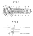
- the floor hinge includes an output shaft 1 connected to the door and serving as a rotary shaft of the door and a main piston 3 connected to the output shaft 1 by a rotational motion-linear motion converting mechanism A which uses a cam mechanism for converting rotational motion of the output shaft (1) into linear motion of the main piston 3.
- the piston 3 divides a cylinder space S formed in a body case 6 into two piston front and rear chambers 4, 5, and is reciprocatingly moved by the rotation of the output shaft 1 in response to the door opening action to thereby compress a return spring 2.
- the piston 3 is returned back to the original position by the returning force of the return spring 2 to thereby transmit the door closing force to the output shaft 1 through the rotational motion-linear motion converting mechanism A.
- the moving speed of the piston 3 during the door closing action is controlled by adjusting a flow rate of the working oil of the piston front chamber 4 to a piston rear chamber 5 through a hydraulic control circuit (not shown).
- the body case 6 is in the form of a longitudinal flat cylindrical shape.
- the body case 6 has, on its right end side, a main piston cylinder 6a which is liquid tightly sealed by a cylinder head 20 and, on its left side, a back check cylinder 6b which is liquid tightly sealed by a back check cylinder head 21.
- the back check cylinder 6b has, on its upper side, an opening which is liquid tightly closed by a lid plate 22 with the output shaft 1 projecting therethrough.
- the main piston 3 is received in the cylinder 6a.
- the back check cylinder 6b receives the back check piston 10 slidably.
- the piston front chamber 4 is defined between the piston 3 and the cylinder head 20.
- the piston rear chamber 5 is in fluid communication with the back check cylinder 6b through a bypass passage (not shown).
- the output shaft 1 is supported by a bearing 28 provided at a bottom of the body case 6 and a bearing 29 provided on the lid plate 22. The output shaft 1 is projected outwardly through the lid plate 22.
- the rotational motion-linear motion converting mechanism A includes a cam mechanism connected to a connecting rod 30 whose front end 30a is loosely inserted into the main piston 3 and whose front end is connected to the main piston 3 through a pin 31.
- the piston 3 has a check valve 32 for only permitting the working oil to flow from the piston rear chamber 5 into the piston front chamber 4 when the door is opened.
- the back check piston 10 has a check valve 35, and is urged by a spring 9 toward the main piston 3.
- the back check piston 10 functions to restrict the door opening motion by abutting the left end of the mechanism A when the door is quickly opened.
- the floor hinge has an air absorption means M for absorbing increase of the working oil accommodated in the cylinder space S in a bottom plate 40 at the bottom of the body case 6.
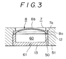
- the bottom plate 40 is provided with an opening 7 as shown in FIGS. 1 and 3.
- the opening 7 has a step portion 7a to form an expanded opening under the step portion 7a.
- the inner wall of the expanded opening has a female screw 50.
- a diaphragm 8 is accommodated in the opening 7 in a state wherein a peripheral portion 8a of the diaphragm 8 is pushed toward the step portion 7a.
- the diaphragm 8 has a thin center portion which is arched spherically inwardly of the body case 6, and the peripheral portion 8a is formed thick in the shape of a ring.
- the diaphragm 8 is made of rubber, and the peripheral portion 8a of the diaphragm 8 is fastened to the step portion 7a by a plug 13 in the shape of a cup through a ring-like packing 12.
- the plug 13 has, at its outer wall, a male screw 51 to mesh with the female screw 50 of the inner wall of the opening 7.
- a groove 61 into which a tool is inserted when the plug 13 is engaged with the opening 7.
- the diaphragm 8 and the plug 13 forms an air-sealed space 60.
- the center portion 8b of the diaphragm 8b is concaved outwardly, and when the oil pressure is decreased in the piston rear chamber 5, the center portion 8b of the diaphragm 8 is returned to a convex shape as shown in FIG. 3. If the floor hinge is subject to sunlight especially during summer time to increase remarkably the temperature of the working oil in the piston rear chamber 5, the working oil is expanded to increase the oil pressure therein. At this time, the center portion 8b of the diaphragm 8 is concaved to compress the air in the space 60 formed with the diaphragm 8 and the plug 13.
- the oil pressure absorption means M may be formed on the front piston chamber 4.
Landscapes
- Engineering & Computer Science (AREA)
- General Engineering & Computer Science (AREA)
- Mechanical Engineering (AREA)
- Closing And Opening Devices For Wings, And Checks For Wings (AREA)
Claims (4)
- Fußboden-Türschließer mit einem Gehäuse (6), einer Ausgangswelle (1), die aus dem Gehäuse (6) zur Verbindung mit einer Tür hervorragt, und einem Kolben (3), der mit der Ausgangswelle (1) über einen Drehbewegung-Linearbewegung-Umsetzungsmechanismus (A) verbunden ist, der die Drehbewegung der Ausgangswelle (1) in eine Linearbewegung des Kolbens (3) umsetzt, wobei der Kolben (3) in dem Gehäuse (6) hin- und herbewegt wird und einen Zylinderraum (S) in eine erste und eine zweite Kolbenkammer (4,5) unterteilt, wobei Arbeitsöl zwischen der ersten und zweiten Kolbenkammer (4,5) in Abhängigkeit von der Drehbewegung der Ausgangswelle (1) bewegt wird, wobei das Gehäuse (6) mit einer Öldruck-Absorptionsvorrichtung (M) versehen ist, um ein Ansteigen des Öldrucks infolge der Ausdehnung des Arbeitsöls zu absorbieren, wobei die Öldruck-Absorptionsvorrichtung (M) eine Öffnung (7) aufweist, die an einer der ersten oder zweiten Kolbenkammer (4,5) entsprechenden Position in dem Gehäuse (6) angeordnet ist, dadurch gekennzeichnet, daß die Öl-Absorptionsvorrichtung des weiteren eine elastische Membran (8) zum Verschließen der Öffnung (7) und einen Stopfen (13) zur Befestigung der Membran (8) in der Öffnung (7) aufweist, wobei der Stopfen (13) eine tassenartige Form zur Bildung eines luftdichten Raumes im Zusammenwirken mit der Membran (8) besitzt und im Schraubeingriff mit der Öffnung (7) steht und wobei die Öffnung (7) mit einem gestuften Abschnitt (7a) versehen ist, an dem ein Umfangsabschnitt (8a) der Membran (8) befestigt ist.
- Fußboden-Türschließer nach Anspruch 1, dadurch gekennzeichnet, daß die Membran (8) aus Gummi besteht.
- Fußboden-Türschließer nach Anspruch 1, dadurch gekennzeichnet, daß der Umfangsabschnitt (8a) in Form eines verdickten Rings ausgebildet ist und an dem gestuften Abschnitt (7a) mittels des Stopfens (13) über eine ringartige Packung (12) befestigt ist.
- Fußboden-Türschließer nach Anspruch 1, dadurch gekennzeichnet, daß der Stopfen (13) eine Bodenwand besitzt, in der eine Nut (61) ausgebildet ist, in die ein Werkzeug eingesetzt wird, wenn der Stopfen (13) mit der Öffnung (7) in Eingriff gebracht wird.
Applications Claiming Priority (2)
| Application Number | Priority Date | Filing Date | Title |
|---|---|---|---|
| JP108963/91 | 1991-02-18 | ||
| JP1991108963U JP2557384Y2 (ja) | 1991-12-06 | 1991-12-06 | フロアーヒンジ |
Publications (2)
| Publication Number | Publication Date |
|---|---|
| EP0545680A1 EP0545680A1 (de) | 1993-06-09 |
| EP0545680B1 true EP0545680B1 (de) | 1994-12-07 |
Family
ID=14498101
Family Applications (1)
| Application Number | Title | Priority Date | Filing Date |
|---|---|---|---|
| EP92310989A Expired - Lifetime EP0545680B1 (de) | 1991-12-06 | 1992-12-02 | Fussbodentürschliesser |
Country Status (3)
| Country | Link |
|---|---|
| EP (1) | EP0545680B1 (de) |
| JP (1) | JP2557384Y2 (de) |
| DE (1) | DE69200831T2 (de) |
Families Citing this family (5)
| Publication number | Priority date | Publication date | Assignee | Title |
|---|---|---|---|---|
| CA2147584C (en) * | 1994-04-25 | 2001-08-14 | Rex H. Lasson | Door closer for the non-fire side of a fire-door safety installation |
| KR100321797B1 (ko) * | 1999-07-09 | 2002-01-31 | 송기덕 | 방수단열기능을 갖는 플로어힌지 및 그 설치방법 |
| KR200267338Y1 (ko) * | 2001-11-21 | 2002-03-09 | 쓰리케이 주식회사 | 플로어 힌지 조립체 |
| DE102009026990A1 (de) * | 2009-06-17 | 2010-12-23 | Geze Gmbh | Ventil für einen Türschließer |
| DE102023208503B4 (de) * | 2023-09-04 | 2026-01-08 | Geze Gmbh | Antrieb für einen Flügel eines Fensters oder einer Tür |
Family Cites Families (3)
| Publication number | Priority date | Publication date | Assignee | Title |
|---|---|---|---|---|
| US3137888A (en) * | 1962-01-11 | 1964-06-23 | Bommer Spring Hinge Co Inc | Concealed overhead door closer |
| US4010829A (en) * | 1974-09-30 | 1977-03-08 | Yamaha, Hatsudoki Kabushiki Kaisha | Hydraulic shock absorber |
| JPS58189843U (ja) * | 1982-06-12 | 1983-12-16 | 株式会社ニフコ | オイル式ダンパ− |
-
1991
- 1991-12-06 JP JP1991108963U patent/JP2557384Y2/ja not_active Expired - Fee Related
-
1992
- 1992-12-02 DE DE69200831T patent/DE69200831T2/de not_active Expired - Fee Related
- 1992-12-02 EP EP92310989A patent/EP0545680B1/de not_active Expired - Lifetime
Also Published As
| Publication number | Publication date |
|---|---|
| EP0545680A1 (de) | 1993-06-09 |
| DE69200831D1 (de) | 1995-01-19 |
| DE69200831T2 (de) | 1995-04-27 |
| JP2557384Y2 (ja) | 1997-12-10 |
| JPH0549985U (ja) | 1993-07-02 |
Similar Documents
| Publication | Publication Date | Title |
|---|---|---|
| US3837166A (en) | Apparatus for transmitting force by hydraulic pressure | |
| US5012551A (en) | Furniture hinge | |
| EP0469697B1 (de) | Hydraulischer Türschliesser | |
| JP3112895B2 (ja) | 中間停止機能および温度補償能力を有するガススプリング | |
| CA2222799C (en) | Pneumatic spring | |
| WO2003102425A3 (en) | Hydraulic dampers with pressure regulated control valve and remote pressure adjustment | |
| US6151753A (en) | Door closer to generate a sudden change in the transmission ratio during the closing phase | |
| EP0409445A1 (de) | Türschliesser | |
| CA2238150A1 (en) | Gas spring with speed regulation | |
| CN112912580A (zh) | 用于机动车的盖的驱动装置 | |
| JP2004116779A (ja) | 長さ調整可能な圧縮バネ | |
| EP0545680A1 (de) | Fussbodentürschliesser | |
| EP0270285A2 (de) | Druckzylinder | |
| CN205559858U (zh) | 调温阀 | |
| EP0891500B1 (de) | Flüssigkeitsdruckfeder | |
| CN107314150A (zh) | 调温阀 | |
| CN205559961U (zh) | 调温阀 | |
| US4653272A (en) | Fluid actuation device with compensation for wear | |
| US4553470A (en) | Assistor for reducing stepping force | |
| US6092632A (en) | Gas spring with temperature compensation | |
| US4102004A (en) | Door closer | |
| EP0545624B1 (de) | Fussbodentürschliesser | |
| EP1186795B1 (de) | Gasfeder mit kontrolliertem Rückzugsverhalten und Einrichtung mit einer solchen Gasfeder | |
| US4075734A (en) | Door closer | |
| CN218644103U (zh) | 一种液压地弹簧 |
Legal Events
| Date | Code | Title | Description |
|---|---|---|---|
| PUAI | Public reference made under article 153(3) epc to a published international application that has entered the european phase |
Free format text: ORIGINAL CODE: 0009012 |
|
| AK | Designated contracting states |
Kind code of ref document: A1 Designated state(s): DE FR GB |
|
| 17P | Request for examination filed |
Effective date: 19930707 |
|
| 17Q | First examination report despatched |
Effective date: 19930906 |
|
| GRAA | (expected) grant |
Free format text: ORIGINAL CODE: 0009210 |
|
| AK | Designated contracting states |
Kind code of ref document: B1 Designated state(s): DE FR GB |
|
| REF | Corresponds to: |
Ref document number: 69200831 Country of ref document: DE Date of ref document: 19950119 |
|
| ET | Fr: translation filed | ||
| PLBE | No opposition filed within time limit |
Free format text: ORIGINAL CODE: 0009261 |
|
| 26N | No opposition filed | ||
| REG | Reference to a national code |
Ref country code: GB Ref legal event code: 746 Effective date: 19980702 |
|
| REG | Reference to a national code |
Ref country code: FR Ref legal event code: D6 |
|
| PGFP | Annual fee paid to national office [announced via postgrant information from national office to epo] |
Ref country code: GB Payment date: 20001123 Year of fee payment: 9 |
|
| PGFP | Annual fee paid to national office [announced via postgrant information from national office to epo] |
Ref country code: FR Payment date: 20001222 Year of fee payment: 9 |
|
| PGFP | Annual fee paid to national office [announced via postgrant information from national office to epo] |
Ref country code: DE Payment date: 20001223 Year of fee payment: 9 |
|
| PG25 | Lapsed in a contracting state [announced via postgrant information from national office to epo] |
Ref country code: GB Free format text: LAPSE BECAUSE OF NON-PAYMENT OF DUE FEES Effective date: 20011202 |
|
| REG | Reference to a national code |
Ref country code: GB Ref legal event code: IF02 |
|
| PG25 | Lapsed in a contracting state [announced via postgrant information from national office to epo] |
Ref country code: DE Free format text: LAPSE BECAUSE OF NON-PAYMENT OF DUE FEES Effective date: 20020702 |
|
| GBPC | Gb: european patent ceased through non-payment of renewal fee |
Effective date: 20011202 |
|
| PG25 | Lapsed in a contracting state [announced via postgrant information from national office to epo] |
Ref country code: FR Free format text: LAPSE BECAUSE OF NON-PAYMENT OF DUE FEES Effective date: 20020830 |
|
| REG | Reference to a national code |
Ref country code: FR Ref legal event code: ST |