EP0545681B1 - Bandage pneumatique de sécurité - Google Patents
Bandage pneumatique de sécurité Download PDFInfo
- Publication number
- EP0545681B1 EP0545681B1 EP19920310990 EP92310990A EP0545681B1 EP 0545681 B1 EP0545681 B1 EP 0545681B1 EP 19920310990 EP19920310990 EP 19920310990 EP 92310990 A EP92310990 A EP 92310990A EP 0545681 B1 EP0545681 B1 EP 0545681B1
- Authority
- EP
- European Patent Office
- Prior art keywords
- tyre
- bead
- total thickness
- rubber layer
- point
- Prior art date
- Legal status (The legal status is an assumption and is not a legal conclusion. Google has not performed a legal analysis and makes no representation as to the accuracy of the status listed.)
- Expired - Lifetime
Links
Images


Classifications
-
- B—PERFORMING OPERATIONS; TRANSPORTING
- B60—VEHICLES IN GENERAL
- B60C—VEHICLE TYRES; TYRE INFLATION; TYRE CHANGING; CONNECTING VALVES TO INFLATABLE ELASTIC BODIES IN GENERAL; DEVICES OR ARRANGEMENTS RELATED TO TYRES
- B60C13/00—Tyre sidewalls; Protecting, decorating, marking, or the like, thereof
-
- B—PERFORMING OPERATIONS; TRANSPORTING
- B60—VEHICLES IN GENERAL
- B60C—VEHICLE TYRES; TYRE INFLATION; TYRE CHANGING; CONNECTING VALVES TO INFLATABLE ELASTIC BODIES IN GENERAL; DEVICES OR ARRANGEMENTS RELATED TO TYRES
- B60C17/00—Tyres characterised by means enabling restricted operation in damaged or deflated condition; Accessories therefor
- B60C17/0009—Tyres characterised by means enabling restricted operation in damaged or deflated condition; Accessories therefor comprising sidewall rubber inserts, e.g. crescent shaped inserts
-
- B—PERFORMING OPERATIONS; TRANSPORTING
- B60—VEHICLES IN GENERAL
- B60C—VEHICLE TYRES; TYRE INFLATION; TYRE CHANGING; CONNECTING VALVES TO INFLATABLE ELASTIC BODIES IN GENERAL; DEVICES OR ARRANGEMENTS RELATED TO TYRES
- B60C13/00—Tyre sidewalls; Protecting, decorating, marking, or the like, thereof
- B60C2013/005—Physical properties of the sidewall rubber
- B60C2013/007—Thickness
Definitions
- the present invention relates to a pneumatic tyre, more particularly a run flat tyre of which run flat performance is improved without sacrificing high speed durability and steering stability so as to run safely for a long distance.
- the thickness of the bead portion increases, and the bead rigidity is increased.
- a crescent-shaped three-layered rubber structure of which the radially inner edge is terminated in the sidewall portion above the rim flange top, is disposed axially inside the carcass, and the sidewall thickness decreases from the maximum tyre section width point towards the tyre shoulder.
- Such a tyre is effective in providing run flat performance.
- a rim specifically designed for the tyre must be used. Therefore, tyre users are restricted in their freedom of rim selection, which is commercially not preferable. It is preferable that a tyre can be mounted on a normal rim rather than on such a special rim.
- An object of the present invention is therefore, to provide a pneumatic safety tyre suitable for high speed sport use which is improved in run flat performance without sacrificing high speed running performance.
- Another object of the present invention is to provide a pneumatic safety tyre devoid of a special bead toe, which can be mounted on a normal rim.
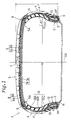
- a pneumatic tyre comprises a tread portion, a pair of axially spaced bead portions, a pair of sidewalls extending between tread edges and the bead portions, a pair of bead cores disposed one in each bead portion, a carcass extending between the bead portions through the tread portion and sidewalls, and a belt disposed radially outside the carcass and extending across the tread width, characterised in that each sidewall is provided axially inside the carcass with an inside sidewall rubber layer (10), the inside sidewall rubber layer extending radially inwardly to the bead portion and radially outwardly into the tread portion along the convexly curved inner surface of the carcass, the total thickness of the tyre measured from the outer surface to the inner surface of the tyre being such that the total thickness (TA) is substantially constant in a region (S), defined as the region extending between a maximum width point (A) at which the width of the ty
- a pneumatic safety tyre 1 of the present invention is designed for a high performance sport car, and the tyre size is 255/45ZR17.
- the tyre 1 is a run flat tyre to be mounted on an AH type rim (a humped rim) or a normal rim (no hump and no groove) as a regular rim R.
- the tyre 1 comprises a tread portion 5, a pair of axially spaced bead portions 3, a pair of sidewalls extending between the tread edges and the bead portions 3, a pair of bead cores 2 each disposed in each of the bead portions 3, a toroidal carcass 6 extending between the bead portions 3, and a belt disposed radially outside the carcass 6 and inside a rubber tread.
- the aspect ratio of the tyre 1, namely, the ratio H/W of the tyre section height H to the maximum tyre width W is less than 0.5 (50%), in this embodiment 0.45 (45%).
- the carcass 6 comprises two plies 6A and 6B of cords extending between the bead portions 3 and turned up around the bead cores 2 from the axially inside to the outside thereof to form two turned up portions and a main portion.
- the carcass cords in each of the carcass plies 6A and 6B are arranged radially at an angle of 60 to 90 degrees with respect to the tyre equator CO.
- steel cords or organic fibre cords e.g. rayon, polyester, nylon, aromatic polyamide or the like can be used.
- the carcass 6 is convexly curved, and the inner surface thereof is also convexly curved both outwards from the tyre air chamber.
- the belt in this embodiment comprises a breaker belt 7 and a band belt 8.
- the breaker belt 7 comprises a radially inner wide ply 7A disposed on the radially outside of the carcass 6 and an radially outer narrow ply 7B disposed on the radially outside of the inner wide ply 7A, each extending across the entire width of the tread portion.
- Each of the belt plies 7A and 7B is composed of parallel cords laid at a relatively small angle with respect to the tyre equator CO so as to cross each other.
- steel cords or high elastic modulus organic cords e.g. aromatic polyamide are used.
- the band belt 8 comprises a radially inner ply 8A and a radially outer ply 8B.
- the inner ply 8A comprises a pair of axially spaced parts disposed on the radially outside of the breaker belt 7.
- Each part has an axially outer edge extending axially outwardly over one of the edges of the breaker belt 7, and an axially inner edge terminated at an axial distance, from the tyre equator CO, of about 1/4 of the tread width.
- the outer ply 8B extends across the entire width of the tread portion so as to cover the radially outer side of the inner ply 8A and a central part of the radially outer side of the belt layer 7, and the edge thereof are substantially aligned with the axially outer edges of the inner ply 8A.
- organic fibre cords e.g. rayon, nylon, polyester or the like are used.
- a breaker cushion 9 made of a soft rubber compound is disposed between the edge of the breaker belt 7 and the carcass 6.
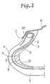
- an inside sidewall rubber layer 10 is disposed on the inside of the carcass 6, and an outside sidewall rubber layer 11 is disposed on the outside of the carcass 6.
- the outside sidewall rubber layer 11 has a JIS A hardness of 55 to 65.
- the inside sidewall rubber layer 10 decreases in thickness towards its radially inner and outer edges from its central part, and accordingly the cross sectional shape thereof is generally a crescent shape.
- the radially outer edge extends into the tread portion 5 axially inwardly beyond the belt edge and is terminated beneath the belt in the tread shoulder region 5A.
- the radially inner edge extends into the bead portion 3 and is terminated axially inside the bead core 2 so as to increase the thickness of the bead portion and to thereby increase the bead rigidity.
- the tyre sidewall 4 Under deflated conditions, the tyre sidewall 4 is liable to be bent around the radially outer edge of its wheel rim flange RF, and accordingly a separation failure is liable to occur in such region. Therefore, the tyre thickness around the rim flange edge is increased to withstand such bending deformation.
- the inside sidewall rubber layer 10 has a double-layered structure composed of an axially outer layer A2 in direct contact with the inside of the carcass and an axially inner layer A1.
- the axially outer layer A2 forms most of the inside sidewall rubber layer 10 and extends between the above-mentioned radially outer and inner edges the layer 10.
- the axially inner layer A1 is soft and very thin.
- the axially inner layer A1 is disposed on the inner surface of the axially outer layer A2 so as to extend between a position substantially corresponding to the radially outer edge of the bead apex in the radial direction and a position substantially corresponding to the axially outer edge of the belt in the axial direction and thereby to cover only the central part of the inner surface.
- the axially inner layer A1 has a JIS A hardness of 50 to 70 and a 100% modulus of 10 to 30 kgf/cm2, and the thickness thereof is about 1 mm.
- the axially outer layer A2 has a JIS A hardness of 70 to 90 and a 100% modulus of 30 to 70 kgf/cm2.
- the axially outer layer A2 is harder than the outside sidewall rubber layer 11.
- the inner layer A1 is disposed, in the region within which the compressive stress under run flat condition is greatest, in order to mitigate the compressive stress.
- the inner layer A1 prevents the inner surface from being cracked and durability is improved.
- the total thickness of the tyre measured from the outer surface to the inner surface of the tyre is specifically defined.
- the total thickness TA of the sidewall portion 4 is substantially constant in a region S.
- the region S is defined as extending between a point (A) and a point (B) on the outer surface of the tyre, where the point (A) is the maximum width point at which the maximum width (W) of the tyre lies in the unloaded state, of the tyre, and the point (B) is the 65% height point located at a 65% height (HB) of the tyre section height (H), each measured from the bead base line (b) under the unloaded state, in which the tyre is mounted on its regular rim R and inflated to its regular inner pressure but not loaded with a tyre load.
- the total thickness TC measured at a contact point C is larger than the total thickness TA in the region S.
- the contact point C is the point at which the outer surface of the tyre starts to contact the radially outer edge of the rim flange RF of its regular rim R under the unloaded state.
- the total thickness TC at the contacting point C is in the range of 17 to 26 % of the tyre section height H.
- the total thickness TC is not less than 17 mm.
- the total thickness TA in the region S is in the range of 15 to 22 % of the tyre section height H.
- the total thickness TA is not less than 15 mm.
- the run flat performance is lowered.
- the thickness TC is more than 26% of the height H and the thickness TA is more than 22% of the height H, the tyre weight increases and fuel consumption increases and further ride comfort is deteriorated.
- an organic cord reinforcing layer 12 is disposed between the bead core 2 and the carcass 6 to avoid direct contact of the carcass cords with the bead core and thereby to prevent the carcass cords from being chafed or damaged by the bead core.
- each bead portion 3 is provided with a bead apex 13 made of a rubber compound having a Shore A hardness of 74 to 95, preferably 90 to 95.
- the bead apex 13 is disposed between the carcass main portion and each turned up portion so as to be wrapped in the above-mentioned organic cord reinforcing layer 12, and the bead apex extends radially outwardly taperingly from the bead core 2 over the radially outer edge of the rim flange RF.
- the bead portion 3 is provided with a tapered bead bottom with a single taper angle, and not provided with any special radially inwardly extending bead toe.
- test tyre was mounted on an AH type rim, and the tyre/rim assemblies were fitted to the four wheels of a sports car with a 5000 cc engine.
- the running speed was increased every 20 minutes in steps of 10 km/h from an initial speed of 250 km/h, and the running time to breakage and the speed were measured.
Landscapes
- Engineering & Computer Science (AREA)
- Mechanical Engineering (AREA)
- Tires In General (AREA)
Claims (5)
- Pneumatique comprenant une partie de bande de roulement (5), une paire de parties de talon (3) qui sont axialement espacées, une paire de flancs (4) placés entre les bords de la bande de roulement et les parties de talon (3), une paire de tringles (2) placées chacune dans une partie de talon (3), une carcasse (6) placée entre les parties de talon (3), dans la partie de bande de roulement et les flancs (4), et une ceinture placée radialement à l'extérieur de la carcasse (6) et disposée sur toute la largeur de la bande de roulement, et chaque flanc (4) comporte axialement à l'intérieur de la carcasse (6) une couche interne (10) de caoutchouc de flanc, la couche interne (10) de caoutchouc de flanc étant disposée radialement vers l'intérieur de la partie de talon (3) et radialement vers l'extérieur dans la partie de bande de roulement le long de la surface interne à courbure convexe de la carcasse (6) caractérisé en ce que l'épaisseur totale du pneumatique, mesurée de la surface externe à la surface interne du pneumatique, est telle que l'épaisseur totale (TA) est pratiquement constante dans une région (S) définie comme étant la région comprise entre un point (A) de largeur maximale auquel la largeur du pneumatique est maximale à l'état sans charge, et un point (B) à 65 % de hauteur qui se trouve à une hauteur (HB) de 65 % de la hauteur (H) en coupe du pneumatique, chaque hauteur étant mesurée par rapport à l'axe (b) de base de talon à l'état sans charge, l'état sans charge étant tel que le pneumatique est monté sur sa jante normale et est gonflé à sa pression interne nominale, mais n'est soumis à aucune charge, et en ce que l'épaisseur totale (TC) mesurée en un point de contact (C) est supérieure à l'épaisseur totale (TA) dans la région (S), le point de contact (C) étant défini comme étant le point auquel la surface externe du pneumatique commence à être au contact du bord radialement externe du flasque (RF) de la jante normale à l'état sans charge.
- Pneumatique selon la revendication 1, caractérisé en ce que l'épaisseur totale (TC) au point de contact (C) est comprise entre 17 et 26 % de la hauteur (H) en coupe du pneumatique, et l'épaisseur totale (TA) dans ladite région (S) est comprise entre 15 et 22 % de la hauteur (H) en coupe du pneumatique.
- Pneumatique selon la revendication 1 ou 2, caractérisé en ce que l'épaisseur totale (TC) au point de contact (C) n'est pas inférieure à 17 mm, et l'épaisseur totale (TA) dans la région (S) n'est pas inférieure à 15 mm.
- Pneumatique selon la revendication 1, 2 ou 3, caractérisé en ce que la couche interne (10) de caoutchouc de flanc comporte une couche de caoutchouc (A2) ayant une dureté JIS A comprise entre 70 et 90 et un module à 100 % compris entre 3.10⁶ et 7.10⁶ Pa (30 à 70 kg/cm²), et disposée de la partie de talon à l'intérieur de la partie de bande de roulement.
- Pneumatique selon la revendication 4, caractérisé en ce que la couche interne (10) de caoutchouc de flanc comporte en outre une mince couche (A1) de caoutchouc tendre ayant une dureté JIS A comprise entre 50 et 70 et un module à 100 % compris entre 1.10⁶ et 3.10⁶ Pa (10 à 30 kg/cm²) placée à la surface axialement interne de la couche (A2) de caoutchouc afin qu'elle recouvre la partie centrale de la surface interne.
Applications Claiming Priority (2)
| Application Number | Priority Date | Filing Date | Title |
|---|---|---|---|
| JP349242/91 | 1991-12-05 | ||
| JP3349242A JP2579398B2 (ja) | 1991-12-05 | 1991-12-05 | 空気入り安全タイヤ |
Publications (2)
| Publication Number | Publication Date |
|---|---|
| EP0545681A1 EP0545681A1 (fr) | 1993-06-09 |
| EP0545681B1 true EP0545681B1 (fr) | 1995-09-06 |
Family
ID=18402443
Family Applications (1)
| Application Number | Title | Priority Date | Filing Date |
|---|---|---|---|
| EP19920310990 Expired - Lifetime EP0545681B1 (fr) | 1991-12-05 | 1992-12-02 | Bandage pneumatique de sécurité |
Country Status (5)
| Country | Link |
|---|---|
| EP (1) | EP0545681B1 (fr) |
| JP (1) | JP2579398B2 (fr) |
| AU (1) | AU660513B2 (fr) |
| CA (1) | CA2083994C (fr) |
| DE (1) | DE69204630T2 (fr) |
Families Citing this family (13)
| Publication number | Priority date | Publication date | Assignee | Title |
|---|---|---|---|---|
| US6026878A (en) * | 1997-05-29 | 2000-02-22 | The Goodyear Tire & Rubber Company | Inextensible high temperature resistant tire |
| DE69927310T2 (de) * | 1998-02-27 | 2006-06-29 | Bridgestone Corp. | Luftreifen |
| JPH11310015A (ja) * | 1998-04-28 | 1999-11-09 | Bridgestone Corp | 空気入りタイヤ |
| JP4608108B2 (ja) * | 2001-01-12 | 2011-01-05 | 住友ゴム工業株式会社 | ランフラットタイヤ |
| WO2002096677A1 (fr) * | 2001-05-29 | 2002-12-05 | Societe De Technologie Michelin | Pneu pouvant rouler a plat |
| US6719029B2 (en) | 2002-08-09 | 2004-04-13 | The Goodyear Tire & Rubber Company | Tire wall gauges to optimize runflat tire ride comfort |
| KR20050015323A (ko) * | 2003-08-05 | 2005-02-21 | 기아자동차주식회사 | 자동차용 타이어 |
| WO2005082646A1 (fr) | 2004-03-01 | 2005-09-09 | Bridgestone Corporation | Procede de reparation d’un pneumatique creve dans un ensemble jante-pneu et systeme de reparation |
| WO2006071230A1 (fr) * | 2004-12-29 | 2006-07-06 | Michelin Recherche Et Technique S.A. | Pneumatique a mobilite accrue comprenant un insert a deux zones de dimensions sensiblement differentes |
| JP6455095B2 (ja) * | 2014-11-21 | 2019-01-23 | 横浜ゴム株式会社 | 空気入りタイヤ |
| JP7311779B2 (ja) * | 2019-10-25 | 2023-07-20 | 横浜ゴム株式会社 | ランフラットタイヤ |
| JP7324133B2 (ja) * | 2019-12-11 | 2023-08-09 | Toyo Tire株式会社 | タイヤ |
| CN115996855B (zh) * | 2020-09-07 | 2025-12-05 | 横滨橡胶株式会社 | 轮胎 |
Family Cites Families (5)
| Publication number | Priority date | Publication date | Assignee | Title |
|---|---|---|---|---|
| JPS53138106A (en) * | 1976-10-02 | 1978-12-02 | Toyo Tire & Rubber Co Ltd | Pneumatic safety tire |
| CA1126635A (fr) * | 1979-06-06 | 1982-06-29 | Mark H. Mineur | Pneumatique de securite |
| JPS6137121A (ja) * | 1984-07-28 | 1986-02-22 | 磯 直行 | ハンガ−の挾持部 |
| AT399315B (de) * | 1988-09-14 | 1995-04-25 | Semperit Ag | Fahrzeugluftreifen |
| JPH02147417A (ja) * | 1988-11-30 | 1990-06-06 | Sumitomo Rubber Ind Ltd | 空気入り安全タイヤ |
-
1991
- 1991-12-05 JP JP3349242A patent/JP2579398B2/ja not_active Expired - Lifetime
-
1992
- 1992-11-27 CA CA 2083994 patent/CA2083994C/fr not_active Expired - Fee Related
- 1992-11-30 AU AU29772/92A patent/AU660513B2/en not_active Ceased
- 1992-12-02 EP EP19920310990 patent/EP0545681B1/fr not_active Expired - Lifetime
- 1992-12-02 DE DE1992604630 patent/DE69204630T2/de not_active Expired - Lifetime
Also Published As
| Publication number | Publication date |
|---|---|
| DE69204630D1 (de) | 1995-10-12 |
| JPH05155209A (ja) | 1993-06-22 |
| CA2083994C (fr) | 2001-01-30 |
| EP0545681A1 (fr) | 1993-06-09 |
| JP2579398B2 (ja) | 1997-02-05 |
| CA2083994A1 (fr) | 1993-06-06 |
| AU660513B2 (en) | 1995-06-29 |
| DE69204630T2 (de) | 1996-02-08 |
| AU2977292A (en) | 1993-06-10 |
Similar Documents
| Publication | Publication Date | Title |
|---|---|---|
| EP0371755B1 (fr) | Pneumatique de sécurité | |
| EP1481822B1 (fr) | Bandage pneumatique radiale | |
| EP1428691B1 (fr) | Pneumatique à flancs renforcés avec plusieurs revêtements internes | |
| EP0515226B1 (fr) | Bandages pneumatiques de sécurité | |
| EP0844110B1 (fr) | Bandage pneumatique | |
| EP2130690B1 (fr) | Pneu ayant un insert en caoutchouc dans les flancs | |
| EP0659596B1 (fr) | Bandage pneumatique pour avions | |
| EP0314445A2 (fr) | Pneumatique de sécurité | |
| EP1002668B1 (fr) | Bandages pneumatiques | |
| EP0545681B1 (fr) | Bandage pneumatique de sécurité | |
| EP0850788B1 (fr) | Bandage pneumatique radial | |
| EP0346106A1 (fr) | Bandage pneumatique | |
| EP1197354B1 (fr) | Bandage pneumatique | |
| EP1186450B1 (fr) | Bandage pneumatique capable de rouler à plat | |
| US7104301B2 (en) | Discontinuous ply for runflat tire construction | |
| EP1580038B1 (fr) | Bandage pneumatique pour roulage à plat | |
| EP2261060B1 (fr) | Pneu de motocyclette | |
| EP1527907A2 (fr) | Pneumatique à flancs renforcés | |
| EP1083065B1 (fr) | Bandage pneumatique | |
| US6719029B2 (en) | Tire wall gauges to optimize runflat tire ride comfort | |
| EP0297889A2 (fr) | Bandage pneumatique | |
| EP1145874B1 (fr) | Structure de bande de renfort de talon pour pneumatiques adaptés au roulage à plat | |
| EP1577122B1 (fr) | Pneumatique de roulage à plat | |
| EP1580036B1 (fr) | Bandage pneumatique | |
| EP1095796B1 (fr) | Pneumatique sans chambre à air |
Legal Events
| Date | Code | Title | Description |
|---|---|---|---|
| PUAI | Public reference made under article 153(3) epc to a published international application that has entered the european phase |
Free format text: ORIGINAL CODE: 0009012 |
|
| AK | Designated contracting states |
Kind code of ref document: A1 Designated state(s): DE FR GB IT |
|
| 17P | Request for examination filed |
Effective date: 19931015 |
|
| 17Q | First examination report despatched |
Effective date: 19950112 |
|
| GRAA | (expected) grant |
Free format text: ORIGINAL CODE: 0009210 |
|
| AK | Designated contracting states |
Kind code of ref document: B1 Designated state(s): DE FR GB IT |
|
| REF | Corresponds to: |
Ref document number: 69204630 Country of ref document: DE Date of ref document: 19951012 |
|
| ITF | It: translation for a ep patent filed | ||
| ET | Fr: translation filed | ||
| PLBE | No opposition filed within time limit |
Free format text: ORIGINAL CODE: 0009261 |
|
| 26N | No opposition filed | ||
| REG | Reference to a national code |
Ref country code: GB Ref legal event code: IF02 |
|
| PGFP | Annual fee paid to national office [announced via postgrant information from national office to epo] |
Ref country code: GB Payment date: 20071128 Year of fee payment: 16 Ref country code: FR Payment date: 20071210 Year of fee payment: 16 |
|
| PGFP | Annual fee paid to national office [announced via postgrant information from national office to epo] |
Ref country code: IT Payment date: 20071228 Year of fee payment: 16 |
|
| GBPC | Gb: european patent ceased through non-payment of renewal fee |
Effective date: 20081202 |
|
| REG | Reference to a national code |
Ref country code: FR Ref legal event code: ST Effective date: 20090831 |
|
| PG25 | Lapsed in a contracting state [announced via postgrant information from national office to epo] |
Ref country code: GB Free format text: LAPSE BECAUSE OF NON-PAYMENT OF DUE FEES Effective date: 20081202 |
|
| PG25 | Lapsed in a contracting state [announced via postgrant information from national office to epo] |
Ref country code: FR Free format text: LAPSE BECAUSE OF NON-PAYMENT OF DUE FEES Effective date: 20081231 |
|
| PGFP | Annual fee paid to national office [announced via postgrant information from national office to epo] |
Ref country code: DE Payment date: 20101124 Year of fee payment: 19 |
|
| REG | Reference to a national code |
Ref country code: DE Ref legal event code: R119 Ref document number: 69204630 Country of ref document: DE Effective date: 20120703 |
|
| PG25 | Lapsed in a contracting state [announced via postgrant information from national office to epo] |
Ref country code: DE Free format text: LAPSE BECAUSE OF NON-PAYMENT OF DUE FEES Effective date: 20120703 |
|
| PG25 | Lapsed in a contracting state [announced via postgrant information from national office to epo] |
Ref country code: IT Free format text: LAPSE BECAUSE OF NON-PAYMENT OF DUE FEES Effective date: 20081202 |