EP0545751A1 - Abschirmungsfederstreifen für elektrische Verbinder und damit ausgestatteter Verbinder - Google Patents
Abschirmungsfederstreifen für elektrische Verbinder und damit ausgestatteter Verbinder Download PDFInfo
- Publication number
- EP0545751A1 EP0545751A1 EP92403029A EP92403029A EP0545751A1 EP 0545751 A1 EP0545751 A1 EP 0545751A1 EP 92403029 A EP92403029 A EP 92403029A EP 92403029 A EP92403029 A EP 92403029A EP 0545751 A1 EP0545751 A1 EP 0545751A1
- Authority
- EP
- European Patent Office
- Prior art keywords
- contact
- blades
- contact blades
- bracelet according
- groove
- Prior art date
- Legal status (The legal status is an assumption and is not a legal conclusion. Google has not performed a legal analysis and makes no representation as to the accuracy of the status listed.)
- Granted
Links
- 239000002184 metal Substances 0.000 claims abstract description 9
- 230000000295 complement effect Effects 0.000 claims description 2
- 230000002093 peripheral effect Effects 0.000 claims 1
- 230000008878 coupling Effects 0.000 description 5
- 238000010168 coupling process Methods 0.000 description 5
- 238000005859 coupling reaction Methods 0.000 description 5
- 238000004026 adhesive bonding Methods 0.000 description 2
- 239000004020 conductor Substances 0.000 description 2
- 238000002788 crimping Methods 0.000 description 2
- 239000000463 material Substances 0.000 description 2
- 230000000717 retained effect Effects 0.000 description 2
- 238000005476 soldering Methods 0.000 description 2
- 229910000639 Spring steel Inorganic materials 0.000 description 1
- 230000001154 acute effect Effects 0.000 description 1
- 239000007767 bonding agent Substances 0.000 description 1
- 239000002131 composite material Substances 0.000 description 1
- 230000000694 effects Effects 0.000 description 1
- 230000005611 electricity Effects 0.000 description 1
- 239000003292 glue Substances 0.000 description 1
- 230000001737 promoting effect Effects 0.000 description 1
- 230000000284 resting effect Effects 0.000 description 1
- 229920002994 synthetic fiber Polymers 0.000 description 1
Images


Classifications
-
- H—ELECTRICITY
- H01—ELECTRIC ELEMENTS
- H01R—ELECTRICALLY-CONDUCTIVE CONNECTIONS; STRUCTURAL ASSOCIATIONS OF A PLURALITY OF MUTUALLY-INSULATED ELECTRICAL CONNECTING ELEMENTS; COUPLING DEVICES; CURRENT COLLECTORS
- H01R13/00—Details of coupling devices of the kinds covered by groups H01R12/70 or H01R24/00 - H01R33/00
- H01R13/648—Protective earth or shield arrangements on coupling devices, e.g. anti-static shielding
- H01R13/658—High frequency shielding arrangements, e.g. against EMI [Electro-Magnetic Interference] or EMP [Electro-Magnetic Pulse]
- H01R13/6581—Shield structure
- H01R13/6582—Shield structure with resilient means for engaging mating connector
Definitions
- the invention relates to shielding straps intended to equip connector housings to ensure electrical continuity between the male and female elements in order to protect the electrical terminals and the signals which they propagate from external electromagnetic interference.
- the male and female housings of the electrical connectors are coupled according to the male element / female element principle. They are made of metal or other composite material, conductive of electricity, and surround the dielectric linings carrying the electrical terminals which are themselves set back from the interface of the housings so that the latter mate and self-position even before the terminals are connected.
- the shielding bracelet can, for its part, be produced according to different designs but is, most often, constituted by a succession of contact blades, elastically deformable, positioned in an annular groove formed on the outer surface of the body in projection of the 'male element, said blades being fixed in this groove by a flexible or rigid connecting means.
- the contact blades consist of spring metal parts having the general shape of a flattened V and open towards the female element, these parts being retained in the groove of the element by one or several elastic bracelets applying the bottom of the V in the throat, while freeing its branches, the ends of which are bent outwards and, before connection with the female element, protrude by relative to the periphery of the body in projection of the male element.
- the contact blades consist of a strip of spring metal slightly curved in its center to form a flared cup, the two branches of which are folded 180 ° in hairpin, to define two contact wings projecting from the periphery of the body in projection of the male element.
- These elastic blades are connected together by an uncut portion of the metal of the initial strip and are fixed in the bottom of the groove by a plate resting on a shoulder formed at the entrance of said groove, which plate is fixed to the band. supporting contact blades by crimping, stapling, soldering, gluing.
- the known armor bracelets and in particular those described above call upon a multitude of separate and independent parts (contact blades, flexible links, crimped or stapled plate, etc.) and their positioning on the body of the connection box is particularly laborious especially when it is necessary to install links on independent contact blades difficult to position individually on their respective seats or it is necessary to crimp, staple or glue the fixing means in a reputed place moreover difficult to access.
- the invention aims to remedy these drawbacks and for this purpose relates to a shielding strap for electrical connectors of the type comprising contact blades of spring steel positioned and fixed in an annular seat, formed on one of the two housings of connection, by an elastic fixing means, bracelet, characterized in that the contact blades have essentially the form of open loops, elastically deformable, at least one of the ends of this loop being able to move freely relative to the other and the means for fixing the contact blades consisting of at least one flexible annular link housed inside the loops, so that all the contact blades are connected together by this link and form with the latter an easily unitary assembly manipulable.
- the contact blades have the form of open hair pins whose ends can freely move relative to each other.
- the contact blades consist of a rectilinear core, provided with a positioning fold, for example a triangular fold whose tip is directed in the direction opposite the bottom of the groove constituting the seat of the contact blades.
- this core is extended on one side by a curved main branch, the convexity of which is turned in the same direction as the positioning fold and on the other side by a shorter branch folded at substantially 90 °, the ends of the two branches being spaced from one another.
- the main object of the invention lies in the new design of a shielding bracelet forming a unitary assembly and which can be easily placed on or removed from a connection box, without the need to disassemble itself of said housing.
- the male and female connection boxes will be respectively designated “male element” and “element female "although in reality the male element may contain the contact sockets and the female element the pins to be introduced into these sockets.
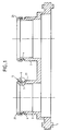
- the male element consists schematically of a flange 1 on one of the faces of which protrudes at least one projecting body 2 intended to be fitted by simple sliding in the socket which constitutes the female element 3 (figure 5).
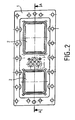
- the male element comprises two projection bodies, each being provided with an annular groove 4 intended to receive the shielding bracelet generally designated by the reference 5.
- Each projection body 2 comprises an annular chamfer 21 favoring its introduction into the female element 3 which also includes an introduction ramp 31 promoting the guidance and coupling of the two male and female elements.
- the purpose of the shielding bracelet 5 is to promote electrical continuity between the two male and female elements in order to pick up external electromagnetic interference.
- These male and female elements are obviously made of an electrically conductive material, for example a metal or a charged synthetic material and are usually connected to ground.
- the shielding bracelet consists of a plurality of contact blades 6 (FIGS. 3 and 4) held assembled and positioned in the bottom of the grooves 4 by an elastic link 7 (FIGS. 5 and 7).
- Each contact blade is made of an elastically deformable, electrically conductive material, for example made of spring metal and is shaped as an open loop, the two ends 61 and 62 of this loop being able to move freely one relative to the other. 'other. More specifically, such as visible in FIGS. 3 and 4, the contact blade comprises a main core 63, essentially rectilinear (intended to come to marry the bottom of the groove 4 of the male element), each of the ends of which is folded back to form two asymmetrical branches 64 and 65, the longest branch 64 being curved and the convexity of this branch being directed in the direction opposite to the bottom of the groove 4 serving as a seat for the contact blades.
- the contact blade comprises a main core 63, essentially rectilinear (intended to come to marry the bottom of the groove 4 of the male element), each of the ends of which is folded back to form two asymmetrical branches 64 and 65, the longest branch 64 being curved and the convexity of this branch being directed in the direction opposite to the
- the curved part of this branch 64 is extended by a rectilinear portion 66 forming an acute angle with the main core 63.
- the shortest branch 65 is, in turn, bent at 90 ° and preferably by a substantially greater angle at 90 ° and is therefore oriented in a plane substantially perpendicular to the main core 63, its end 61 being spaced from the end 62 of the branch 64.
- the central core 63 has a transverse fold 67 which for example takes the form of a triangle, the point 68 of which is directed upwards, that is to say in the direction of the convex part 69 of the loop.
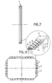
- This fold which extends over the entire width of the contact blade cooperates with a groove of complementary shape 71 formed on the internal face of the flexible bracelet 7 (FIG. 7) which, here, is of polygonal section.
- the contact blades 6 are assembled, or more precisely joined together by the elastic bracelet 7, (FIGS. 1 and 5), said bracelet being housed inside the loops constituting the contact blades so as to form a bonding agent. between the different blades.
- the bracelet 7 is preferably made of an elastically extensible material giving it a radial elasticity so that it can be engaged in the annular seat that constitutes the groove 4 by simple stretching and that it takes its place and self-positions in throat 4 by elastic return.
- the bracelet 7 is in the form of a continuous closed ring housed inside the contact blades 6, before their conformation in open loop or inserted later using the elasticity specific to the metal which allows a certain deformation without harming the conformation of the loops, the latter resuming their initial shape, after passage of the elastic strap, by simple spring effect.
- the contact blades 6 are assembled to the bracelet 7 by embedding their positioning fold 67 in the corresponding groove 71 of the connecting bracelet and are positioned and locked in the groove 4 by this bracelet, the width of the contact blades being substantially equal to that of said gorge.
- the bracelet has (see fig. 8) wider parts 71 at the corners of the case, which facilitates positioning.
- the wider parts 71 which do not carry contact blades 6, are substantially more rigid than the rest of the elastic link and are positioned at the rounded angles of the corresponding groove 4.
- the width of these wider parts 71 is for example substantially equal to the length of the contact blades 6.
- the contact blades have the shape illustrated in FIG. 3, the end 62 of the main branch 64 being located at a distance from the main core 63, pressed into the bottom of the groove 4.
- the convex part 69 of the contact blades meets the annular chamfer 31 of the female element and the branch 64 disappears gradually as the two male and female elements are introduced one into the other, the convex part of the contact blade constituting the support zone, sliding on the ramp which constitutes the introduction chamfer 31.
- FIG. 4 shows in solid lines the position of the branch 64 after deformation, that is to say after introduction of the male element into the female element while the line in dashed lines illustrates its original position before deformation as illustrated in FIG. 3. It can be seen that the end 62 of the straight portion 66 of the main branch 64 has slid in the direction of the main core 63, relative to the shorter branch 65 which has not undergone any deformation. At the end of introduction, this end 62 is moreover not in contact with the core 63, which makes it possible to avoid additional forces increasing the forces during the introduction of the housing.
- the contact blades 6 surround the major part of the body in projection of the male element, these being spaced apart and retained between them by the elastic link 7 in the form of a closed continuous ring.
- the rounded angles of this projected body are free of contact blades, but this absence does not affect the electrical continuity between the two male and female connection boxes because of the large number of contact blades on each of the four sides of the body. the male element.
- FIG. 6 shows two contact blades 6 located in the same alignment and self-positioned by their fold 67 embedded in the groove 71 of the flexible bracelet 7.
- the shape of the projected body 2 of the male element can vary and be, as illustrated in FIG. 2, square or rectangular.
- this body can be circular without detracting from the concept of the invention and in this case it will suffice to use an elastic bracelet of a shape and dimension appropriate to those of the groove carried by the element. male.
- the shielding strap according to the invention thus allows self-positioning of the contact blades on the flexible connecting strap in order to form a unitary assembly that can be easily manipulated, also coming to self-position in the corresponding groove of the connection box without making call for subsequent stapling, gluing, crimping or soldering operations.
Landscapes
- Details Of Connecting Devices For Male And Female Coupling (AREA)
- Multi-Conductor Connections (AREA)
- Shielding Devices Or Components To Electric Or Magnetic Fields (AREA)
Applications Claiming Priority (2)
| Application Number | Priority Date | Filing Date | Title |
|---|---|---|---|
| FR9114796A FR2684494B1 (fr) | 1991-11-29 | 1991-11-29 | Bracelet de blindage pour connecteurs electriques, et connecteurs equipes d'un tel bracelet. |
| FR9114796 | 1991-11-29 |
Publications (2)
| Publication Number | Publication Date |
|---|---|
| EP0545751A1 true EP0545751A1 (de) | 1993-06-09 |
| EP0545751B1 EP0545751B1 (de) | 1995-10-11 |
Family
ID=9419496
Family Applications (1)
| Application Number | Title | Priority Date | Filing Date |
|---|---|---|---|
| EP92403029A Expired - Lifetime EP0545751B1 (de) | 1991-11-29 | 1992-11-10 | Abschirmungsfederstreifen für elektrische Verbinder und damit ausgestatteter Verbinder |
Country Status (7)
| Country | Link |
|---|---|
| US (1) | US5445542A (de) |
| EP (1) | EP0545751B1 (de) |
| AT (1) | ATE129100T1 (de) |
| CA (1) | CA2083973A1 (de) |
| DE (1) | DE69205401T2 (de) |
| ES (1) | ES2079160T3 (de) |
| FR (1) | FR2684494B1 (de) |
Cited By (1)
| Publication number | Priority date | Publication date | Assignee | Title |
|---|---|---|---|---|
| WO1997045898A1 (en) * | 1996-05-31 | 1997-12-04 | The Whitaker Corporation | Shield member for panel mount connector |
Families Citing this family (8)
| Publication number | Priority date | Publication date | Assignee | Title |
|---|---|---|---|---|
| US5647765A (en) * | 1995-09-12 | 1997-07-15 | Regal Electronics, Inc. | Shielded connector with conductive gasket interface |
| DE29701838U1 (de) * | 1997-02-03 | 1998-08-27 | Siemens AG, 80333 München | Elektrisches Gerät mit einer Schirmanbindung |
| EP2115820B1 (de) * | 2007-01-31 | 2015-09-30 | Multi-Holding AG | Kontaktelement sowie anwendung eines solchen kontaktelements in einer steckverbindung |
| US7704097B1 (en) * | 2009-02-17 | 2010-04-27 | Tyco Electronics Corporation | Connector assembly having an electromagnetic seal element |
| KR101779454B1 (ko) * | 2017-03-15 | 2017-09-18 | 주식회사 기가레인 | 연결 커넥터 및 이를 이용한 블라인드 메이팅 커넥터 |
| US20200274300A1 (en) * | 2019-02-27 | 2020-08-27 | Te Connectivity Corporation | High speed connector with moldable conductors |
| CN110581419A (zh) * | 2019-09-24 | 2019-12-17 | 成都凯迪飞研科技有限责任公司 | 航空电缆连接器后附件高可靠紧固装置 |
| RU2754091C1 (ru) * | 2020-12-02 | 2021-08-26 | Федеральное государственное казенное военное образовательное учреждение высшего образования "Военный учебно-научный центр Военно-Морского Флота "Военно-морская академия им. Адмирала Флота Советского Союза Н.Г. Кузнецова" | Способ увеличения контактного нажатия и площади контактирующей поверхности контактных элементов разъемного электрического соединения пропорционально проходящему по нему току |
Citations (4)
| Publication number | Priority date | Publication date | Assignee | Title |
|---|---|---|---|---|
| FR2360191A1 (fr) * | 1976-07-26 | 1978-02-24 | Automation Ind Inc | Dispositif de protection d'un connecteur electrique contre les frequences parasites et procede de fabrication de ce dispositif |
| EP0310945A2 (de) * | 1987-10-05 | 1989-04-12 | Itt Industries, Inc. | Abschirmung für elektrischen Verbinder |
| US4874337A (en) * | 1988-11-23 | 1989-10-17 | Amp Incorporated | Method of mounting a replaceable EMI spring strip |
| EP0358562A1 (de) * | 1988-09-05 | 1990-03-14 | RADIALL Société anonyme dite: | Abgeschirmtes Verbindungsgehäuse |
Family Cites Families (6)
| Publication number | Priority date | Publication date | Assignee | Title |
|---|---|---|---|---|
| US3609632A (en) * | 1968-08-19 | 1971-09-28 | Trw Inc | Releasable electrical connector |
| US3597724A (en) * | 1968-09-23 | 1971-08-03 | G & H Technology | Connector |
| US3678445A (en) * | 1970-07-31 | 1972-07-18 | Itt | Electrical connector shield |
| US4432919A (en) * | 1982-03-29 | 1984-02-21 | Rinehart John R | Method of making a composite foam taxidermy mannikin |
| US4529257A (en) * | 1983-02-22 | 1985-07-16 | International-Telephone & Telegraph Corp. | Combined electrical shield and environmental seal for electrical connector |
| US4655532A (en) * | 1986-02-06 | 1987-04-07 | Allied Corporation | Circumferential grounding and shielding ring for an electrical connector |
-
1991
- 1991-11-29 FR FR9114796A patent/FR2684494B1/fr not_active Expired - Lifetime
-
1992
- 1992-11-10 EP EP92403029A patent/EP0545751B1/de not_active Expired - Lifetime
- 1992-11-10 ES ES92403029T patent/ES2079160T3/es not_active Expired - Lifetime
- 1992-11-10 AT AT92403029T patent/ATE129100T1/de not_active IP Right Cessation
- 1992-11-10 DE DE69205401T patent/DE69205401T2/de not_active Expired - Fee Related
- 1992-11-27 CA CA002083973A patent/CA2083973A1/en not_active Abandoned
-
1994
- 1994-05-19 US US08/245,825 patent/US5445542A/en not_active Expired - Lifetime
Patent Citations (4)
| Publication number | Priority date | Publication date | Assignee | Title |
|---|---|---|---|---|
| FR2360191A1 (fr) * | 1976-07-26 | 1978-02-24 | Automation Ind Inc | Dispositif de protection d'un connecteur electrique contre les frequences parasites et procede de fabrication de ce dispositif |
| EP0310945A2 (de) * | 1987-10-05 | 1989-04-12 | Itt Industries, Inc. | Abschirmung für elektrischen Verbinder |
| EP0358562A1 (de) * | 1988-09-05 | 1990-03-14 | RADIALL Société anonyme dite: | Abgeschirmtes Verbindungsgehäuse |
| US4874337A (en) * | 1988-11-23 | 1989-10-17 | Amp Incorporated | Method of mounting a replaceable EMI spring strip |
Non-Patent Citations (1)
| Title |
|---|
| ELECTRONIC DESIGN. vol. 2, no. 3200, Septembre 1975, HASBROUCK HEIGHTS, NEW JERSEY pages 393 - 399 'finger strips and rings micro - processed from beryllium copper for rfi - emi shielding' * |
Cited By (2)
| Publication number | Priority date | Publication date | Assignee | Title |
|---|---|---|---|---|
| WO1997045898A1 (en) * | 1996-05-31 | 1997-12-04 | The Whitaker Corporation | Shield member for panel mount connector |
| US5766041A (en) * | 1996-05-31 | 1998-06-16 | The Whitaker Corporation | Shield member for panel mount connector |
Also Published As
| Publication number | Publication date |
|---|---|
| DE69205401T2 (de) | 1996-03-21 |
| FR2684494A1 (fr) | 1993-06-04 |
| EP0545751B1 (de) | 1995-10-11 |
| ES2079160T3 (es) | 1996-01-01 |
| FR2684494B1 (fr) | 1995-07-07 |
| DE69205401D1 (de) | 1995-11-16 |
| US5445542A (en) | 1995-08-29 |
| CA2083973A1 (en) | 1993-05-30 |
| ATE129100T1 (de) | 1995-10-15 |
Similar Documents
| Publication | Publication Date | Title |
|---|---|---|
| EP0519812B1 (de) | Koaxialverbinder zum Verbinden eines Koaxialkabels mit einer elektronischen gedruckten Schaltung | |
| EP0491626B1 (de) | Elektrischer Koaxialverbinder | |
| EP0545751B1 (de) | Abschirmungsfederstreifen für elektrische Verbinder und damit ausgestatteter Verbinder | |
| FR2475812A1 (fr) | Organe de connexion electrique comportant un mecanisme perfectionne s'opposant au desassemblage | |
| FR2559624A1 (fr) | Organe de contact electrique | |
| FR2582453A1 (fr) | Joint pour la realisation d'un connecteur electrique etanche et connecteur realise avec un tel joint | |
| FR2789811A1 (fr) | Raccord coaxial pour relier deux cartes de circuit imprime | |
| FR2717623A1 (fr) | Connecteur pour câble coaxial. | |
| EP0303529B1 (de) | Aufnahmebuchse für einen Stecker zur Auführung einer elektrischen Verbindung und elektrischer Steckverbinder, der mindestens eine solche Buchse aufweist | |
| FR2494510A1 (fr) | Element de connecteur electrique | |
| EP0580469B1 (de) | Steckverbindersatz und Befestigungsfläche insbesondere für die Avionik | |
| EP0666618B1 (de) | Elektrischer Koaxialverbinder mit Schaltfunktion | |
| EP0186804B1 (de) | Am Armgelenk zu tragende elektronische Vorrichtung | |
| FR2508722A1 (fr) | Ensemble de pieces interieures rapportees de connecteur electrique | |
| FR2696840A1 (fr) | Fiche encliquetable de connexion de fibre optique, notamment fiche monobloc surmoulée. | |
| FR2518829A1 (fr) | Contact a broche electrique active | |
| EP1670301B1 (de) | Verbindungsanordnung bestehend aus einem Halter mit einer Öffnung und einem Verbindergehäuse montiert auf dem Halter | |
| FR2467492A1 (fr) | Connecteur electrique a joint d'hermeticite peripherique | |
| FR2510823A1 (fr) | Connecteur electrique decrochable | |
| FR3034263B1 (fr) | "connecteur electrique miniature unitaire a elements de contact extractibles, et outil associe de deverrouillage et d'extraction des elements de contact" | |
| FR2563383A1 (fr) | Fiche de prise de courant a element de traction | |
| CA3195074A1 (fr) | Connecteur pour la connexion d'une terminaison electrique sur un circuit imprime, procedes d'assemblage correspondants | |
| FR2565423A1 (fr) | Borne a receptacle a pattes | |
| FR2498272A1 (fr) | Collier de raccordement pour dispositif de fixation a baionnette | |
| FR2685429A1 (fr) | Electrovanne a noyau mobile plat. |
Legal Events
| Date | Code | Title | Description |
|---|---|---|---|
| PUAI | Public reference made under article 153(3) epc to a published international application that has entered the european phase |
Free format text: ORIGINAL CODE: 0009012 |
|
| AK | Designated contracting states |
Kind code of ref document: A1 Designated state(s): AT BE DE ES GB IT NL |
|
| 17P | Request for examination filed |
Effective date: 19930713 |
|
| 17Q | First examination report despatched |
Effective date: 19940422 |
|
| RAP1 | Party data changed (applicant data changed or rights of an application transferred) |
Owner name: FRAMATOME CONNECTORS FRANCE |
|
| GRAA | (expected) grant |
Free format text: ORIGINAL CODE: 0009210 |
|
| AK | Designated contracting states |
Kind code of ref document: B1 Designated state(s): AT BE DE ES GB IT NL |
|
| PG25 | Lapsed in a contracting state [announced via postgrant information from national office to epo] |
Ref country code: AT Effective date: 19951011 |
|
| REF | Corresponds to: |
Ref document number: 129100 Country of ref document: AT Date of ref document: 19951015 Kind code of ref document: T |
|
| GBT | Gb: translation of ep patent filed (gb section 77(6)(a)/1977) |
Effective date: 19951010 |
|
| REF | Corresponds to: |
Ref document number: 69205401 Country of ref document: DE Date of ref document: 19951116 |
|
| ITF | It: translation for a ep patent filed | ||
| REG | Reference to a national code |
Ref country code: ES Ref legal event code: FG2A Ref document number: 2079160 Country of ref document: ES Kind code of ref document: T3 |
|
| PLBE | No opposition filed within time limit |
Free format text: ORIGINAL CODE: 0009261 |
|
| STAA | Information on the status of an ep patent application or granted ep patent |
Free format text: STATUS: NO OPPOSITION FILED WITHIN TIME LIMIT |
|
| 26N | No opposition filed | ||
| REG | Reference to a national code |
Ref country code: GB Ref legal event code: IF02 |
|
| PGFP | Annual fee paid to national office [announced via postgrant information from national office to epo] |
Ref country code: ES Payment date: 20020926 Year of fee payment: 11 |
|
| PGFP | Annual fee paid to national office [announced via postgrant information from national office to epo] |
Ref country code: GB Payment date: 20021106 Year of fee payment: 11 |
|
| PGFP | Annual fee paid to national office [announced via postgrant information from national office to epo] |
Ref country code: BE Payment date: 20021120 Year of fee payment: 11 |
|
| PGFP | Annual fee paid to national office [announced via postgrant information from national office to epo] |
Ref country code: DE Payment date: 20030130 Year of fee payment: 11 |
|
| NLT1 | Nl: modifications of names registered in virtue of documents presented to the patent office pursuant to art. 16 a, paragraph 1 |
Owner name: FCI FRANCE |
|
| REG | Reference to a national code |
Ref country code: ES Ref legal event code: PC2A |
|
| PG25 | Lapsed in a contracting state [announced via postgrant information from national office to epo] |
Ref country code: GB Free format text: LAPSE BECAUSE OF NON-PAYMENT OF DUE FEES Effective date: 20031110 |
|
| PG25 | Lapsed in a contracting state [announced via postgrant information from national office to epo] |
Ref country code: ES Free format text: LAPSE BECAUSE OF NON-PAYMENT OF DUE FEES Effective date: 20031111 |
|
| PG25 | Lapsed in a contracting state [announced via postgrant information from national office to epo] |
Ref country code: BE Free format text: LAPSE BECAUSE OF NON-PAYMENT OF DUE FEES Effective date: 20031130 |
|
| BERE | Be: lapsed |
Owner name: *FCI FRANCE Effective date: 20031130 |
|
| PG25 | Lapsed in a contracting state [announced via postgrant information from national office to epo] |
Ref country code: DE Free format text: LAPSE BECAUSE OF NON-PAYMENT OF DUE FEES Effective date: 20040602 |
|
| GBPC | Gb: european patent ceased through non-payment of renewal fee |
Effective date: 20031110 |
|
| REG | Reference to a national code |
Ref country code: ES Ref legal event code: FD2A Effective date: 20031111 |
|
| PG25 | Lapsed in a contracting state [announced via postgrant information from national office to epo] |
Ref country code: IT Free format text: LAPSE BECAUSE OF NON-PAYMENT OF DUE FEES;WARNING: LAPSES OF ITALIAN PATENTS WITH EFFECTIVE DATE BEFORE 2007 MAY HAVE OCCURRED AT ANY TIME BEFORE 2007. THE CORRECT EFFECTIVE DATE MAY BE DIFFERENT FROM THE ONE RECORDED. Effective date: 20051110 |
|
| PGFP | Annual fee paid to national office [announced via postgrant information from national office to epo] |
Ref country code: NL Payment date: 20111202 Year of fee payment: 20 |
|
| REG | Reference to a national code |
Ref country code: NL Ref legal event code: V4 Effective date: 20121110 |