EP0545826B1 - Alésoir conique - Google Patents
Alésoir conique Download PDFInfo
- Publication number
- EP0545826B1 EP0545826B1 EP19920403277 EP92403277A EP0545826B1 EP 0545826 B1 EP0545826 B1 EP 0545826B1 EP 19920403277 EP19920403277 EP 19920403277 EP 92403277 A EP92403277 A EP 92403277A EP 0545826 B1 EP0545826 B1 EP 0545826B1
- Authority
- EP
- European Patent Office
- Prior art keywords
- reamer
- flutes
- cutting
- tool
- followed
- Prior art date
- Legal status (The legal status is an assumption and is not a legal conclusion. Google has not performed a legal analysis and makes no representation as to the accuracy of the status listed.)
- Revoked
Links
- 229910052751 metal Inorganic materials 0.000 claims description 4
- 239000002184 metal Substances 0.000 claims description 4
- 238000005461 lubrication Methods 0.000 claims description 2
- 230000002093 peripheral effect Effects 0.000 claims description 2
- 239000000463 material Substances 0.000 description 3
- 238000003801 milling Methods 0.000 description 3
- 239000000565 sealant Substances 0.000 description 3
- 239000002131 composite material Substances 0.000 description 2
- 238000010276 construction Methods 0.000 description 2
- 239000000314 lubricant Substances 0.000 description 2
- 238000003754 machining Methods 0.000 description 2
- 229910000997 High-speed steel Inorganic materials 0.000 description 1
- 229910000831 Steel Inorganic materials 0.000 description 1
- RTAQQCXQSZGOHL-UHFFFAOYSA-N Titanium Chemical compound [Ti] RTAQQCXQSZGOHL-UHFFFAOYSA-N 0.000 description 1
- 229910052782 aluminium Inorganic materials 0.000 description 1
- XAGFODPZIPBFFR-UHFFFAOYSA-N aluminium Chemical compound [Al] XAGFODPZIPBFFR-UHFFFAOYSA-N 0.000 description 1
- 239000002173 cutting fluid Substances 0.000 description 1
- 239000000835 fiber Substances 0.000 description 1
- 239000012783 reinforcing fiber Substances 0.000 description 1
- 239000003566 sealing material Substances 0.000 description 1
- 239000010959 steel Substances 0.000 description 1
- 239000010936 titanium Substances 0.000 description 1
- 229910052719 titanium Inorganic materials 0.000 description 1
Images
Classifications
-
- B—PERFORMING OPERATIONS; TRANSPORTING
- B23—MACHINE TOOLS; METAL-WORKING NOT OTHERWISE PROVIDED FOR
- B23D—PLANING; SLOTTING; SHEARING; BROACHING; SAWING; FILING; SCRAPING; LIKE OPERATIONS FOR WORKING METAL BY REMOVING MATERIAL, NOT OTHERWISE PROVIDED FOR
- B23D77/00—Reaming tools
- B23D77/006—Reaming tools with means for lubricating or cooling
-
- B—PERFORMING OPERATIONS; TRANSPORTING
- B23—MACHINE TOOLS; METAL-WORKING NOT OTHERWISE PROVIDED FOR
- B23D—PLANING; SLOTTING; SHEARING; BROACHING; SAWING; FILING; SCRAPING; LIKE OPERATIONS FOR WORKING METAL BY REMOVING MATERIAL, NOT OTHERWISE PROVIDED FOR
- B23D77/00—Reaming tools
- B23D77/12—Reamers with cutting edges arranged in tapered form
Definitions
- the subject of the present invention is a reamer, in particular a conical reamer intended in particular, but not exclusively, for aeronautical construction.
- slender bodies terminated by a shank for mounting or attaching the tool to a mandrel or to any other drive device, such as a spindle holder, for example.
- a spindle holder At the periphery of the body extend straight or more generally helical cutting edges usually three in number. These edges extend radially towards the rear by a draft followed by an undercut.
- the edges and the flutes which connect them are of the same pitch and of the same direction. This means that the tools being driven, viewed from above, clockwise, the edges and flutes are on the right.
- the purpose of flutes is in particular to evacuate the chips towards the top or rear of the tool.
- FR-A-2 516 830 relates to a cylindrical reamer, the front part of which is conical, making it possible to make cylindrical holes in composite materials including high strength fibers.
- the teeth propeller preferably has a step to the left while the teeth are cut to cut to the right.
- a smooth head for centering the tool At the front of the tool is provided a smooth head for centering the tool. This tool is particularly suitable for materials comprising reinforcing fibers.
- Conical rivets are used, in aircraft construction, to assemble several superimposed sheets in order to constitute structures such as airplane wings or fuselage parts.
- a layer of polymerizable sealing material such as that which is designated in the art by "PR”.
- PR polymerizable sealing material
- a first object of the invention is to propose a tool which overcomes this drawback.
- a second object of the invention is to enable a satisfactory surface condition to be obtained in a single pass in a metal (aluminum, titanium, steel, etc.) with a single tool.
- the reamer for boring a hole in metal comprising at least three composite helical peripheral edges separated by flutes, an attachment head and tail, the propeller being in one direction and cutting in the 'other direction the front part of the reamer having a cylindrical casing
- the cylindrical casing of the front part of the reamer has a reduced section compared to the minimum section of the casing of the conical body for forming a cutting pilot stage, the body continuing with a milling cone, a corresponding central lubrication duct with radial holes, alternating along the length of the body of the reamer.
- the pilot allows good alignment to be found by re-machining the holes.
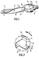
- the tool consists of a front part 1 extended by the conical body 2 itself which continues with a head 3 from which protrudes an attachment tail 4 which, in the The example shown is threaded.
- the front part 1 intended to form a pilot stage for the tool also consists of helical edges separated by flutes but it is inscribed in a cylindrical envelope (not shown) whose diameter is less than the minimum diameter of the envelope of body 2 of the reamer.
- the elongate body 2 has cutting helical edges 5, three in number in the example shown, projecting from the flutes 6 which are also helical on the left. Thus, the chips and the sealant are removed to the bottom of the tool.
- the cutting angle of the edges is 4 ° and each edge 5 comprises a fine strip 10, for example from 0.1 to 0.2 mm. width which improves the finish quality of the bore and reduces the cutting forces and the machining time.
- the listel 10 is followed by a draft 11 from 6 to 8 ° itself followed by an undercut 12 from 25 to 30 °, for example.
- the flutes 6 are preferably polished, which ensures good sliding of the chips and contributes to the quality of the result obtained.
- holes 7 corresponding with an axial channel (not shown) for supplying lubricant and distributing it over the entire height of the reamer.
- the axial channel is itself connected to a source of lubricant distribution.
- the radial holes 7 are formed in alternating positions to ensure a homogeneous distribution of the cutting fluid.
- the body 2 is extended by a milling cone 9 at 100 °, for example, itself connected to the head 3.
- longitudinal notches 8 facilitate assembly and disassembly by the front face.
- the tool according to the invention is made of high-speed steel for example. It allows you to perform several operations, alignment, reaming, milling, and ... in a single pass.
Landscapes
- Engineering & Computer Science (AREA)
- Mechanical Engineering (AREA)
- Milling, Broaching, Filing, Reaming, And Others (AREA)
Description
- La présente invention a pour objet un alésoir, en particulier un alésoir conique destiné en particulier, mais non exclusivement, à la construction aéronautique.
- De tels outils sont bien connus et servent à préparer des trous coniques destinés à recevoir des rivets ou autres moyens de fixation analogues, également coniques, tels que ceux qui sont désignés dans la technique sous l'appellation de "TAPER LOK".
- Ils comprennent d'une manière générale un corps longiligne terminé par une queue pour le montage ou attachement de l'outil sur un mandrin ou sur tout autre dispositif d'entraînement, tel qu'un fourreau porte-broche, par exemple. A la périphérie du corps s'étendent des arêtes coupantes rectilignes ou plus généralement hélicoïdales habituellement au nombre de trois. Ces arêtes se prolongent radialement vers l'arrière par une dépouille suivie d'une contre-dépouille. Les arêtes et les goujures qui les relient sont de même pas et de même sens. C'est à dire que les outils étant entraînés, en vue par dessus, dans le sens horaire, les arêtes et les goujures sont à droite. Les goujures ont notamment pour but d'évacuer les copeaux vers le haut ou arrière de l'outil.
- FR-A-2 516 830 concerne un alésoir cylindrique, dont la partie avant est conique, permettant de réaliser des trous cylindriques dans des matériaux composites incluant des fibres à haute résistance. Pour éviter que l'outil ne se visse dans le matériau, l'hélice de la denture a de préférence un pas à gauche alors que les dents sont taillées pour couper à droite. A l'avant de l'outil est prévue une tête lisse pour le centrage de l'outil. Cet outil est particulièrement adapté pour des matériaux comprenant des fibres de renforcement.
- Les rivets coniques sont utilisés, dans la construction aéronautique, pour assembler plusieurs feuilles superposées en vue de constituer des structures telles que les ailes d'avion ou des parties de fuselage. Mais, en raison des conditions d'utilisation, il est nécessaire de disposer entre deux feuilles métalliques à assembler une couche de matériau d'étanchéité polymérisable tel que celui qui est désigné dans la technique par "PR". Lorsque l'alésage est réalisé, le produit n'est pas encore dur. Il s'est avéré que ce matériau provoquait des bourrages à l'intérieur des goujures, de sorte que les copeaux portaient contre la surface de l'alésage ce qui en altérait l'état.
- Un premier objet de l'invention est de proposer un outil palliant cet inconvénient.
- D'autre part, lorsque l'on assemble des feuilles superposées, les trous de passage des rivets sont rarement exactement en face l'un de l'autre. Il est donc nécessaire d'effectuer une première passe de l'outil qui effectue un dégrossissage puis une seconde passe de finition, quelquefois avec des outils différents.
- Un second objet de l'invention est de permettre l'obtention d'un état de surface satisfaisant en une seule passe dans un métal (aluminium, titane, acier etc...) avec un outil unique.
- Selon la présente invention, l'alésoir destiné à aléser un trou dans du métal comprenant au moins trois arêtes composites périphériques hélicoïdales séparées par des goujures, une tête et une queue d'attachement, l'hélice étant dans un sens et la coupe dans l'autre sens la partie avant de l'alésoir présentant une enveloppe cylindrique, est caractérisé en ce que l'enveloppe cylindrique de la partie avant de l'alésoir présente une section réduite par rapport à la section minimale de l'enveloppe du corps conique pour former un étage pilote coupant, le corps se poursuivant par un cône de fraisage, un conduit central de lubrification correspondant avec des trous radiaux, alterné sur la longueur du corps de l'alésoir.
- Lorsque les arêtes sont à coupe à droite, les hélices sont à gauche. Pour un outil tournant en sens contraire , dans le sens antihoraire en vue par-dessus, l'hélice serait à droite avec la coupe à gauche. Cela se traduit par le fait que les copeaux au lieu d'être évacués vers le haut ou arrière de l'outil sont évacués vers le bas ou avant et ils s'échappent par les trous préalablement percés dans les tôles. Il a été constaté que, dans ces conditions, l'inconvénient de bourrage dû au produit d'étanchéité était éliminé .
- Lorsque les trous prépercés dans les tôles à assembler ne sont pas correctement alignés, le pilote permet de retrouver un bon alignement en réusinant les perçages.
- D'autres caractéristiques et avantages de l'invention apparaîtront au cours de la description qui va suivre d'un mode particulier de réalisation, donné uniquement à titre d'exemple non limitatif, en regard des dessins qui représentent :
- La figure 1, en perspective un alésoir selon l'invention;
- la figure 2, une vue en bout, par l'avant du même alésoir.
- Sur la figure 1, on voit que l'outil se compose d'une partie avant 1 prolongée par le corps conique 2 proprement dit qui se poursuit par une tête 3 à partir de laquelle fait saillie une queue d'attachement 4 qui, dans l'exemple représenté, est filetée. La partie avant 1, destinée à former un étage pilote pour l'outil est également constituée d'arêtes hélicoïdales séparées par des goujures mais elle s'inscrit dans une enveloppe cylindrique (non représentée) dont le diamètre est inférieur au diamètre minimal de l'enveloppe du corps 2 de l'alésoir. Le corps 2 longiligne comporte des arêtes hélicoïdales coupantes 5, au nombre de trois dans l'exemple représenté, en saillie par rapport aux goujures 6 qui sont également hélicoïdales à gauche. Ainsi, les copeaux et le produit d'étanchéité sont évacués vers le bas de l'outil.
- Comme cela apparaît sur la figure 2, l'angle de coupe des arêtes est de 4° et chaque arête 5 comprend un listel fin 10, par exemple de 0,1 à 0,2 mm. de largeur ce qui améliore la qualité de finition de l'alésage et diminue les efforts de coupe et le temps d'usinage. Le listel 10 est suivi d'une dépouille 11 de 6 à 8° elle-même suivie d'une contre-dépouille 12 de 25 à 30°, par exemple. Afin de permettre un meilleur dégagement des copeaux et du produit d'étanchéité, les goujure 6 sont, de préférence, polies ce qui assure un bon glissement des copeaux et contribue à la qualité du résultat obtenu.
- Dans le pilote 1 et dans le corps 2 apparaissent des trous 7, correspondant avec un canal axial (non représenté) permettant d'amener du lubrifiant et de distribuer celui-ci sur toute la hauteur de l'alésoir. Le canal axial est lui-même relié à une source de distribution de lubrifiant. Les trous radiaux 7 sont formés en des positions alternées pour assurer une distribution homogène du fluide de coupe.
- Dans l'exemple représenté, le corps 2 se prolonge par un cône de fraisage 9 à 100°, par exemple, lui-même relié à la tête 3. Dans le cas d'une queue filetée destinée à être montée dans un porte broche, des encoches longitudinales 8 facilitent le montage et le démontage par la face avant.
- L'outil selon l'invention est réalisé en acier rapide par exemple. Il permet d'effectuer plusieurs opérations, alignement, alésage, fraisurage, et...en une seule passe.
Claims (4)
- Alésoir destiné à aléser un trou dans du métal comprenant au moins trois arêtes coupantes périphériques hélicoïdales (5) séparées par des goujures (6), une tête (3) et une queue d'attachement (4), l'hélice étant dans un sens et la coupe dans l'autre sens, la partie avant (1) de l'alésoir présentant une enveloppe cylindrique caractérisé, en ce que l'enveloppe cylindrique présente une section réduite par rapport à la section minimale de l'enveloppe du corps conique (2) pour former un étage pilote coupant, le corps (2) se poursuivant par un cône de fraisage (9), un conduit central de lubrification correspondant avec des trous radiaux (7), alterné sur la longueur du corps de l'alésoir.
- Alésoir selon la revendication 3, caractérisé en ce que la queue (4) étant filetée, des encoches (8) longitudinales sont formées dans la partie avant du cône (9).
- Alésoir selon l'une quelconque des revendications précédentes, caractérisé en ce que les goujures (6) sont polies.
- Alésoir selon l'une quelconque des revendications précédentes, caractérisé en ce que les arêtes coupantes (5) présentant un listel fin (10) suivi d'un angle de dépouille de 6 à 8° et d'un angle de contre-dépouille de 25 à 30°.
Applications Claiming Priority (2)
| Application Number | Priority Date | Filing Date | Title |
|---|---|---|---|
| FR9115070 | 1991-12-05 | ||
| FR9115070A FR2684583B1 (fr) | 1991-12-05 | 1991-12-05 | Alesoir conique. |
Publications (2)
| Publication Number | Publication Date |
|---|---|
| EP0545826A1 EP0545826A1 (fr) | 1993-06-09 |
| EP0545826B1 true EP0545826B1 (fr) | 1997-03-19 |
Family
ID=9419699
Family Applications (1)
| Application Number | Title | Priority Date | Filing Date |
|---|---|---|---|
| EP19920403277 Revoked EP0545826B1 (fr) | 1991-12-05 | 1992-12-04 | Alésoir conique |
Country Status (3)
| Country | Link |
|---|---|
| EP (1) | EP0545826B1 (fr) |
| DE (2) | DE69218350T2 (fr) |
| FR (1) | FR2684583B1 (fr) |
Cited By (1)
| Publication number | Priority date | Publication date | Assignee | Title |
|---|---|---|---|---|
| DE19728384B8 (de) * | 1997-07-03 | 2010-03-04 | August Beck Gmbh & Co | Rotierendes Schaftwerkzeug |
Families Citing this family (7)
| Publication number | Priority date | Publication date | Assignee | Title |
|---|---|---|---|---|
| ES2158329T3 (es) * | 1995-07-14 | 2001-09-01 | Kennametal Inc | Broca con canal de lubricante-refrigerante. |
| DE19730377C2 (de) * | 1997-07-16 | 2002-10-10 | Airbus Gmbh | Reibahle zur Herstellung von zylindrischen Paßbohrungen in Werkstücken aus Aluminium-Legierungen |
| EP1561535B1 (fr) * | 2004-02-06 | 2012-01-04 | Volvo Car Corporation | Outil de coupe et procédé pour l'utilisation dudit outil |
| FR2983422B1 (fr) * | 2011-12-01 | 2014-08-01 | Airbus Operations Sas | Meche pour outil alesant conique |
| US10065250B2 (en) * | 2014-02-10 | 2018-09-04 | Kuritakoki Co., Ltd. | Drill and method of drilling a hole |
| DE102014108219B4 (de) | 2014-06-12 | 2020-12-17 | Kennametal Inc. | Rotationswerkzeug sowie Verfahren zur Herstellung eines Rotationswerkzeugs |
| US10562109B2 (en) * | 2017-11-22 | 2020-02-18 | The Boeing Company | Tapered drill bit and automated process |
Family Cites Families (5)
| Publication number | Priority date | Publication date | Assignee | Title |
|---|---|---|---|---|
| DE546245C (de) * | 1932-03-12 | Josef Baakes | Kegelreibahle mit zwei oder mehreren stark schraubenlinienfoermig gewundenen, im gleichen Richtungssinne verlaufenden Schneidzaehnen | |
| FR702342A (fr) * | 1930-09-18 | 1931-04-04 | Perfectionnements aux outils d'alésage, de fraisage, etc., à rainures hélicoïdales | |
| FR1287928A (fr) * | 1961-04-28 | 1962-03-16 | Cold Point Ltd | Alésoir |
| FR2516830A1 (fr) * | 1981-11-20 | 1983-05-27 | Dassault Avions | Alesoir convenant en particulier au percage des materiaux composites |
| FR2590191B1 (fr) * | 1985-11-18 | 1989-09-15 | Recoules Et Fils Sa | Outil de coupe monobloc a plusieurs etages pour le prealesage et l'alesage |
-
1991
- 1991-12-05 FR FR9115070A patent/FR2684583B1/fr not_active Expired - Fee Related
-
1992
- 1992-12-04 DE DE1992618350 patent/DE69218350T2/de not_active Revoked
- 1992-12-04 DE DE1992403277 patent/DE545826T1/de active Pending
- 1992-12-04 EP EP19920403277 patent/EP0545826B1/fr not_active Revoked
Cited By (2)
| Publication number | Priority date | Publication date | Assignee | Title |
|---|---|---|---|---|
| DE19728384B8 (de) * | 1997-07-03 | 2010-03-04 | August Beck Gmbh & Co | Rotierendes Schaftwerkzeug |
| DE19728384C5 (de) * | 1997-07-03 | 2010-04-15 | August Beck Gmbh & Co | Rotierendes Schaftwerkzeug |
Also Published As
| Publication number | Publication date |
|---|---|
| DE69218350D1 (de) | 1997-04-24 |
| FR2684583B1 (fr) | 1995-12-01 |
| DE69218350T2 (de) | 1997-08-21 |
| EP0545826A1 (fr) | 1993-06-09 |
| DE545826T1 (de) | 1994-06-16 |
| FR2684583A1 (fr) | 1993-06-11 |
Similar Documents
| Publication | Publication Date | Title |
|---|---|---|
| EP0298285B1 (fr) | Fraise à plaquettes de coupe amovibles | |
| JP5101515B2 (ja) | 回転式切削工具 | |
| EP1126943B1 (fr) | Instrument de coupe pour usiner des alesages dans des materiaux a rappel elastique | |
| EP2018918B1 (fr) | Foret pour perçage grande vitesse de matériaux composites | |
| US6354773B1 (en) | Wood boring drill bit | |
| US4740121A (en) | Reamer with unequally spaced flutes | |
| US4662803A (en) | Reamer with unequally spaced flutes | |
| US5071294A (en) | Burnishing drill | |
| JPH0790409B2 (ja) | さら穴等工作回転カッタ | |
| EP2167263B1 (fr) | Outil pour usinage par enlèvement de copeaux ainsi qu'un corps de base associé | |
| EP0482982A1 (fr) | Dispositif de perçage à évacuation de copeaux perfectionnée | |
| CN100503105C (zh) | 深孔钻头及其组装方法以及可更换切削头 | |
| EP2030712A1 (fr) | Fraise à rainurer pour usinage à grande avance et à faible profondeur de passe | |
| EP2457678B1 (fr) | Outil de coupe monobloc bimatériaux | |
| WO2008014367A1 (fr) | Outil de coupe à pointe remplaçable | |
| FR2861001A1 (fr) | Foret ceramique pour percage grande vitesse | |
| EP0545826A1 (fr) | Alésoir conique | |
| US4449865A (en) | Method and tool for generating countersunk holes in composite materials | |
| WO2020221603A1 (fr) | Outil de coupe à lubrification intégrée | |
| US4134704A (en) | Tapered hole cutter | |
| EP0195838B1 (fr) | Alésoir à dents inégalement espacées | |
| FR2827204A1 (fr) | Outil de coupe rotatif et procede d'usinage grande vitesse avec nano lubrification, utilisant un tel outil | |
| FR2590191A1 (fr) | Outil de coupe monobloc a plusieurs etages pour le prealesage et l'alesage | |
| FR2516830A1 (fr) | Alesoir convenant en particulier au percage des materiaux composites | |
| CA3135507A1 (fr) | Outil rotatif de coupe, tel qu'un foret ou un alesoir |
Legal Events
| Date | Code | Title | Description |
|---|---|---|---|
| PUAI | Public reference made under article 153(3) epc to a published international application that has entered the european phase |
Free format text: ORIGINAL CODE: 0009012 |
|
| AK | Designated contracting states |
Kind code of ref document: A1 Designated state(s): DE FR GB |
|
| 17P | Request for examination filed |
Effective date: 19931203 |
|
| DET | De: translation of patent claims | ||
| RAP1 | Party data changed (applicant data changed or rights of an application transferred) |
Owner name: AEROSPATIALE SOCIETE NATIONALE INDUSTRIELLE Owner name: ETABLISSEMENTS RECOULES ET FILS (S.A) |
|
| 17Q | First examination report despatched |
Effective date: 19950913 |
|
| GRAG | Despatch of communication of intention to grant |
Free format text: ORIGINAL CODE: EPIDOS AGRA |
|
| GRAH | Despatch of communication of intention to grant a patent |
Free format text: ORIGINAL CODE: EPIDOS IGRA |
|
| GRAH | Despatch of communication of intention to grant a patent |
Free format text: ORIGINAL CODE: EPIDOS IGRA |
|
| GRAA | (expected) grant |
Free format text: ORIGINAL CODE: 0009210 |
|
| AK | Designated contracting states |
Kind code of ref document: B1 Designated state(s): DE FR GB |
|
| REF | Corresponds to: |
Ref document number: 69218350 Country of ref document: DE Date of ref document: 19970424 |
|
| GBT | Gb: translation of ep patent filed (gb section 77(6)(a)/1977) |
Effective date: 19970416 |
|
| PLBQ | Unpublished change to opponent data |
Free format text: ORIGINAL CODE: EPIDOS OPPO |
|
| PLBI | Opposition filed |
Free format text: ORIGINAL CODE: 0009260 |
|
| PLBF | Reply of patent proprietor to notice(s) of opposition |
Free format text: ORIGINAL CODE: EPIDOS OBSO |
|
| 26 | Opposition filed |
Opponent name: GUEHRING OHG Effective date: 19971219 |
|
| PLBF | Reply of patent proprietor to notice(s) of opposition |
Free format text: ORIGINAL CODE: EPIDOS OBSO |
|
| PLBF | Reply of patent proprietor to notice(s) of opposition |
Free format text: ORIGINAL CODE: EPIDOS OBSO |
|
| PLBF | Reply of patent proprietor to notice(s) of opposition |
Free format text: ORIGINAL CODE: EPIDOS OBSO |
|
| PGFP | Annual fee paid to national office [announced via postgrant information from national office to epo] |
Ref country code: GB Payment date: 19981110 Year of fee payment: 7 |
|
| PLBF | Reply of patent proprietor to notice(s) of opposition |
Free format text: ORIGINAL CODE: EPIDOS OBSO |
|
| PGFP | Annual fee paid to national office [announced via postgrant information from national office to epo] |
Ref country code: FR Payment date: 19981203 Year of fee payment: 7 |
|
| PGFP | Annual fee paid to national office [announced via postgrant information from national office to epo] |
Ref country code: DE Payment date: 19981230 Year of fee payment: 7 |
|
| RDAH | Patent revoked |
Free format text: ORIGINAL CODE: EPIDOS REVO |
|
| RDAH | Patent revoked |
Free format text: ORIGINAL CODE: EPIDOS REVO |
|
| RDAG | Patent revoked |
Free format text: ORIGINAL CODE: 0009271 |
|
| STAA | Information on the status of an ep patent application or granted ep patent |
Free format text: STATUS: PATENT REVOKED |
|
| 27W | Patent revoked |
Effective date: 19990520 |
|
| GBPR | Gb: patent revoked under art. 102 of the ep convention designating the uk as contracting state |
Free format text: 990520 |